Hall Sensor
My plan was to design mill stuff and program a board in one day. I choose a hall sensor, something I most likely will use in my final project. I really enjoy making my boards in Kokopelli, so I started out from Niels .cad file of the hall board. Since this could be used for my final project Fransisco recommended me to remove the FTDI and added a 4Pin connector instead. A sound advise that unfortunately backfired in the end. After some moving around I got it all layed out and went onward to mill and stuff the board, right on schedule.
Unfortunately I had been to greedy with space and put the ISP and the 4 pin connector to close to each other.
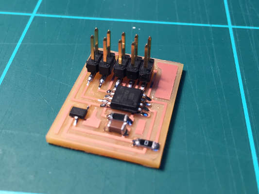 To tight design, can not fit the connectors .
I solved this with a 2 x 5 connector which just fitted. But now since I did not have an FTDI to power my board I also needed to add a bridge to my ISP programmer so it could supply power to power the board.
Programming went fine at least no errors but now I need to figure out how to power it while running it and how it would connect to my computer!?. Lost and confused I talked with Francisco and he showed me that I need to make a second board (from the networking week.) to make this all work. This got a bit to much, felt like I was trying to run before I even could crawl. So to keep things simple for the first board and to get the whole workflow I decided to go back to Neils hall board, mill and stuff it and start looking at programming from there.
While stuffing it Francisco suggested I add an LED to get some feed back if the board i working. Having already milled it, we found a dirty hack to get a LED in there. We connected VCC to LED to resistor to PB1 Pin. This is a reversed set up from normal LED wiring. The trick is to flip the LED so the cathode faced the pin. Since the LED is connected to VCC it will be off when pin is High (1) and on when pin is low (0).
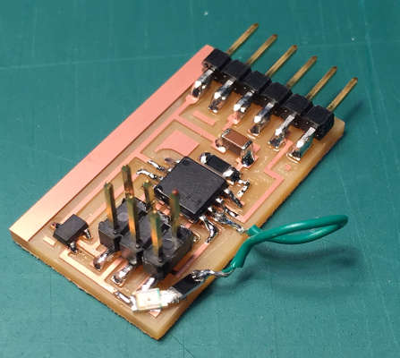 Ghetto bridging, added an LED after the board was milled.
Programming the fabISP and a make file went fine and to see if it all works I used the Python program supplied from the class web page. Running a Python program in Ubuntu was new for me so here is a mental note to my self:
python hello.mag.45.py /dev/ttyUSB0 ls /dev/tty* in terminal to list of all USB portsHall Sensor from Anders Haldin on Vimeo.
Digging in to C programming and registers of ATtiny45 I was able to add the led light to the party. Now reacting on a voltage threshold form the Hal sensor.
Hal Sensor and LED from Anders Haldin on Vimeo.
Deeper down the rabbit hole.
Following the spiral development I wanted to make it smarter by adding an interrupt. I did not have the time to do it in week 7 so this was a good opportunity. I started out modifying Neils code but got nowhere. So I simplified, went back to my hello board with a button and LED and started over. First I followed Elliot Williams tutorial from his AVR Programming book. But he used a different micro controllers so the register names did not match up. Then I combined tutorials from Internet and documentation from Fab Academy and got 98% of the way. Francisco's debugging helped me get the last 2% and tremendous relief to see it finally working.
The mistake I had made was that since I was using a pin change interrupt on PA7 I also assumed that the vector name should be (PCINT7_vect). as it it written in the data sheet. As it turned out the AVR designers decided to label the pin-change interrupts by number instead of the letter-number pairs that they labeled the pins with.
Here is a page that helped us sort that out AVR Lib Reference Manual
Modules
You can find the code for the Interrupt Button in week 7 in my documentation.
So with that sorted, back to pin interrupt with the HALL sensor.
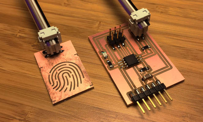
Step Sensor
Energized with previous success I threw my self at a Step sensor. This time Eagle was the tool of choice as I wanted to refresh my memory of eagle work flow. After endless clicking and dragging nodes around I came out with a working solution. I have been a clicking monkey all my life but I really start to appreciate the beauty and cleverness of code and Kokopelli. Milling and stuffing was enjoyable and without exciting stories to tell.
However when i tried to upload some code I got the following error:
Expected signature for ATtiny45 is 1E 9206

Talking with Francisco he said that rc= -1 error must be from the 6 pins to the micro controller or that the ATtiny 45 is just broken from the start, something he have experienced a lot.
Internet says the same: Sounds like one or more of the six connections to the ATtiny are misplaced or broken.
I started going through my board with a multi meter and soon discovered that Miso and Mosi was connected somewhere! Removing the ATtiny 45 I saw that I had placed the traces to close to the pad and forgot to do a design check before exporting the PNG.
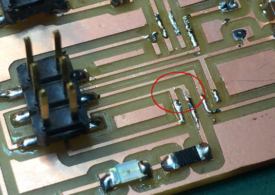 Voltage meter is my new best friend!
So the code got uploaded but there where no response when touching the pad!? All meters stabilize at 511.5 when plugging in the touch plate... maybe a calibration issue my touch plate is very small compared to the one Neil used. But I soon realized that I had misunderstood the concept of step response and connected both the shield and the sense to the touch plate. no wonder it did not work.
Step sensor from Anders Haldin on Vimeo.