Switch Watch.

" Simplify and Reduce"

Project Management

Following the 12 step to project management:

  1. Find out what is key (Time, Cost,Quality)
  2. List all the tasks (Post-it notes on a wall. Don't use old once with poor sticking properties as you will fight gravity and it a fight you will most certainly loose!)
  3. Estimate time.
  4. Add up time (post it note chart) and find dependencies.
    • 18 days to deadline. Current estimation 19 days! and then I have not counted class time and coming assignments.
  5. Shorten plan.
    • Interface APPweek10_assets is a bonus. (-2 days)
    • Use the 3D printed test body/case if casting fail.
    • Replace rechargeable battery with a normal battery. (OBS! Design change and re-mill re-stuff.)
  6. Draw Gantti chart.
  7. Resources over time.
  8. Assess risks -Stay healthy.
  9. Monitoring progress.
    • Done through my weekly update my Gantti chart in GanttProject and Trello for task management.
  10. (Monitoring cost)
  11. Reschedule (Half way through project, 3:de of June)
  12. Follow up (Every Sunday night)


Writing out all the tasks and finding dependencies.

Tuesday 26:th of May.

Programming

I started programming with my Binary watch with board I did in output week. I defining functions for each LED so I can easily call them when I got the time code figured out. It went well until I started combining function calls (turning on LED:s for seconds min hours). Turning on one LED at a time was no problem but certain combinations of LED used the same pins and it turned on different LED from what where in the functions.

After flipping pins like a mad man and documenting what goes where I have come to the conclusion that it might not be possible to this project with Charlieplexing! To display time I need pretty much all possible combinations so I would end up one time or another having e.g. PA1 and PA2 high and low at the same time, that can only happen in Schrodingers box... or I could PWM between them... but that is a whole other beast to tackle. I am now concidering the Atmel 328p. It got 23 programmable pins so it would cover my needs, but there wil be a lot of wires and a bit sad that it is not a intelligent solution.


PCB Design

Started wiring the 328 in Kokopelli. There are so many wires that the size of the watch is getting redicoulus big. I'm also having problems fitting the ISP head. Considering to make a double sided board or have the ISP separate and use jumper wires... but I'm concerned it is going to be unstable and a pain to work with.

Work in progress, Kokopelli design with Atmega328p.

Wednesday 27:th of May.

Programming Time

Former Fab Academy student Andrew Leek came by the lab today and showed me the dark secrets of Charlieplexing. Instead of turning one pin on and another pin off for lighting different LED, he showed me how to turn all pins on & off over time, but really fast! This way you have full control over all the LEDs, it all starts with an nested array. The draw back of doing it this way is that as they are turned on and off the brightness get reduce a little bit depending in how fast the processor is running.

For the time counting we went on looking at the timing and time prescaling. We gutted some Arduino library to get the "millis" "function and a ways to self adjust for the overflow of ticks. Unfortunately we ran in to some conflicts that seems to be related to Arduino library land, it was a long list but among other surprising errors where: undefined reference to `sei'
(Later I figured out what the problem was embarrassingly to admit it but I had forgot the #include avr/interrupt.h )

The good news form todays insights is that I now can go back to use the ATtiny 44. I prefer it over the 328 both from a size and price point of view.

I made the time counting code work with interrupts, so for every clock cycle it would interrupt and I would increment a variable when that reaches up to one sec (amount of ticks depends on the prescaler) I add one to the seconds variable, when seconds reach 60 I set it back to 0 and add one to the minute variable and so on it cascades downward.

So time counting is all fine and well but now I have to translate theses variables to LED lighting up in binary. First I thought of just making it with if statements, but that would end up with a LOT of if statements. Then I was recommended to do bit shifting. Here Andrew once again was a great help guiding me through the whole process.

Searching within documents with terminal command.

If you don't want to install additional software, you can simply use grep in the terminal. To recursively search through directories, you can use the -r option (see man grep for details). The syntax you are looking for is

grep -r "[STRING TO SEARCH FOR]" "[DIRECTORY TO SEARCH]"

So, for instance if I want to search for the string "asdf" in all files in all subdirectories of "/tmp/testdir/" the command looks like this:

grep -r "asdf" "/tmp/testdir/"

The quotation marks are not strictly necessary, but if your string or directory path contains whitespace, you otherwise would have to mask them using the \ character...

Thursday 28:th of May.

Translating time..

Translate time to binary. I have an array list with the LED states and I got a timer running cascading down to hours, minutes, seconds now I needed connect these two. Here i have to give Kudos to Andrew Leek who have been a champ at helping me.
One interesting realization was that I can not translate e.g. 36 seconds straight to binary as that is different from 3 & 6 what I needed to do is to separate them in to columns of 3 and 6 and then do a bitwise operator get the right binary

Debugging

I got the LED:s to light up with the pre-set time, but it would not move forward. Started debugging by pasting the function call turnOn(1); to just turn on the first sec. to see where in my code it get stuck. I found out that if I put it in my interrupt and in my if statement for if (ticks >= OVERFLOWS_PER_SECOND) it would not lit up, so something where wrong either with the counting or the interrupt not being called. I manually set the ticks to the overflow number and had the turnOn(1); inside of the if statement... that worked so something with my interrupt was not working. After some research I found a Arduino forum discussing the ATtiny and interrupt from that I could read that there is also a "TIM0_OVF_vect" hmm... why not try that one... And it worked!!!

I was calling it "TIMER0_OVF_vect" instead of "TIM0_OVF_vect"

charlie time from Anders Haldin on Vimeo.

Time Code:


Bitwise operator

First I needed to split seconds apart so 25 seconds would become 2 and 5. I did that with the % and / operator. I sorted my nested array list from seconds to hours so now I could use bitwise operators to go the next one in the list.

Friday 29:th of May.

3D Scanning.

In hope of getting a comfortable fit I 3D scanned my wrist with Skinnect. I choose objects and 30x30x30 box for my settings. I just needed a small part of my wrist so the scan was pretty easy. But here are some top tips for improving the scans.

  • Try to scan one area only once.
  • God lighting really makes a difference.
  • Fix your posture, scanned object should be as still as possible
  • For fingers and hands put marking tape and draw lines dots on it. (Fingers are really hard to capture, we got the best result when the hand was on a surface prohibiting all movement and with a smaller scan area to get more resolution.)

  • 3D scanning with Skinnect.

    Saturday 30:th of May.

    Case design..

    I had a hard time deciding what cad software to use for modeling the case. I really like Antimony but I'm concerned that it is still in heavy development and if there is a software update that break backward comparability I might end up in a world of pain.

    The other option is Free cad, I quite enjoyed working with it week 2, But I'm still very new to it so not sure I can pull it off. Inspired by Theodore Roosevelt quote "In any moment of decision, the best thing you can do is the right thing, the next best thing is the wrong thing and the worst thing you can do is nothing."" I started out with Freecad.

    Freecad enclosure v1.

    I really wanted to make a round watch but having measured the components and giving some extra space I came to the conclusion that it was going to be "humongous"! So a square design for the first prototype it is then. I based the size on a generous component spacing. Made a simple model and 3D printed it to get a feel for the size... it was big... way to big. I really need to squeezes the components. To know how small I can go I really need to finish the PCB layout first.

    Having solved the Charlieplexing problem I could now have the much smaller ATtiny 44 which meant the case can be much smaller. Continuing in Freecad I modeled the case in the part design workbench. I quite like it being parametric and all, although I experienced some problems with it breaking when referencing lines on external geometry and then changing the over all size of the part.

    With the case modeled I took i the outline shape and did a boolean operator on the 3D printed Wrist in Blender. Then I imported the case and union the two shapes together. I had to make some small adjustment to get the strap attachment nicely merged with the bottom shape and then send it of to the 3D printer for a test print.

    Subtracting the shape of the 3D scanned wrist from my case design.

    Sunday 31:st of May.

    Board design.

    Iterating on my board design from output week i removed the capacitor and resistor going to VCC/reset since they are not needed as DC voltage opposite to AC is stable. I added two pads/button for time setting and...Batteries on the back side.

    Kokopelli final layout.
    Back side, traces for the battery holders.

    Monday 1:st of June.

    Milling stuffing v1.2.

    Today I milled and stuffed my second prototype board. The board milled beautifully but there where something wrong with the scaling!


    Not discourage by the setback I continued to stuff the board. Found a good technique for soldering LED:s Since the LED:s absorbs energy much faster then the pad on the PCB. by first heating only the pad for 5 sec and then touch both the pad and the led for 3 sec I could get a nice flow of solder between the pad and the LED... Top top of the day!

    Before programming I weirdly sensed something where wrong, so I started probing with the multimeter in continuity mode. To my surplice I found that VCC and ground where connected! I noticed that it did not matter what position the switch had it would always short circuit. So I removed the switch and look under the microscope...


    Having removed the excess copper material I uploaded the time code and I was very happy to see it worked beautifully.

    I started looking at the code for step response... first from Neils code. I made some adjustments because he is using ATtiny 45 and I ATtiny 44. trying things back and forth I got it to work... or so I thought. Coming back from celebration cake (important to celebrate small successes) it no longer worked. and I did not get it to work for the rest of the day. Time to get some help.

    Design changes.

    I have noticed that my design does not go easy on the batteries, to get longer battery life and to scope the project I decide to change my step response button from time setting to display time. That means that the watch would always be running but only light up the LED:s when the step response button is touched.

    Having my board powered with batteries I made a slight modification to my Fab ISP:


    Now I can choose if I want to power my board or not through the Fab ISP.

    Tuesday 2:nd of June.

    Milling stuffing v1.2.

    Continued with step response programming, found that I was doing a ADC on a pin that did not have ADC so I added some jumper wires. I use Neils code to get and idea what range I'm in but cant get it to work. I added a RX and ground solder jumper to my board to get the signal to the FTDI but with no luck. No data seamed to be transfered and the serial pin is set to stable 5V not sure whats wrong? (2 days later I found out that on of my lines in my FTDI cable was broken)

    My board getting butchered while debugging. I named it Quasimodo.

    Will continue on to PCB design while waiting for help. I'm doing a double sided board with the batteries on the back side so I removed the switch and made two holes instead. At first I tried to just draw lines for the battery holder pads but it got very messy so then I made a custom class for it, pulling the measurement form the data sheet, much better solution and now reusable. I can just fit in two battery holders next to each other.

    Wednesday 3:de of June.

    Case design.

    Went back to free cad and put in my new measurement. All the referenced points on a external mesh then broke! So I ended up redrawing it again. Exported the new model in to Blender and did a boolean operation from my wrist scan (mesh). It looked blocky and heavy so I started adding small edges features to the outer shell. Pleased with the improved design I went on to mold making.


    Here I realized the constraints you have to think of when designing for molding and casting. Think it have to be a 4 part mold if I want it to be make this current design... or simplify it for two part mold.

    Mental note: Design a crappy version as fast as possible to go all the way to see all the traps.

    I decided to simplify the design so it would work in a two part mold. It was a quick fix and of th the 3D printer for a test. The result I got was very furry, The reason for this was I thought I printed with TX material and had the settings for ABS with increased flow to 112% But I had used PLA. After bit of cleaning and sanding it was actually very comfortable to wear,bulky but comfortable. 34mm x 44 mm should be 35 x 46 that is quiet the shrinkage.

    3D printed third iteration of case
    Project taking shape.

    Back to step response button.

    My board is now so hacked that even Quasimodo would look like a Prince compared to it. I re-flashed the time code to make sure it was still working, it wasT The only difference I could see in Neils design and mine is that he has a shield that pass the resistor and continue out in to the cable, but not getting connected to the touch plate. I'm not sure if they are needed but I change my board so that button one is the shield and button two is the sense plate. And now it worked! Not really understanding why I experimented to cut the shield plate small, first 1/2 then 1/4 but it did not make any noticeable different. What made a different though was when I unplugged it an went on battery power! Now it would not work!
    Reason: Powered with the computer I get 3.7V coming out the pin with 6V battery I got 1.7V I Measured my batteries They where down to 2.6V! This is going to be a problem! ...and why is my batteries running out so fast? Sometimes I forget to turn the switch off when I plug it in the computer is this killing the batteries? (Yes!)


    Project management update.

    Today was also reschedule day. Reality check on what task are left and do I need to cut features to make it in time. I have all my tasks split out and estimated in Trello.com and the Gantti chart I use for the bigger overview. I re arrange my tasks a bit but it look like I'm on track... as long as things don't starts to go wrong.

    Thursday 4:th of June.

    Mill(er) Time.

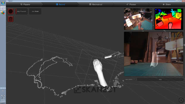
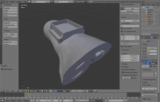
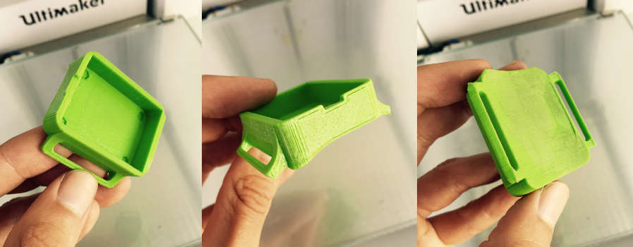
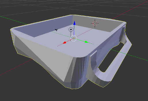
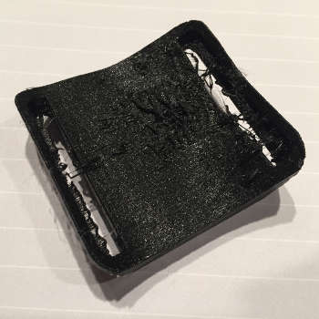
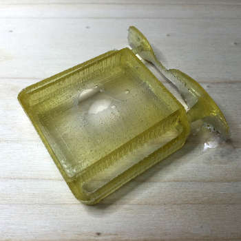
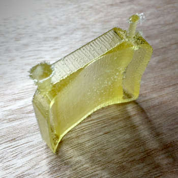
    My 3D printed part had a hole in it where it was the thinnest. It was probably to thin to print. and will definitely case problems in the molding process. So I went back to my 3D model and increased the distance to... and re did the mold in Blender

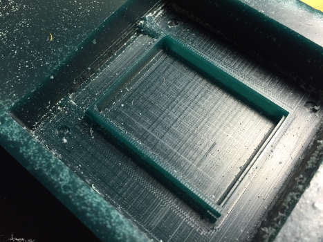
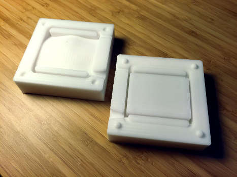
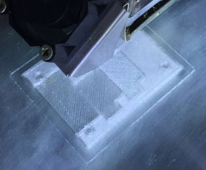
    I milled the top half on the Roland modella first with a 1/8 bit and final pas with a 1/32 bit end mill. On the first pass, of the final cut, the drill bit really dug in to the side. Remember tilted walls! I compensated for this with the clearance setting. After a couple of tries I got a nice working setting clearance diameter 3.35mm, clearance length 2.

    Roland MDX 20 clearance settings from Anders Haldin on Vimeo.

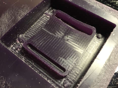
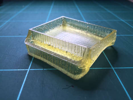
    For the bottom half I got curious if I would do the final pass with the 1/8 bit as well... I had no small details in the design that required a smaller end mill. Dangerous to start experimenting when you are on a tight schedule... but I'm here to learn so I went for it. I used the default settings in (local) Fab modules I only change the overlap to 65%... and it turned out very well.

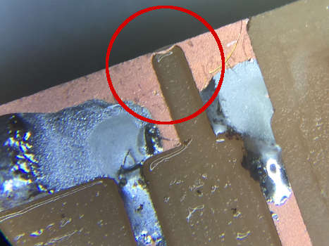
    Inspecting my finish molds I noticed that the first one had not milled properly. It was missing about 1 mm in depth. I assume something got pushed when the end mill got stuck in wax. I will redo that one tomorrow.

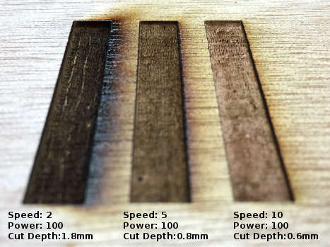
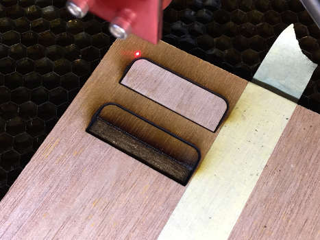
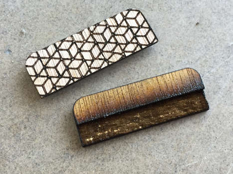
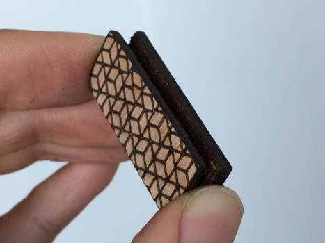
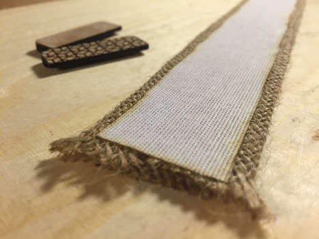
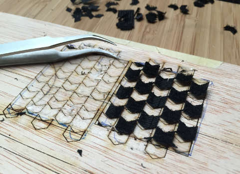
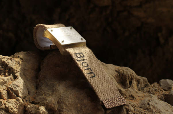
    While my mold was milling I looked at some burlap and thought maybe I should use this for the strap? Plastic leather and old wood just seems like an weird material combination but burlap and old wood fits much better, get more of a worn beach look. And could I raster burlap with the laser... just burn it a little bit?

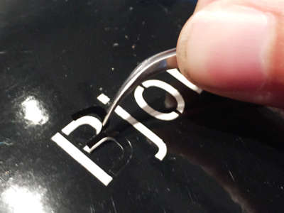
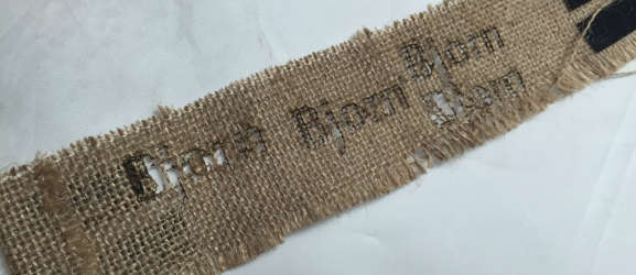
    Not such a good idea maybe vinyl cut and spray paint is a better option...

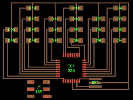
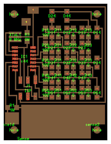
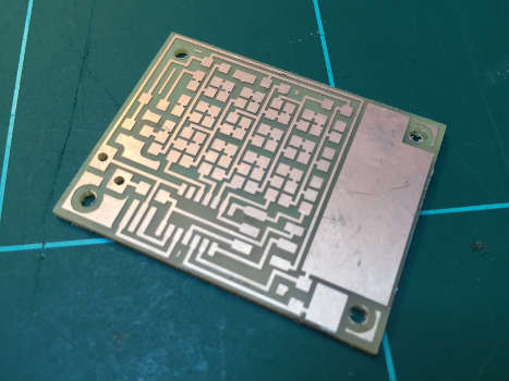
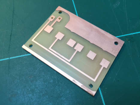
    Milling double layered PBC

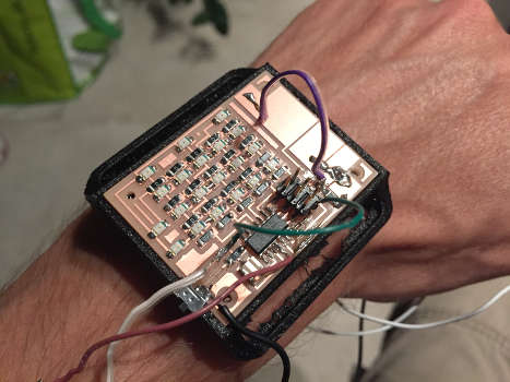
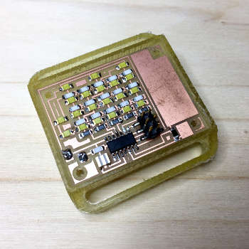
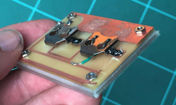
    I moved on to mill the PBC, I'm making a double sided board, having batteries on the back side, I had made both side in Kokopelli retro and just commented/uncommented the part I wanted to export. The working order for milling a two sided PCB is:

    • Run the trace job
    • Run the cut holes job
    • Run the cut out board job
    • Remove it and clean up the back side.
    • Add double sided tape to the milled side.
    • Place it back using the cut out frame ass a reference.(make adjustments before pressing it down)

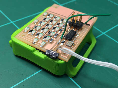
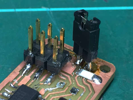
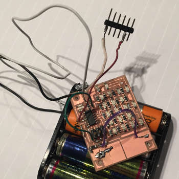
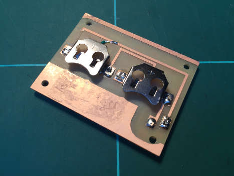
    The board came out nicely but I had unfortunately made an design error, plugged the returning battery cable from + not - as it should be... so we are back to jumper wires.
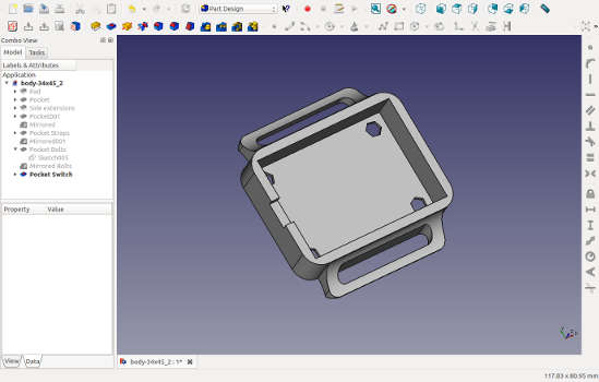

    Designing Top part

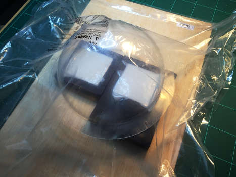
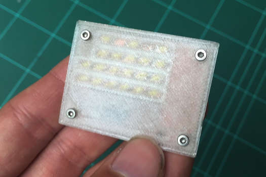
    I modeled the top part in free cad. I used boolean operator to get different depths (0.3mm, 0.5mm and 0.8 mm) for a thickness test. I'm experimenting with transparent filament but I'm quite sure I want it in wood in the end. I started to do a test print to see if my measurement was correct.

    The transparent material I'm using is transparent XT-COPOLYESTERdepending on the temperature you print at you get different translucence.Printing at 240 degrees gives more translucence then 270 degrees.

    Print settings:

  • Speed 65% (of 150)
  • nozzle temperature 240
  • bed temperature 90
  • material flow 118%
  • I was recommended to use masking tape for better adhesion and to avoid wrapping. But I could not get it to stick so I went back to the trusted glue stick. Even here I had problems but when I slowed down the speed to 65% it worked like a charm.

    Transparent test print.
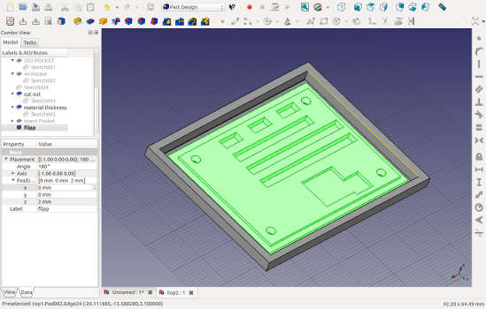
    Top designed in Freecad.
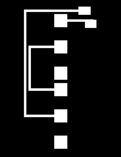
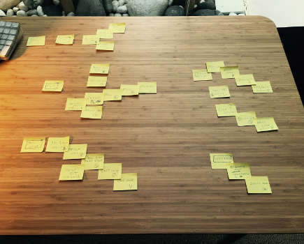
    Friday 5:th of June.

    Re Milling.

    This morning I re milled the top mold. Having great success with milling the final pass with the 1/8 end mill I tried it although I suspected it be to big for milling out the negative aliment spheres, my suspicion where right. I swapped to a 1/16th end mill clearance length: 3.5mm clearance diameter 3.3mm. It worked very well.

    Stuffing the PCB.

    While that was milling I started stuffing my broad. For the vias I double folded a copper wire and soldered it from both sides. I don't solder the ISP head because it to high for my design but will place it manually when I upload the code

    I put my batteries switch in my fab ISP to not supply power and uploaded code the dreaded rc -1 error. checked it under the microscope found some micro wires that I cleaned up but still would not work... Well that is tomorrows problem... onward to casting.

    Casting.

    To convert my volume of the two molds to gram I filled them with water and weight the total amount. I know that Forme X density is 1.1g/cm3 and I added 1.2 for material getting stuck int the cup. My calculation looked like the following:

    175g x 1.1 x 1.2 = 231 (rounded it to 235)

  • Part A: 235g
  • Part B: 4.7g
  • Total: 239.7g rounded to 240g
  • Stirred it carefully trying to avoid adding bubbles and pored it in to the molds. For vacuum we got an IKEA vacuum bag and a vacuum cleaner unfortunately after about 5 min the vacuum cleaner overheated and the bag lost it vacuum soon after that, the bag must have a puncture somewhere. Not much to do about that just hope that it at least sucked the away form the casting surface.

    Punctured vacuum bag.
    Final molds.

    Late evening I came back to debunk my RC-1 error. I really did not change much from my version 2,"Quasimodo", to v3, "Pongo". I inspected it under the microscope. Found some suspect micro wires that I cleaned but the rest looked good. Francisco suspected that there where not good electrical contact from the ISP header to the board. I soldered it and now I could upload code!

    time pongoboard from Anders Haldin on Vimeo.

    Saturday 6:th of June.

    Milling the top part in wood.

    What I learned from the test mill:

  • Set overlap to 0.5 was 0.25.
  • Don't put double sided tape under the part you want to use.
  • It have to be thinner for the LED to shine through.
  • No need to pocket each led can do a whole row.
  • Height calibration is REALY important when you dealing with 0.2 mm distances.

  • My test material is 3mm thick and I want my part to be 2mm and cut out... or in other words I wanted to remove 1 mm of material before start milling my piece. I experimented a bit with the top z and bot z setting them to -1 and -3.2 but this would not remove the extra mm of material but just start cutting my pockets at the set depth, -1 in this case. I solved it by adding a frame around my part that where the height of the material. Now it milled my piece to the tight thickness. (As off writing this I realized I could have run two jobs one just to get the right material thickness and another to mill the actual part!?)


    Casting the enclosure.

    The mold came out really nice, no bubbles on the surface and a perfect fit very happy about that. I'm casting the case with Smooth-on PMC-780 DRY. I got it for my long board wheels but I think it will work nicely for the enclosure as well. Mixing was easy with 2:1 ratio.

    The 780 is transparent with a yellow tint, I called it dehydrated urine 5 but Maria positively framed it as honey color.

    Being transparent it had the other benefit that you can see what stirring movement generates bubbles. I used a syringe to inject it into the the mold. It took not long before the the 780 started pouring out of the air vents, first with a lot of bubbles so I continued injecting until only a clean liquid came out. A quick clean up of the mold and in to the newly bought vacuum bag.

    New vacuum bag with happy colors.

    Sunday 7:th of June.

    Wrist strap.

    I measure the circumference of my wrist. Laser cut Burlap with settings: Speed 80, Power 45 and Linen Speed:80 Power 30

    For the end of the wrist strap I wanted two pieces of wood clamping the cloth together. I contemplated if I should mill it or try laser cut it. Since there where very little laser cutting on this project I decided to go with the laser. Also experiment to see how deep I can engrave in to the material.

    First off was to find the settings. I did a structured test for all three jobs, deep engraving (I call it carve in my notes), cutting 4mm plywood and vector engraving with 3mm offset in order to get thicker lines (Since the job was so small there where not really any time savings doing it this way I could just have used rasters)

    Laser engraving test.
    Using the cut out frame as a reference for engraving the back side.

    I'm doing a double sided job and I I had separate files for the two sides they obviously needed to match up but the Full spectrum Retinaengrave 3D software has a "smart" feature called auto crop, where it crops the design to the boundaries when importing and this would offset my two sides. To fix this and have my 3 files matching (carve, engrave and cut out) I had to add the the top cut line to the carve file and set the BW threshold down to 250. Now it cropped all the files to the same size.

    The workflow for getting the two end strap pieces was as follows:

    • Raster the pocket withe settings: Speed: 2 Power: 100.
    • Cut out the piece, setting: Speed: 20 Power 100.
    • Flip the one the are getting engraved using the cut out frame as reference.
    • Offset laser 3mm in height vector cut (engrave) with setting Speed: 100 Power:1


    Vinyl cut mask.

    I thought of pimping the strap wit some design. Not being able to lase engrave on burlap I went for vinyl cutting a mask and spray painting. Settings for Vinyl cutter: Force 45g, Velocity: 5 (cm/2) pen force +2 Cut beautifully.

    Would have been smart to add some guide lines when I'm going to apply it to the strap.


    Weeding vinyl is like Zen gardens for graphic nerds.

    Monday 8:th of June.

    Assembly.

    De-molding the enclosure reviled a half fail. First the material was much softer then I had expected. The sample I felt in the shop when choosing material was a solid block and this is a very thin structure. So not the best choose of material but still acceptable. What was worse was that there where a hole in the thinnest part of the model. (same as when I 3D printed) My thickness adjustments where obviously not enough. I knew I was pushing it, being greedy with the thickness of the bottom, and what also affected the outcome was that I probably squeezed it to hard with the clamps in the center so the two mold faces where touching. On the good side though the measurement was correct and it all fits.


    Merging code.

    I want to have the LED switched off by default and only when I touch the button it will display time for 5 sec. I have my time code and a modified version of Neils step response load code both working separately. As I started merging them I quickly realized that this was not so easy as I thought. As the LEDs are dependent on the while loop for switching pins on and off and preferable going as fast as possible. The step response code have delays in it, this causes two problems. One the LED get very dim and two this will interfere with the time counting as the delays are locking the whole AVR.

    After half a day of testing back and forth, sticking my head in many different rabbit holes I accidentally came up with a inverted solution, meaning I could turn my LED off when pressing the button. what I did was: if (down_hi == 1) call my turn off all LED delay for 2 sec and finally add 2 seconds to seconds variable. I actually don't understand why it works?!

    So now to invert it I will try looping the updateDisplay(); for 5 sec. And it still dims my LED to a faint glow thanks to the delays in the step response code. It is a nasty hack but that is how the cookie crumble T-1 to deadline.

    Strap.

    I used Fliselina and a hot iron to glue the folded strap ...and that's all I have to say about that.


    Tuesday 9:th of June.

    Assembly continued.

    Comparing the two top covers, the milled wood and a 3D printed test, I decided to go with he 3D printed as it is more transparent and a better match with the casted enclosure. I started a print with the correct measurement and with transparent filament. I also re-made the Velcro taking advantage of the laser cutter re using the pattern form the engraving a quick paint job with the vinyl cut mask and spray paint and finally I laser cut a wooden piece for the other end to keep the burlap from disintegrating.


    Calibrating step response.

    This was a bit tricky first it reacts differently through different material, second is that a setting that works while the programmer is giving power do not work when I switched to battery power! after much cable switching I got a setting that worked.


    Optimizing code.

    I wanted to fix the faint LED problem by removing the delays int the step response part of the code. My solution to this was to track the delay time in the loop. Instead of using the settle_delay and charge_delay I set some boolean flags to track the current state or part of the charge/settle I'm are currently in.

    But that was not enough, even the while (ADCSRA & (1 << ADSC)) affected the brightness of the LED:s. I started ripping out all code out that where not essential. No second measurement on step down for noise reduction and no sample and hold... With the bare minimum I got to an acceptable brightness level but at a price of the step response button not working through my top cover material.

    Optimizing Code:


    Wednesday 10:th of June, T-0

    Second take at casting the enclosure.

    Being short of time I used a scalpel to modify the mold, cutting of the highest peak. I also used duct tape instead of a clamp for fixing the to parts together. Got a very nice result, enclosure is thin but not to thin.


    Putting it all this to together this is the result:


    Post presentation work.

    Tying loose ends.

    I debugged my Quasimodo board with the oscilloscope and found at that my PB3 pin was completely dead. Moving my serial communication to PA0 and I got communication. Now I could read my values from the step response through the Python script Neil has in input week. With the numbers I can now write some proper code that actually makes sense.

    I experimented with swapping the 1M to a 5M ohm resistor to see if that would make it easier to measure capacitance through my cover. But the numbers I got through the Python program showed very small difference from touch and no touch... I probably also should have played around with the delay times to get a better result.


    Conclusion.

    What I have learner, re-learned

  • Self motivation is key.
  • Keep moving forward, don't allow your self to get stuck.
  • Dream big but start with MVP.(Minimum Viable Product)
  • Fail fast and then iterate. Better to just get going, progress inspires while to much thinking can sometimes bog you down and drain you.
  • The more you do a process the faster and more comfortable you get with it and they wont seem so big in your head.
  • A expert is truly the one who have made all the mistakes and learned from them.
  • Use tilted walls in my mold.
  • Do structured documentation, helps you debug code and settings for e.g laser cutter.


  • Download Assets:

  • Assets files for Final Project.

  • Google+

    Follow me on Google +.

    Click me

    Twitter

    Twitter madness.

    Click me

    LinkedIn

    Connect with me on LinkedIn.

    Click me