WARNING there is no diode controller input! if you plug the PSU upside down, it burns!


I combine holes and cut to do the mill in the same operation
Work this week at the fabacademy is to build an actuator circuit and the control with microcontrollers.
I wish to make a / flashing headlights Central for my velomobile.
To operate a little more the possibilities of tiny (because otherwise I could have fair all without microcontroller),
I'll create features like code / headlights
(PWM) and signal / warnings.
Because it's a mosfet board, it's also a multipurpose device for
activating motors or solenoids.
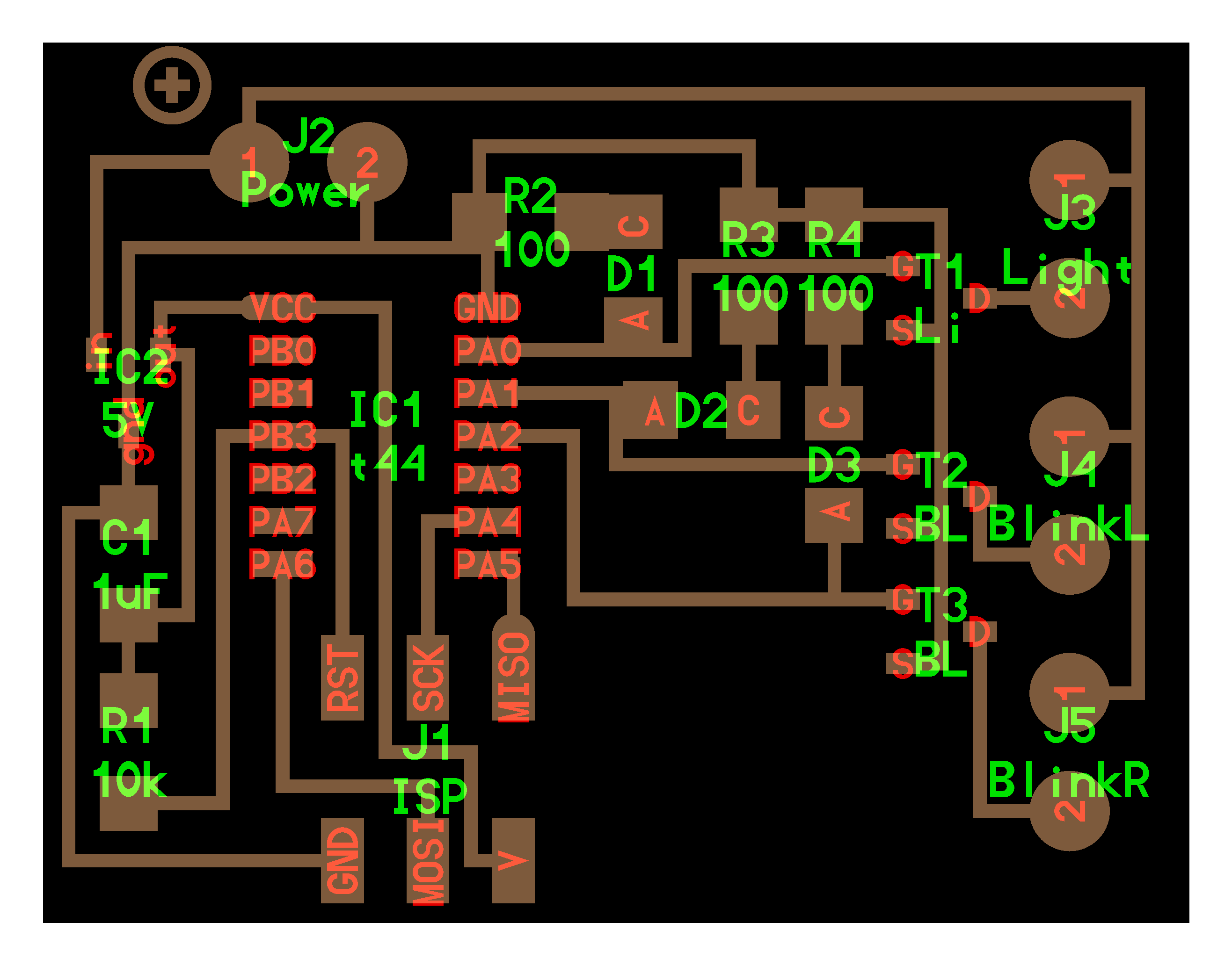
I use FabModules to draw the circuit: make_cad_png
This is a ATTINY44 piloted by three switches, for operating 3 mosfets.
The card is provided with a voltage regulator, and the lights may be powered at different voltages.
According to the datasheet of mosfet (N), and the regulator may supply the circuit until 30V
I add leds to the outputs to get adicators for activations of mosfets

WARNING there is no diode controller input!
if you plug the PSU upside down, it burns!


I combine holes and cut to do the mill in the same operation
| id |
component | amount |
|---|---|---|
| D1, D2, D3 | Red leds 1206 smd | 3 |
| R1 | Resistance 1206 cms 10KB | 1 |
| R2, R3, R4 | 1206 cms Resistance 100 Ohms | 3 |
| C1 | 1206 cms capacitor 1uF | 1 |
| IC1 | ATtiny44SSU | 1 |
| IC2 | regulator 5V/100mA LM3480IM3-5.0 | 1 |
| T1, T2, T3 | Mosfets N 30V 1.7A | 3 |
| J1 | 6-pin ISP connector | 1 |
| J2, J3, J4, J5 | screw terminals not 3.5mm | 4 |
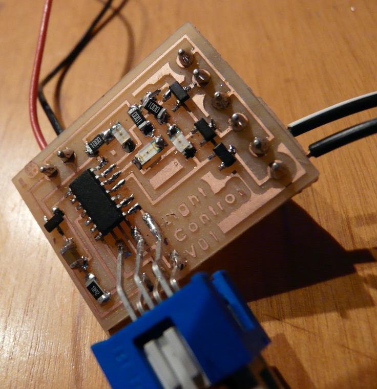
during milling, I was unsure of the
horizontality of the work plan, I settled in fabmodules a slightly
larger than normal depth: 0.12mm instead of 0.1
We see the difference because the inter-tracks are much more
hollow, then tracks and fine patterns are more fragile:
this is particularly evident for the text, but it will be careful when
soldering, because the fine tracks can be tendency to come off.

Although I'm getting better every time, I think
I still have some progress soldering technique ;)
Screw terminals, through, are soldered to the back of the circuit.
I used the small code below to test the circuit: I had me try several times to correct any small errors in welding.
I'm coding in C, starting from examples of
the course
To validate the circuit
I made a simple code that flashes the outputs
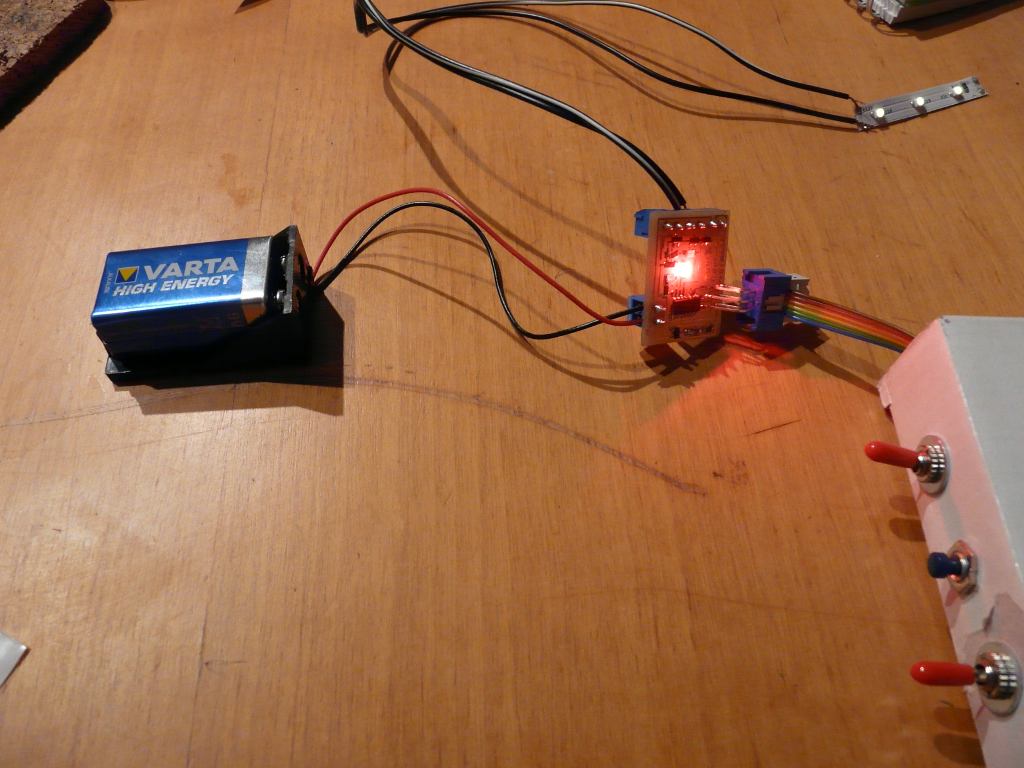
I stourted with a switching power supply recovery, but the microcontroller does not respond well. It seems that the power dropped much voltage under load, yet not so huge ...
Finally, I put a 9V battery and it works well.
3 switches are wired to the ISP connector inputs PA4, PA5 and PA6 settled pullup
1 button (PA4): each button release mode is
changed for the headlights: low> high> off
during the button pushed, it is full headlights (to the headlight flasher)
2 switchs monostable (PA5 and PA6): flashing (left and right)
if it triggers a flashing button while the headlights button is turned on, it goes into warnings.
PA0 PA1 PA2 pins are wired to the mosfets
Flashing ... flash, so it will be wise to use interrupts to detect changes even during the delay buttons blink.
some resources about the tiny interruptions:
http://www.avrfreaks.net/index.php?name=PNphpBB2&file=viewtopic&t=105493
http://www.nongnu.org/avr-libc/user-manual/group__avr__interrupts.html
in the datasheet
can be seen that all three inputs of the buttons are positioned on the
same interrupt port
I have not yet implemented the warning
function.
To put into action the interruptions, I informed the ISR function (PCINT0_vect) that is called when you stop on concerned pins .
You must write in this function tests and actions
to take when a monitored pin is changing.
Then, in the beginning of the program, I enabled the interrupt port connected to pins 0-7 or PCIE0
Then set the watch mask on pins that I whant (to not the routine triggers when the outputs are enabled)
Finally, I enabled the interrupt method:
to adjust the intensity of the lights I intend to use the PWM
Unfortunately, the outputs I used dont have pwm hardware function
Fortunately, you can make a soft pwm :
http://www.kobakant.at/DIY/?p=3393
The challenge is to make the PWM on the headlights without losing the timing of the flashing
the principle is the following:
Blink_delay corresponds to the flash duration flashing
my poorman PWM function is like that :
the final code is available here: File: Light.control.44.c.zip
As I put LED indicator on the circuit, I could encode the entire program without putting load on the mosfets.
I also mounted a small dashboard fortune to wire switches.
The behavior is completely consistent with my expectations:

I wired a small ribbon LED 12V test. It is a bit underpowered, but it will do for now.
The mosfet headlights works well
Alas, when I activate a flashing, it does not work.
Testing mosfets flashing, I see that they do not work. There must be a welding problem but I'm not lab. I should fix that later.
my circuit or otherwise disrupts the trigger mosfet, it would then set the indication LEDs downstream of mosfet (with resistors dimensioned to the supply voltage)
To be continued...