I followed the e tutorial on the project site.
Qucs seems easy enough to learn, but I guess it can quickly become very complicated to simulate complex circuits.
This week assignement is redraw the echo hello-world board,
the chip is a ATtiny44-ssu: the technical datasheet will help us to set up the circuit correctly : In the starting circuit, 4 pins are free: PB2 and PA7 (at the left), at the right PA2 and PA3 The two ports (A and B) are bi-directional with integrated pullup resistors. Port A contains 8bit pins and Port B 4 bits . This caracteristics are indiferent for us because we don't use the ADC functionnality.
I will use a Red Led. From the datasheet :
So, because the circuit will be supplied in 5V, I must add a resistor :
R = (5-2) / 0.03 = 100 Ohms
button is a switch NO (normaly open) I checked the datasheet form pads not mistaken sense because it has 4 pins. I connect it directly to the tiny because I plane to use the internal pullup resistor from controller.
As fabmodules do (almost) anything, it is possible to design PCB with the form of a descriptive language component: it is a HDL: Hardware description language. I start from the original File hello.ftdi.44.cad and I hack it by moving a few components, and adding my own:
For the processing of the PCB, I used make_cad_png
as I found it a bit austere, I added my personal touch:
thus
draw a beautyfull flower.
helloworld.cedric.cad
I try two softwares for simulate the comportemzent of components that I added
Qucs it's free electronic simulation software.
I followed the e tutorial on the project site.
Qucs seems easy enough to learn, but I guess it can quickly become very complicated to simulate complex circuits.
File:HelloWorld.led.button.sch.zip
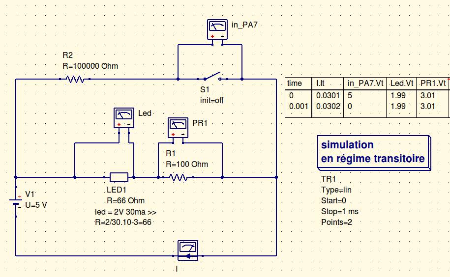
As there was no led in the library (as diodes and I could not find my settings led), I simulated one with a resistor (the time scale on which I'm studying the diagram, it makes no difference).
I then added the probes, which appear as voltmeters.
Then I placed a "transient simulation" of type linear, starting at 0 and ending at 1 ms, 2 steps to have the values in the circuit in two button states: open and closed.
In the settings of the button component, I set the "time" parameter to 1ms, which is the time it takes to change state.
Finally, I placed a table and selected values to display. Then I started the simulation.
conclusion
The result corresponds to what I expected: in the PA7 input, the pull-up resistor causes a voltage of 5V when the switch is open.
When closed, it goes to 0V.
For the LED, this simulation confirms that the selection of a resistance of 100 ohms will cause a voltage 2V across it.
CircuitLab is an online software for electrical simulation.
It is used in a web browser, and is a bit simpler than Qucs, albeit more limited too.
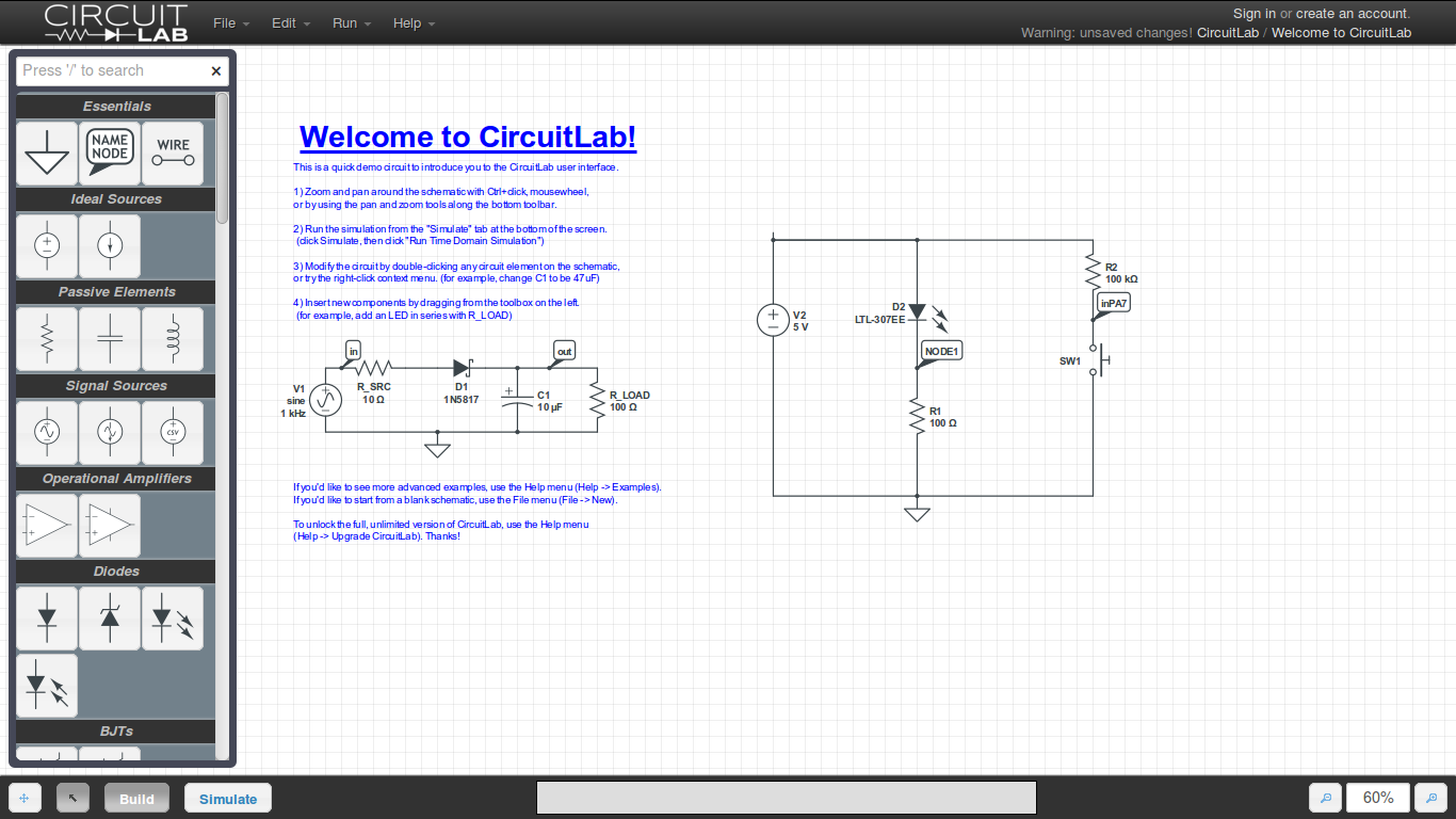
I just had time to redo the schema before being asked to register ;)
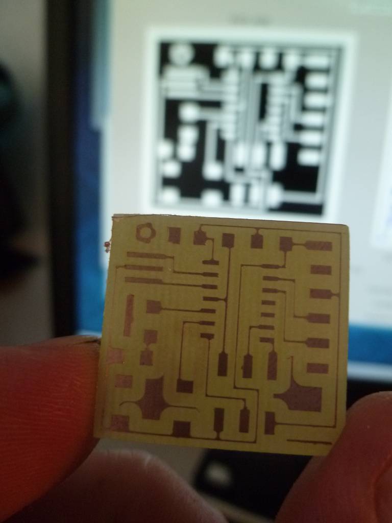
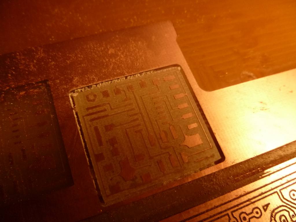
I milled the circuit with the modela and fabmodules.
As with fabISP I used a spear tip.
Against by this point is worn, it is now wider than 0.4mm, so the card was ill-defined traces: below, the missed and the guilty ...
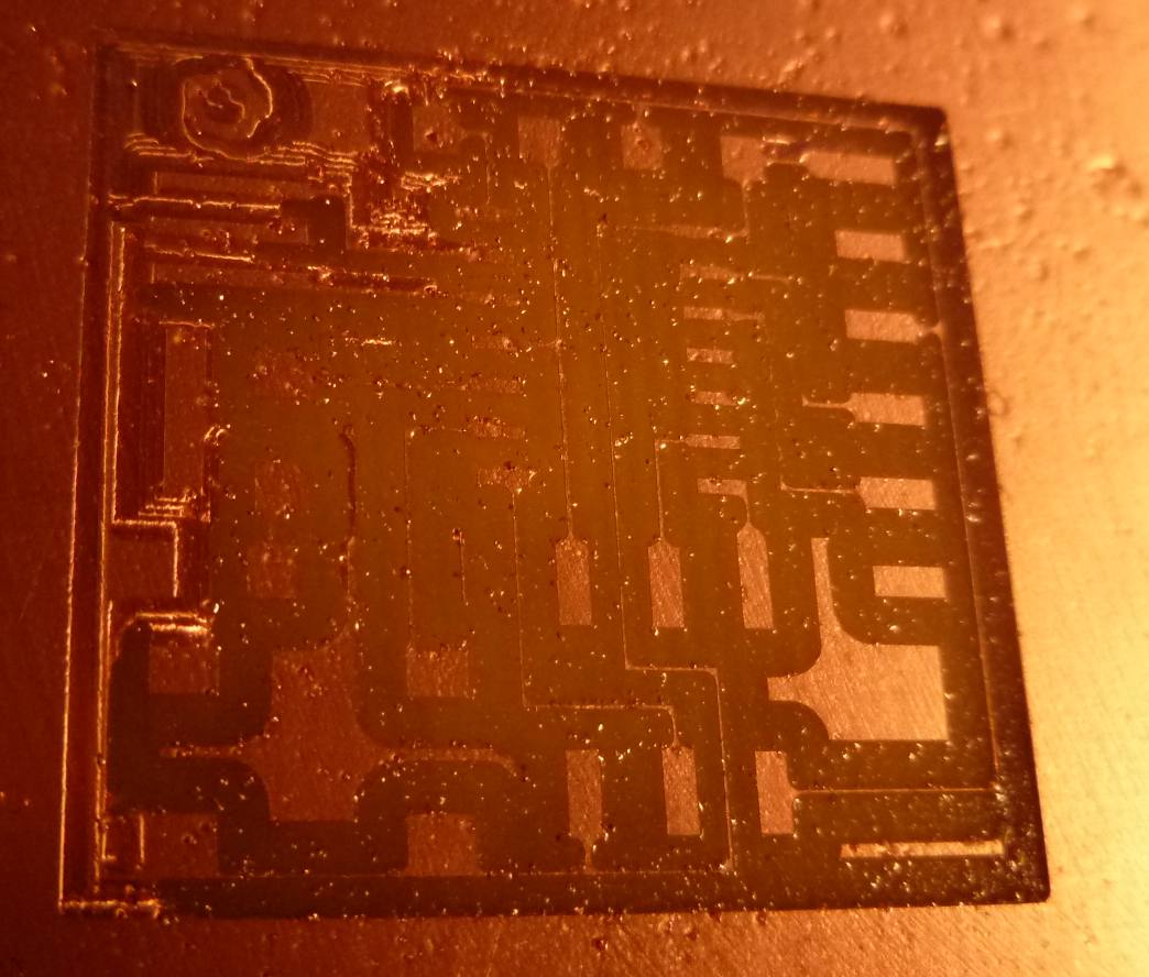
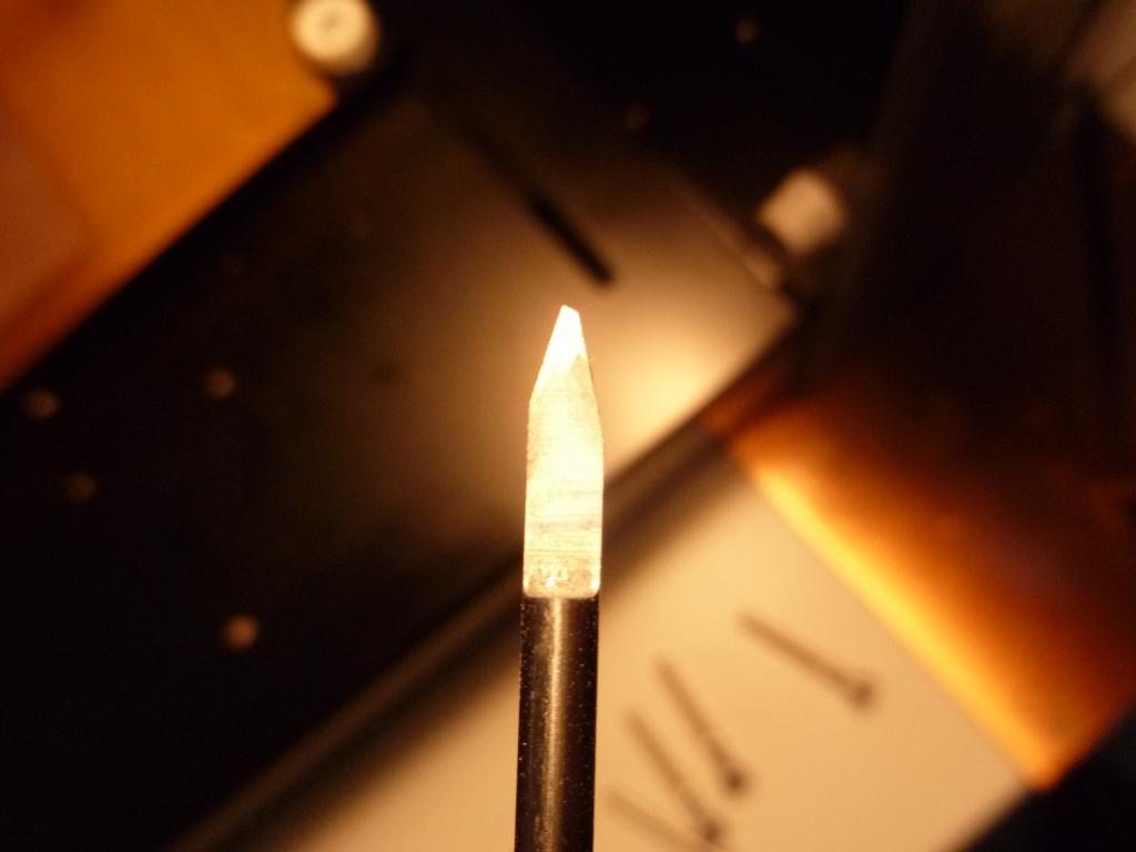
Unfortunately I have not yet received strawberries spare, so to circumvent the problem, so I set the size of the tool to 0.45mm.
This dimension is more coherent with the true size of the tip.
Fortunately it is not worn more as 0.5mm, because I saw that in fabmodules separations between tracks disappear with a tool larger than that ...
Finally, I arrived at a fairly satisfactory result:
I'm progressing slowly in soldering SMD components.
It's not so difficult: we need only a good music ...
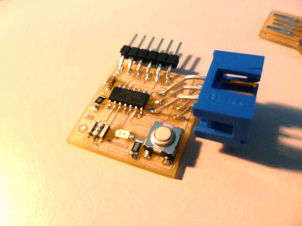
until we recieve 100 Ohm resistors, I put a 499 after the led: it will turn on a little less strongly.