Assignment: design and build a network connecting at least two processors
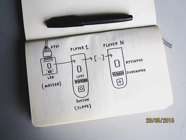
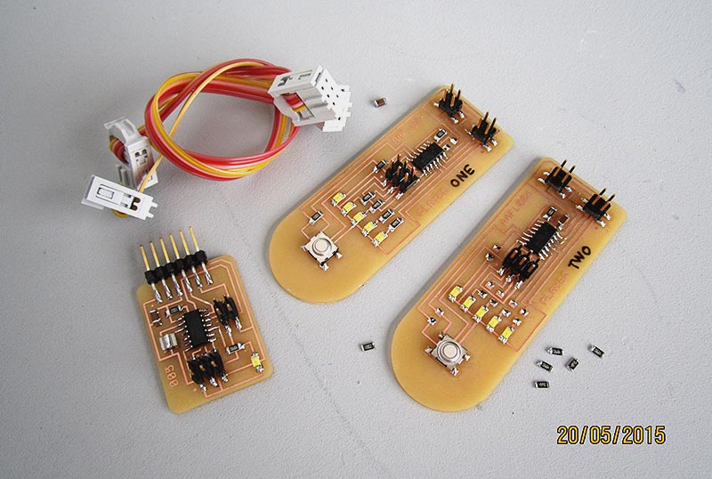
For this assignment I would like to improve the electronic game I made during the inputs and outputs weeks. The idea is to create an independent board for each player, containing the button and some leds, not only to give feedback to the player, but also to add a new feature, a scoreboard for the game. We have a master board with the main led and the FTDI connection, and as many slave boards for the players as we would like to produce, with a button and five leds.
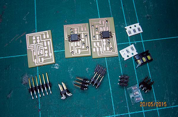
Design, mill and solder all the components. I started with the master board.
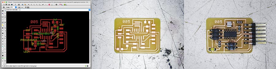
Tip for the soldering part: put first some pewter on a footprint for each component (not too much!) and then with one hand, using the twezeers, hold the component over the board and use the soldering iron to melt the pewter. Now the component is sticked on the board (but not completly covered with pewter, put more at the end!) and you can use that hand to hold the wire of pewter to solder the rest of footprints.
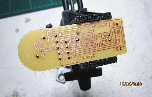
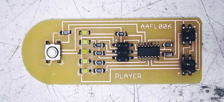
And voilà! This is the slave. I prepared two.
I start programming the master board. I get this error message doing the bootloader (the same message appear if I just wanna upload some code):
    avrdude: initialization failed, rc=-1
    Double check connections and try again, or use -F to override this check.
Ok, I check the connections and I find that the ATtiny44 is upside down. I desolder the MCU easily using a hot air gun. I solder it again with the correct orientation. Solved, this time I can put some code inside the board without any problem. I can also upload code to the first slave (I just need to change the clock, from external 20MHz to internal 8MHz), a modified version of the blink example, just to see that all the leds are working properly. So far, so good.
The serious problems start now. I try to put the same working code to the second slave board, and I get the same error message as before (initialization failed, rc=-1). In this FAQ they explain that "the response from avrdude means that it can talk to the programmer but the programmer can't talk to the chip".
This time the MCU is in its correct position. I don't see errors in the design. The soldering looks neat. I start changing connections, checking the wires, now I connect the first slave, now the second one... I don't know what I did exactly, but at some point, the first slave board, the one that worked at the beginning, stop working. A message appears on my computer a couple of times, about some problem with the power on my USB port... not a good sign.

I get stuck debugging the two slaves boards for two entire days. Jani helped me a lot during that process. Seems that there is a short circuit somewhere, but I couldn't find it. I started disassembling the boards, to simplify the circuit, in case that I can spot the problem easily, but no luck. I also burnt a led by accident. Maddening.
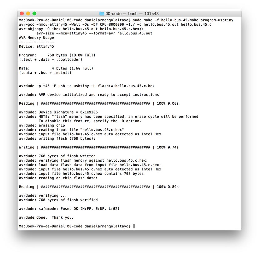
Time flies, so I decided forget about to repair the slave board and I start to mill, solder and program both Neil's asynchronous boards, bridge and node.
Connect the FTDI and the programmer to the bridge.
sudo make -f hello.bus.45.make program-usbtiny
Change hello.bus.45.c line 41 from #define node_id '0' to #define node_id '1'. Connect the programmer to the first node.
sudo make -f hello.bus.45.make program-usbtiny
Repeat for the rest.
Open the serial port on Arduino. By typing numbers on it each board will flash, but also, the board whose identity corresponds to the number typed will flash a second time and send a message to the serial port.
password: fab