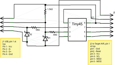
The original schematic from simpleavr.com:
Redrawn in eagle:
")
And turned into a PCB design:
")
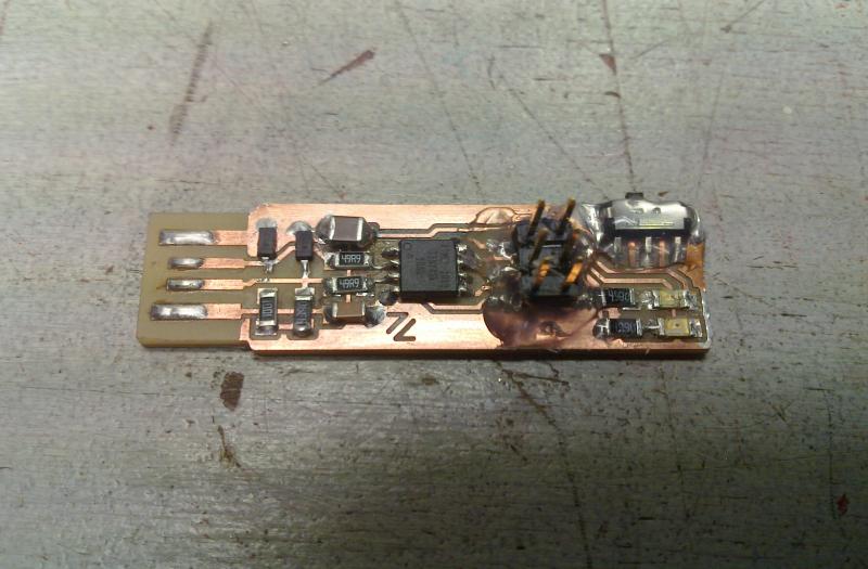
That was version 0.1, using a wrong footprint for the switch and less suitable resistor/capacitor footprints for milling. Still it worked beautifully, I have built three of these with various component configurations for testing.
For the next version I wanted to breakout the two pins dedicated to USB as well, but I was in a hurry (and to lazy) to draw new footprints yet, so it still had the wrong switch, and two 2x2 headers instead of one 2x4 header.
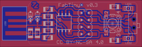
The PCB design looks like this:
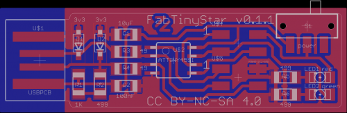
This was to be the basis for the v0.2 design, however Bas Withagen felt that it was to big for his taste (somewhat of an inside joke).
So the decision was made to rotate the microcontroller 90 degrees to save a few precious millimeters.
I also finally drew a fitting footprint for the switches available at fablab along with a footprint for an 2x4 smd header.
The new schematic for the 0.2 version:
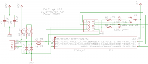
Note that the USB lines are crossed now, this happened to suit the rotated microcontroller better (see below), and as a bonus it instantly solves the minor compatibility problems with the LittleWire and DigiSpark!
[Errata: The value for R2 is wrong in the schematic, it should have been 499 instead of 49 and in hindsight 1K is more suitable when pulling up to 5 Volt]
The final PCB layout for version 0.2 (aka. the Bas Withagen Edition):
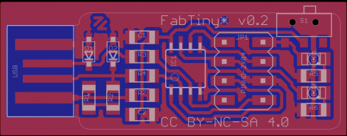
I decided to hold off on adding a reset/user button yet, because the ones at the fablab are just huge (compared to the current size of the PCB at least) and I wanted to make the thing smaller, not bigger.
And I added an optional PTC resistor to protect the USB port from getting overloaded, due to a shorted circuit for instance.
This was one of Bas' feature requests too.
As a PTC is basically a zero Ohm resistor, so from now on I guess I'll just be lying in the introduction about not having one on the board and hope nobody figures it out.
And here is the full featured version 0.3, simply named "Bas":
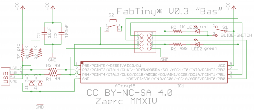
Replacing the USB edge connector with a mini-usb connector is left as an exercise for the reader Bas Withagen himself. ;)
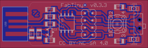
As Bas has moved to Iceland to run fablab Reykjavic, he was succeeded by Dave Gönner. Dave was in need of a version running at 3.3 Volts in order to hook up a cheap transceiver and levelshifting is a bit of a bother. So here is version 0.3.3 "Dave":
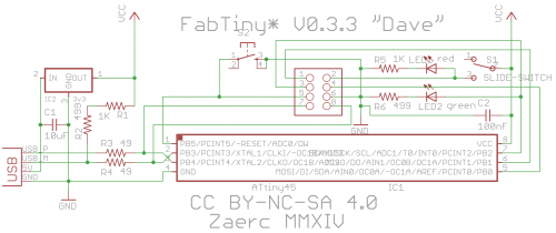
Note that running the Attiny on 3.3 Volt at 16.5 MHz will be outside of its specifications (though it usually works just fine in my experience).
As the used power regulator from the fablab inventory is rather weak, its usefullnes is somewhat limited.
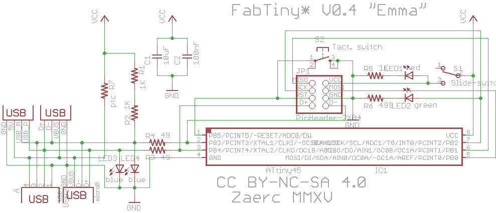
Then Emma got the job after Dave left, and she showed me that double sided milling could be done accurately, while I was still struggling with it.
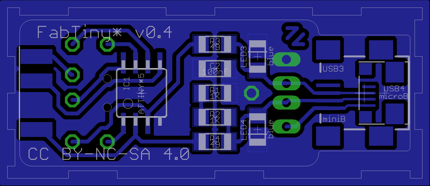
So I decided to make a double sided version as I aways wanted to use an edge connector for the pins on there anyway.
The main drawback of milling double sided circuitboards is that the vias aren't metalized through so you need to put little wires in the holes and solder them on both sides.
The method for doing doublesided we used was to put the board back into the bottom-left corner of the hole where it came from, and then subtracting the width of the cutting endmill (0.79mm for the 1/32) from the starting coordinates.
Which was rather error prone, but with this design, the subtraction is no longer neccesary!
Simply mill one side, cut it out, flip it, mill the other side and cut it out in the final shape.
The trick is in the first outline, the edge has asymetric notches exactly the width of the 1/32 endmill, when flipped they don't line up and the board becomes perfectly placed for milling the other side.
The images in the tarball for milling are labeled M1-M4 indicating the order in which to utilize them.
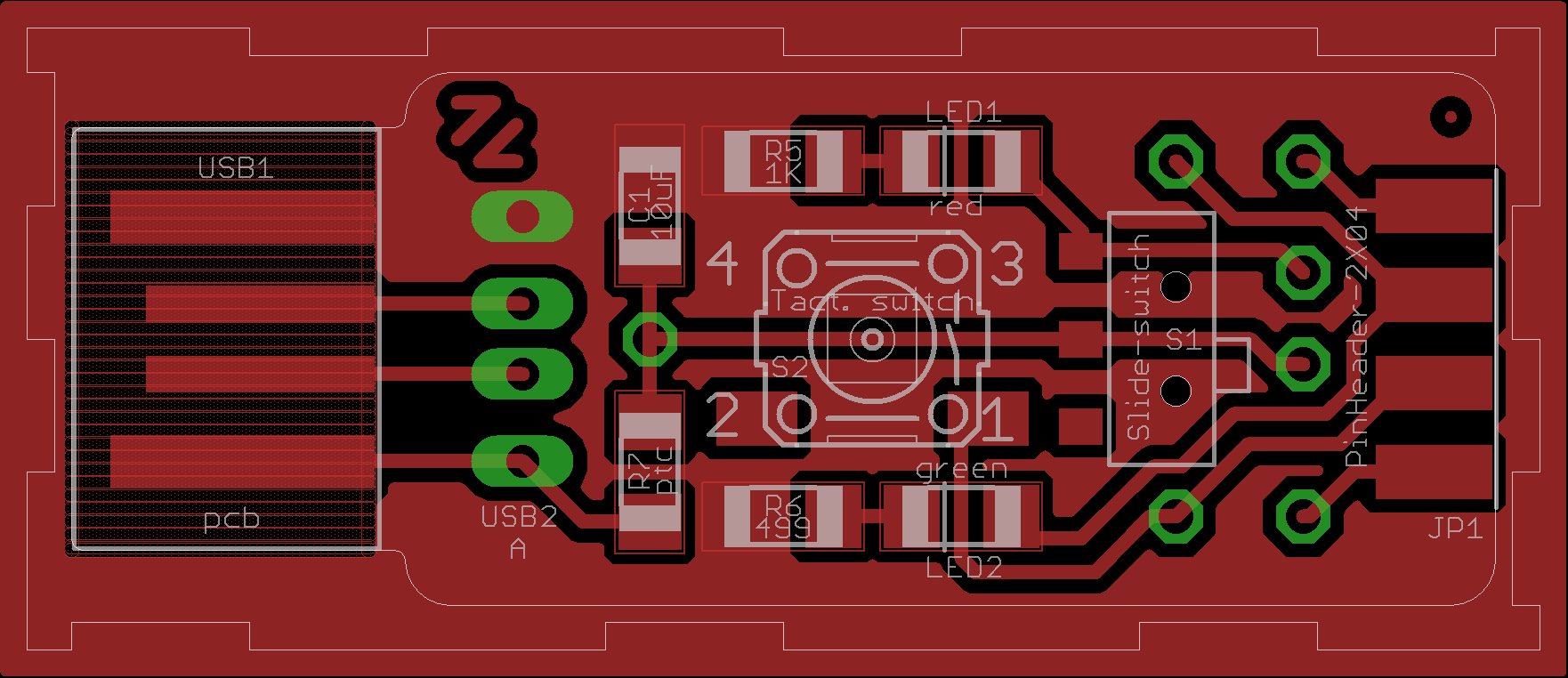
Emma is smaller then both Bas and Dave (or even BWE) also the zener diodes have been replaced with blue LEDs for a bit of extra blink (pun intended).
And to hammer the difference home, I'm putting female connectors on my boards.
While this may seem impractical, attaching a cable is as simple as clicking in a few pinheaders.
Finally a version that you can put in your pocket without the risk of hurting yourself or even worse... the board. ;)
Of course you are free to solder on male headers or even wires directly, it's your board go nuts!
cutting down the 10 pin header in the inventory and bending the feet somewhat straight is an option, usually they clamp down so well that you can program (even use) it without actally soldering them!
Now have no less then 5 different options for connecting USB: ye ole USB-PCB edge connector, a real USB-A plug or a USB cable, mini-USB and even micro-USB (I just got tired of people asking for more options, and there was room left on the bottom anyway). If you want to use the micro-USB option you'll need to get the milling just right (or be lucky). There is off course also the option to use the 1/100 end-mill, but in that case should replace the footprint with the alternative one designed for the 1/100 mill (that I also added to the fab eagle library, along with the slide-switch plus a few other parts), and generate your own PNGs for milling.
 This work is licensed under a Attribution Non-commercial Share Alike Creative Commons license