
| In this week assignment, we have to design circuit board by using software. I did not do it before ever. So need to start from downloading and Installation of perticular software. I seen lot of software for electronic designing. But I select EAGLE Because while reading tutorial I got tutorial for Eagle to install on my system. So I download it and install this freeware
Download EAGLE installer for perticulor OS from Cadsoftusa.com and Installed it. As I am using linux
Now I have to update library with all necessary componant in it for circuitry I have to design. upto I understand such concept
For circuit board we have to design, must have to design symbolic represantation or called schematic in Eagle. To do so click on 
This will let us to add componant and connect through wire. But before that there is option Grid. This should be on. This option help 
Now here from I can start my task. Upto this it was setup to drow schematic. Now I started to add componant on schematic. I found it 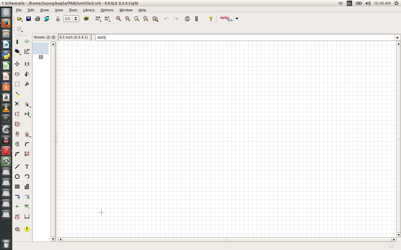 Then Libraries get open as shown in Image below. I have open fab.lbr to get my componant for circuit  Get all required componant on grid. To form circuit. 
Now after getting all componants. Select wire option with appropriat width, connect componants to form circuit chematic 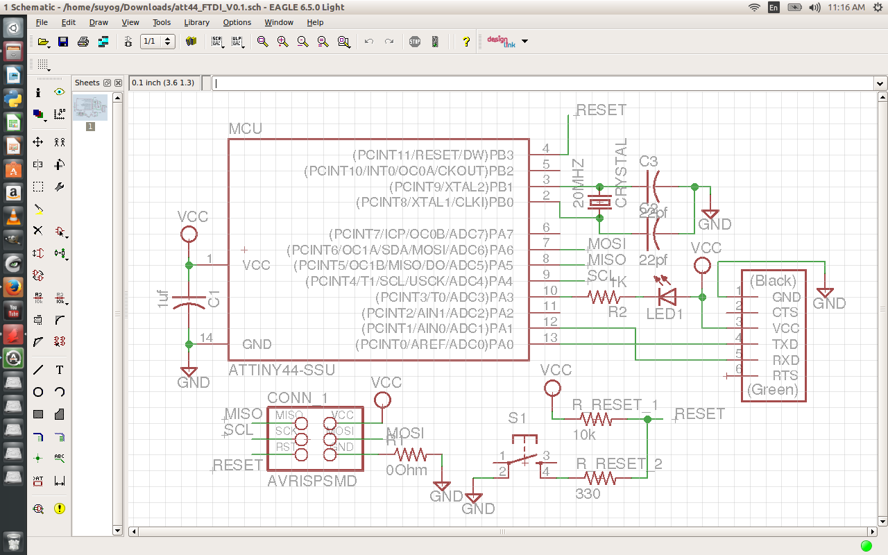
Carry out an electrical rule check (ERC) to look for open pins, etc., and use the messages generated to correct any errors. 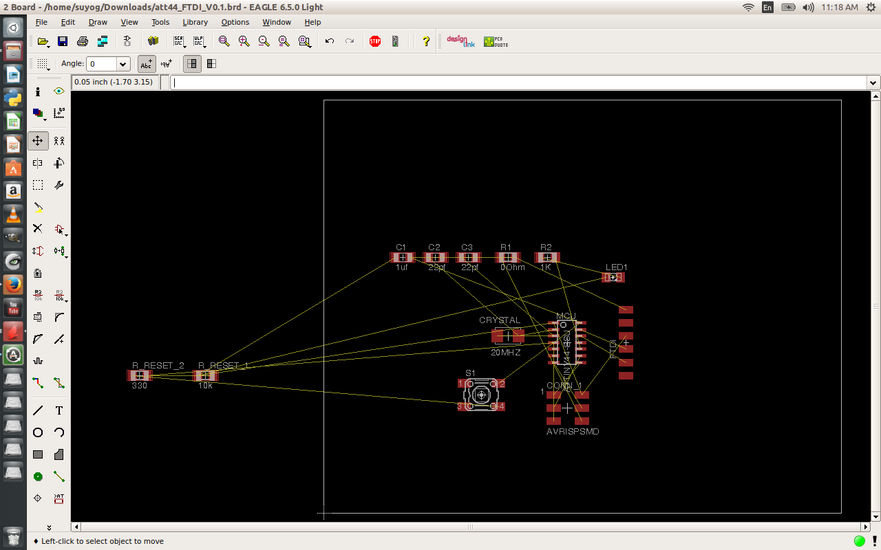
Airwires are now converted into tracks with the aid of the ROUTE command. I select Route on top. and draw traces and form circuit.  DRC and its gives green signl that allow me to go forward
Finally I select layer setting and select only required layer that is top layer n finalized a my circuit adding LED and BUTTON.  |