In this Embedded Networking and communication assignment I have to set wired or wireless communication between two processors.
I little bit scared about embedded programming. So decided to go with wired communication. That looked easy for me. Because in
Embbeded programming assignment I learnt to program a board first time. Then and also wired communication seem to be easy then
wireless communication.
I decided wired protocol to communicate between two processor. My idea was that I LDR will sence the light and generate output or
say signal for another processor. Attiny44 was the processor I learnt in week 7 according to it has analog input pins to sence analog
signals. Because LDR will produces analog input.
Hallo world was very easy circuit to understand so I used two hallo world board. One I fabricated in week 7 and another one in current
week.One holds LDR and another LED.Means LDR will sence light and generate some output to LDR board and generate signls to glow LED on
other board through board.

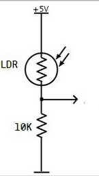
This circuit is very simple and easy to understand. When there is no light LDR resistance is ~5MΩ so simply speaking the voltage on
analog pin is very close to 0V. And when there is light present – the resistance is couple kΩ or even less for very intense light. Then
voltage on test pin gets closer to 5V. This is how LDR circuits work. So connected this divider to Attiny44 at pin no 7 analog pin and
generate some output.

I have designed Hallo world boards early week assingment. Then I
adjest design to helloword board design. Beacause I went to used that board to communicat. Beacauset`two week assignment Electronic
production and Embedded programming made easy for me. I decided to use that board for communications.
I need to design board again in EAGLE. I had to add relay on the board. So i designed that board with relay. Added componant to it

After designing the circuit board I was almost good to go for the milling process. This process is familiar to me and again I
used the 1/64 for the traces and the 1/32 milling bit for the cutting out of the board. Following the milling process I soldered
the components on the board.

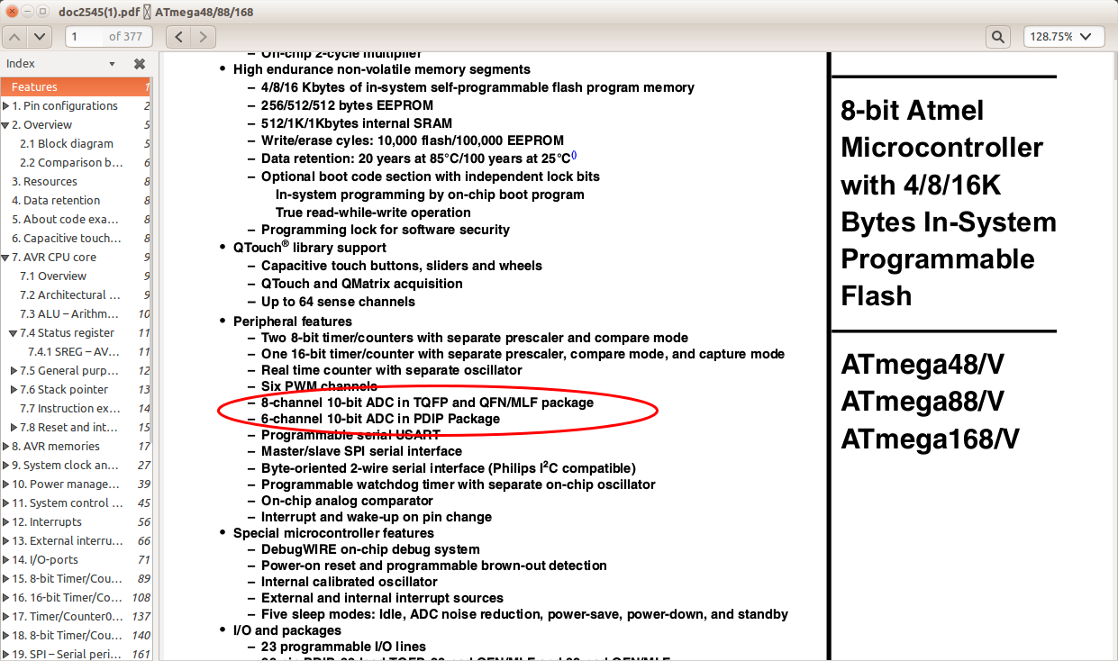
I used inbuilt ADC of microcontroller IC. that would convert analog signals from LDR to digital signals at its input.

I wrote program using arduino IDE environment. I had to consider ADC of Attiny44 for which I datashets for.
For burning program on chip I used arduino board which I used priviously hence.
So Flow of programming for LDR board was like
1) Setting analog input pin
2)Condition to generate Digital outout at output pin
3)Generate message at output.

Program for LDR board
And for LED board was like
1)Setting serial input port
2)Port to receive messege
3)Port pin where the LED will glow
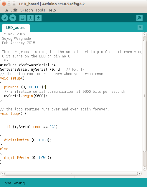
Program for LED board
I connect boards as shown in below image

Actually it is two hallo world boadr commucicate with each other. one of that board has light sensor that had been use
as input output device assigment. I had program that board such that LDR sences light and it gives high to the input pin
and ALU compairs input with value if it is high then output pin become high.That high output is the input to other hallo
world board throuh wired communication as vcc.
On second board the ALU compairs if input is HIGH. It will blink the LED on that board and vice versa. At other side this high pulse is used to drive relay also on LDR board, this Output is high that operate relay through transistor IC BC547.
I have sucessfully established communication. Between two processors. To see working video click HERE
I reffer the previous week assignment to Design(Download board files)
,mill board and LDR_board(code)
and
LED_board(code)
it.
I was feeling proud on me and start encourging myself by furthet using another sensor. But I realized still need more practice
.
I tried with IR sensor but it wasnt work. But it doesnt matters to me i decided to work on it to be sucessfull