Drawing PCB with Eagle
Drawing with Eagle is not as complicate as I imagine.
Being able to have the schematic layes out, really helps me understant the design.
(I was more the kind of people that like to connect every line in my PCB drawing first, until I try drawing a schematic myself.)

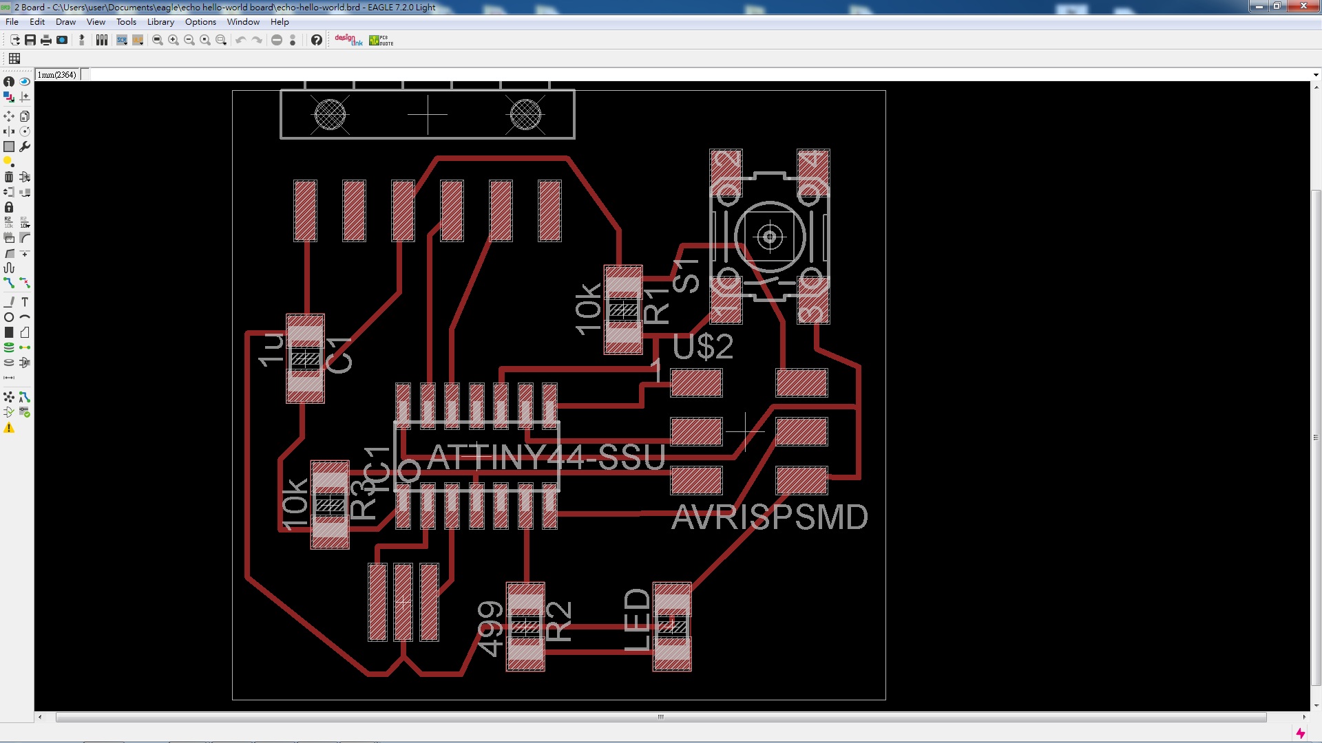
Routing the board is a bit tricky a first, so I use Autorouter to try many different configuration of the components, and than modifiy the one that I prefer the most (as for no cross line).


 The PCB on the left shows a failed attempt. Due to the incorrect milling bit size entered into the CAM software, many of the traces are not seperated. The right PCB is a succes after correct the bit size.

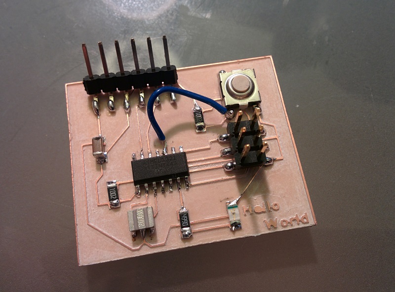
 The finished Hello World Board. I still need to get a finer soldering point and practice solding with SMD.
Notice the blue jump wire. It's there because in my Eagle drawing, one of the line in the schematic is not connected properly, and I forgot to check the error message......
The finished Hello World Board. I still need to get a finer soldering point and practice solding with SMD.
Notice the blue jump wire. It's there because in my Eagle drawing, one of the line in the schematic is not connected properly, and I forgot to check the error message......
 Going back to Eagle to fix my mistake.
 Looking forward to learn how to program this PCB next week!!!!!
Feel so much more satifying than useing a off the shelf board.
Looking forward to learn how to program this PCB next week!!!!!
Feel so much more satifying than useing a off the shelf board.