{ Fab Academy 2015 : Koichi Shiraishi }
{ Home } { Final project } { Class } { Fab Academy }
- Week 03: computer-controlled cutting -
Weekly Assignment
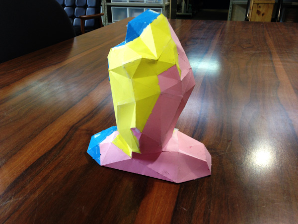
- design, make, and document a press-fit construction kit
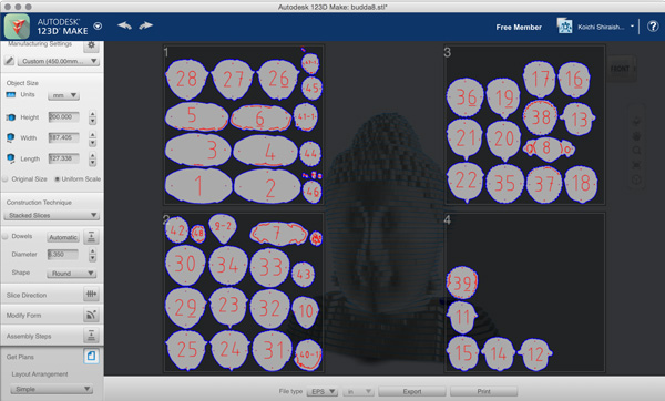
123D Make
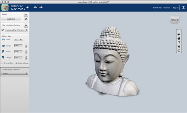
At first, I used “123D Make.”
The App is able to slice a STL data.
Step1: Manufacturing Settings
Select material size. In this case, I used cardbords of “650mmx400mm(thickness 5.0mm).”
Select > custom, and change numbers.
*”Slot Offset” is one of most important parameter. It is able to control slot friction. I input the number of “0.25mm.”
Step2: Object Size
Modify the object scale. I changed the hight scale to “200mm” easy to divide layers.
Step3: Construction Technique
Select Construction Technique. The app have 6 construction ways.
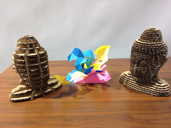
I choose “Stacked Slices,” “Radial Slices” and “Folded Panels.”
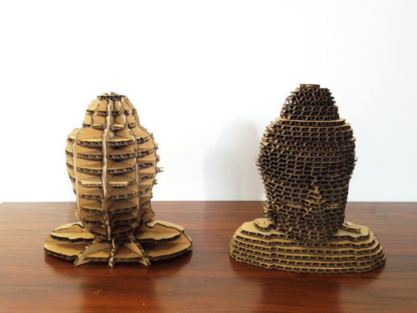
1:Stacked slices
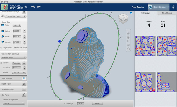
It is a technique simply stacking with no gap. If you select the paper size, The App arrange the parts into optimum position.
Check the “Dowels” box in order to make dowels. You can remove and delete dowel positions.
Change dowels “Diameter” and select dowels “Shape.”
In this case, I input “3.0” to “Diameter,” choose “Round.”
Change “Slice Direction” freely. If something goes wrong, The part have some problem is changed color to red.
If you change a “Modify Form” parameter. The form is modified to smoothly.
2:Radial Slices
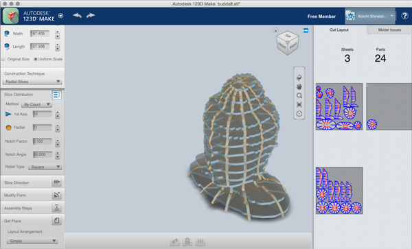
It is a technique make a press fit object. The object construct with vertical parts towards the axis, and parts radiating from the axis.
Choose a method from among the 3 options.
“Custom” is the method that you can freely set the parts distance.
“By Count” is the method that you can set number of vertical parts, and radiating parts.
“By Distance” is the method that you can set one distance of each parts.
I chose “By Count.”
If something goes wrong, The part have some problem is changed color to red.
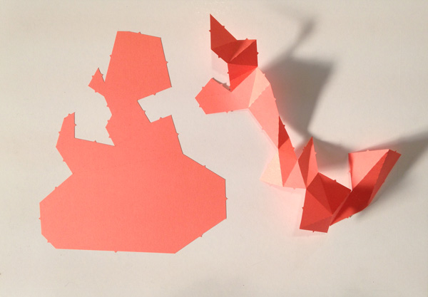
3:Folded Panels
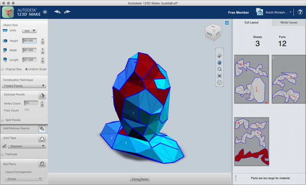
It is a technique make a development view. Input the number to “Vertex Count” box. If you input large number, The object is divided many polygon mesh. If the parts are crowded out to the outside of paper, You can divide the part by “Add/Remove Seams.” Select “Joint Type.”
Step4:Save or Print the data
You should make a Autodesk account, because you cannot save the data without log-in.
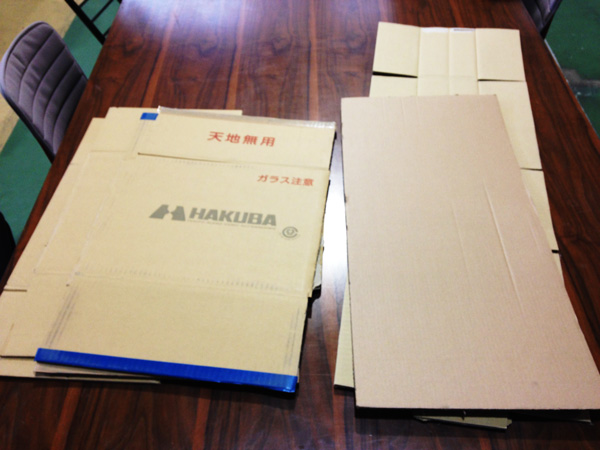
Lasercutter
I used a “Laser pro 380X” of GCC. Cut material is cardboard.
In Japan, We get used cardboads from a supermarket without payment.
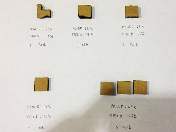
I set the parameter. and test cutting many times.
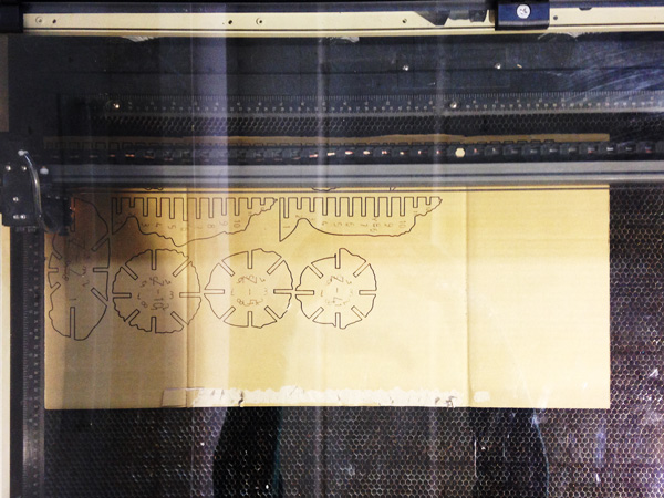
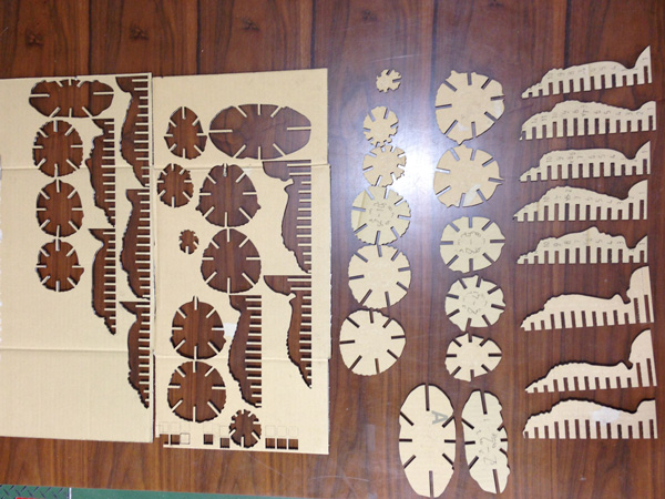
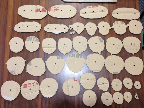
Cut files
radialslice
stackedslices
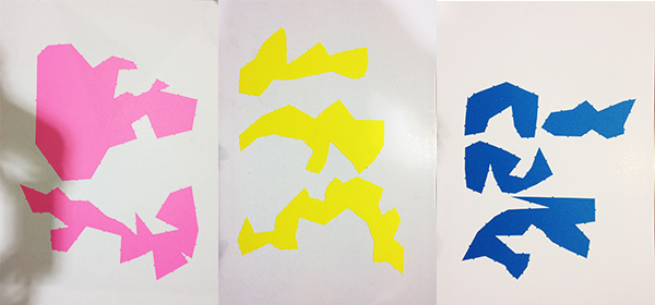
Vinylcutter
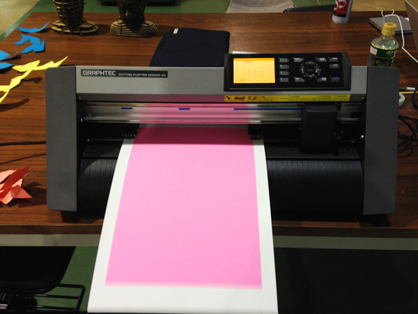
I used a “CE6000-40” of GRAPHTEC. Cut material is color paper.
GRAPHTEC machines has unique control app. It is name called “GRAPHTEC STUDIO.”
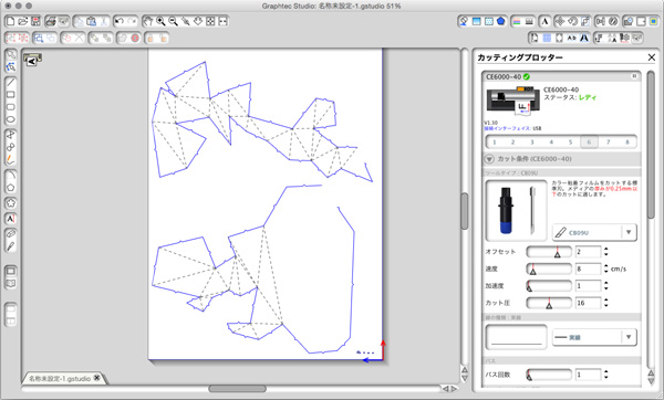
Cut files
folded_panels
Fab Modules
I tried to make screen printing plates by “Fab Modules.”
Step1: Processing picture
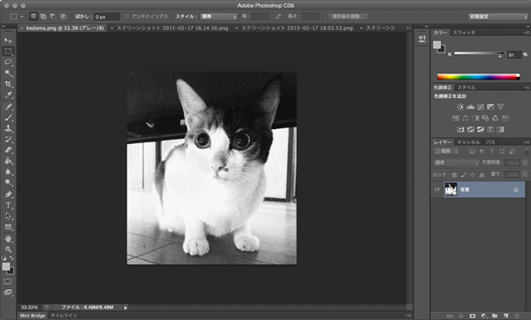
Changed color mode. (RGB> Gray scale) and correct tone.
Step2: Using “Fab Modules”
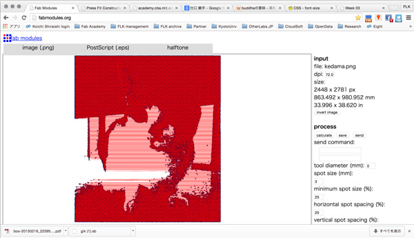
I set input image(PNG), output format(EPS), process(halftone). I Changed process parameters, but I cannot save the file.
Antimony
I installed “antimony” to use this “text” as reference.
				Requirements

				------------

				- [Qt 5.4](http://www.qt.io/)

				- [Python 3](https://www.python.org/)

				- [Boost.Python](http://www.boost.org/doc/libs/1_57_0/libs/python/doc/index.html) (linked against Python 3)

				- [`libpng`](http://www.libpng.org/pub/png/libpng.html)


				Mac OS X

				--------

				Tested on Mac OS X 10.9.4 with [homebrew](http://brew.sh/) already installed:

				ruby -e "$(curl -fsSL https://raw.githubusercontent.com/Homebrew/install/master/install)"


				```

				brew install libpng

				brew install python3

				brew install --with-python3 boost-python

				brew install qt5

				git clone https://github.com/mkeeter/antimony

				cd antimony

				mkdir build

				cd build


				/usr/local/Cellar/qt5/5.4.*/bin/qmake ../qt/antimony.pro

				make -j8


				open antimony.app

				```
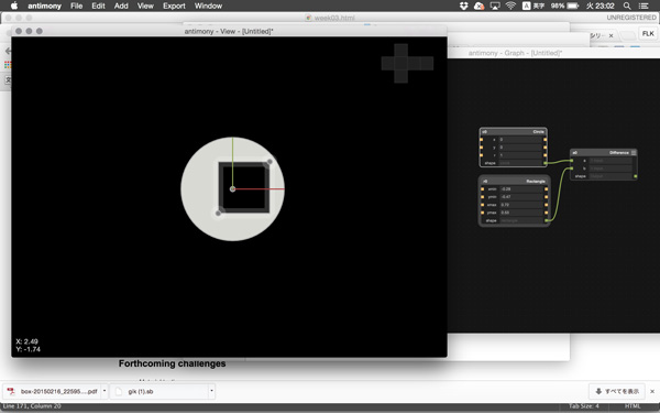
I started learning.