HOW TO NETWORK WITH FRIENDS
This week for networking did not seem particularly helpful for my final project (unless I was to separate tasks to separate microcontrollers) and networking is something I know the least amount for electronics design.
The other people attending wellington fab academy thought the same thing, and together we decided to try and make a serial bus that could all contribute to.
The first thing we did was write up a list of specifications that all of our boards would work with, so that we could all fit into the network without breaking anything. You can find the specifications in Jasmins website.
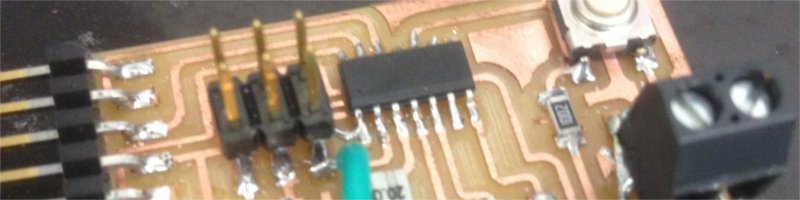
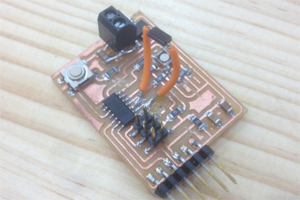
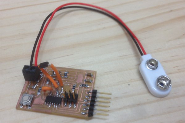
I wanted to use my breakboard from the output devices class, however, I still can't get it working. As an alternative I decided to modify my hello board from the electronics design week. The reason I needed to modify it was that the board needed to have a VCC line to the attiny to program and run the network, but not have this VCC line attached to the AVRISP header as there would be a voltage already projected through the serial line.
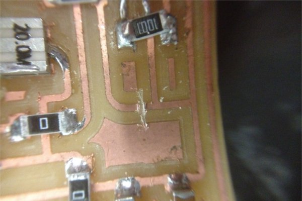
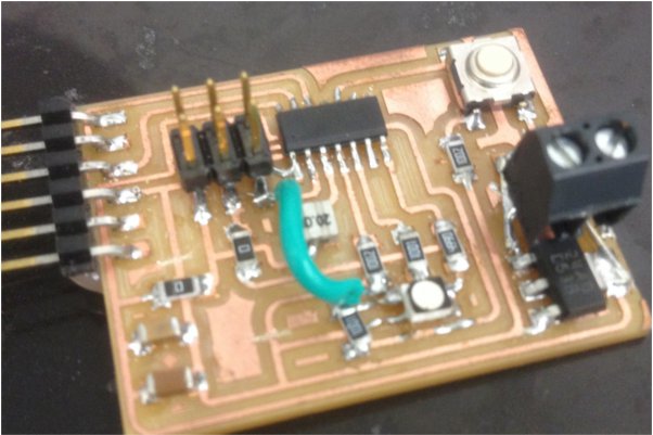
I also needed to have the RGB LED powered by the filtered power line from the voltage regulator. To Fix this, Craig and I talked and I used a knife to cut two of the traces, and soldered a wire between two of the points. Easy.
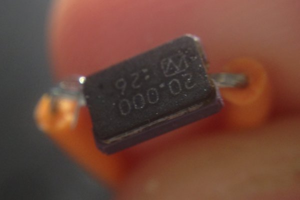
While I was doing that there was a development to the agreed upon network specifications: all the boards needed to use a 20 mhz crystal. My previous board used a resonator clock which wouldnt do. I scratched off the traces and soldered the crystal to the pins of the attiny with some jumper cables (badly). I am surprised the crystal wokred afterwards!
Fellow fab academy collegue and network engineer wizard Daniel took on the collosal task of modifying the software serial library to suit ourr needs, calling it the Wellynet library. You can find this library on Github or on my downlaods page along with my code.
As for the coding side of this project, the support from the wellynet library would cover coomunications (with the exception of adressing). It does not cover how handle the task of two different boards wanting to talk at once. In our specification plan we covered this by using a Do Not Disturb (DND) line that would be pulled high while sending a message. That way each of boards could check if another is talking. I also added code for what would happen if my board was communicated with, using my RGB LED. Unfortunately the Blue pin is also the one I had chosen to use with my AVRISP, which meant that I couldnt use it for this purpose. My RGB LED was going to be more like a RG LED.
After a bit more examination, I decided to try and use a knife and jumper wire to get the blue LED working. I might as well go for all or nothing.
FINISHING WELLYNET
I spent an afternoon with Daniel, Craig and Anna trying to work out how to impliment Wellynet in our boards. This is what I came up with:
#include (WellyNet.h) //replace brackets with pointy brackets, my website software doesnt like it.
#define COM_PIN 5
#define WN_ADDRESS 6
int DND = 4;
int redPin = 8;
int greenPin = 6;
void Action(); //a decleration of my function
WellyNet myWelly(COM_PIN,WN_ADDRESS);
void setup(){
pinMode (DND, INPUT);
pinMode (redPin, OUTPUT);
pinMode (greenPin, OUTPUT);
myWelly.begin(9600);
}
void loop(){
if( myWelly.available() ) //if wellynet is avaliable
{
int i = int(myWelly.read()); //read wellynet package and see if it is adressed to me
if( i == WN_ADDRESS )
{
while (digitalRead(DND) == HIGH){// while DND line is high, delay by adress
delayMicroseconds(WN_ADDRESS);
}
digitalWrite( DND, HIGH); //writing my adress to DND before I start my action
myWelly.print("I am ");
myWelly.println(WN_ADDRESS);
digitalWrite (DND, LOW);
Action();
}
}
}
void Action(){ //my action function
digitalWrite (redPin, HIGH);
delay (500);
digitalWrite (redPin, LOW);
digitalWrite (greenPin, HIGH);
delay(500);
digitalWrite (greenPin, LOW);
}
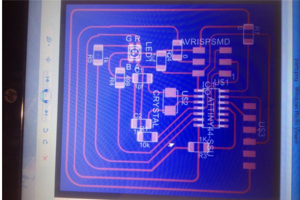
It was only when I uploaded my code to the board that I discovered it had died in the process of mutilation that was required to get it working with Wellynet. It was time to go back to the drawing board and redesign a new better suited board.
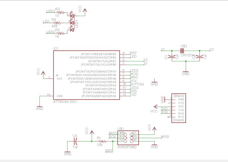
The only real change to schematic was that I knew I would run 5 volts of energy through the FTDI header, which made a voltage regulator unessecary.
After the board was designed, milled and stuffed Daniel had completely updated the Wellynet library. Because of this Craig, Anna, Jasmin, Bry and I all worked together to try and impliment it in our programming. Bry was especially helpful this time!
When it came time to link it up to the Wellynet, I learnt that the RGB LED I used was drawing too much current from the Wellynet power supply (oops) and that I needed to scale back the code, but after that it worked fine!