
LEARNING NEW COMPONENTS
Because all of our final projects need to have an input and an output device, this week is an important week for everybody. I decided on the first day that I would either use an electronic pickup , or a piezo meter to read the vibrational qualities of a plucked string. Stuart, one of the tutors for fab academy recommended I use a Piezo with the hello mic board, as this was what he did when he took fab academy and it worked. I decided to follow his advice.
The first step was to understand what was actually going on with the board. After having a look at the components and board files, I found a few new components that I didn’t understand. The first was the resistor bridge (which Neil explained briefly during the class) and the second was an op-amp.
It took me a whole day to understand what each of these components did, by themselves and then together. A Wheatstone (or resistor) bridge is a tool for measuring changes in resistance. It basically uses 2 resistors in series, and then a resistor and variable resistor in series (wired in parallel with the first set of resistors) to find out changes in impedance with measuring devices (a piezo in this case).
The Op-amp is a component that has many uses. Basically in this use, it amplifies a voltage by measuring the change in impedance from the wheatstone bridge. I wanted to use a non-inverting op-amp configuration to make sure the signal being read right. I also looked at a dc shift, to ensure that I was getting values higher than one.
However, when I looked at the hello mic board, it didn't make a lot of sense. There was a feedback resistor found in a non-inverting op-amp configuration, but also half of the resistors used in the wheatstone bridge. I struggled with this for a couple of hours before deciding to cut my losses and use the exact configuration of the hello mic board as I knew that board worked.
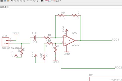
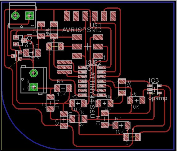
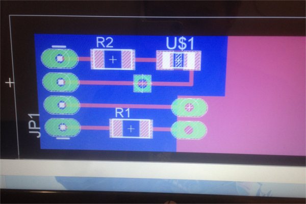
the next step was to make the schematic in eagle. I added a voltage polarity protector (with a p channel mosfet transistor- as shown in this video), a voltage regulator with two decoupling capacitors, and a resonator. I also decided to reuse part of my hello world board file to savetime on untangling the rats nest. This ultimately made the board bigger than it needed to be, but I was short on time (as I most usually am) so I wasnt too worried.
Finally it came time to program the board. I decided to start simply using the knock sketch to see if my board actually worked with the Piezo. I had a bit of trouble burning the bootloader using Ubuntu, on both mine and the fablab computers, however Jasmin’s computer worked fine. After talking extensively with Daniel, it was decided that I would go home and use apt-get to install a working version of the Arduino IDE.
Now came my second coding problem: Using Serial with an Attiny. Because the Attiny dosent have an on board serial system, I needed to use a software version of serial to get the board talking to my computer. After doing a bit of research I found that I needed two things, a serial software program and a serial to usb converter. At first I was going to use software serial, but it was quickly explained to me by Craig that the library was too big for the attiny (using 3.8 kb of the 4 that the attiny44 has!). I would need an alternative. Using this link provided a variety of options that would work well. I decided to use the USBtinydebbuger as it seemed the easiest option.
The next thing I would need was a USB to serial converter. There was alot of competition for the few FTDI cables we had in the lab, so I decided to use an Arduino Uno instead of waiting for somebody to finish. However, making a USB to serial converter in the upcoming weeks seems like a good idea.
Unfortunately I was out of time to continue programming the board, so I decided to spend the remaining time getting my documentation up to scratch. I would like to figure this out, and hopefully get my Piezo running knock, and then eventually reading the frequency of a string vibration.
CAPACITIVE TOUCH
I was struggling to figure out what electronic components to use with my final project. After talking to most of the wellington fab lab members, I decided on using a capacitive touch sensor with some LEDs.
The first step and what I will do for the input week instead of piezometer (I still cant figure out how to make that circout work), is using a capacitive touch sensor. As always I started with some research.
There are some fantastic tutorials using the Capacitive touch library. This instructables page and this youtube video are both great for walking through all the steps of making a capacitive touch sensor.
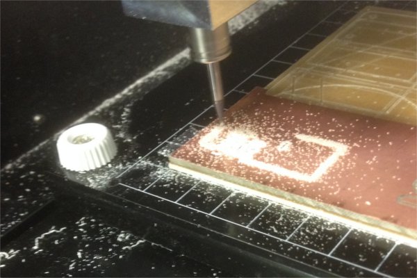
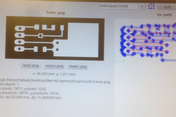
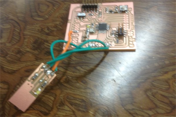
I then started to design an mill a simple capacitive touch board. It was at this point I was very thankful that our Babeduino was working. Creating this board was much quicker and easier because of it.
following the tutorials, the first thing I was supposed to do with the touch sensor was to calibrate it with a serial communication back to a computer. Unfortunately I couldnt get serial communications to work with the Babeduino (after talking to Craig the following day, it seems that this was because of a design schematic flaw, I will fix this as soon as possible). I decided to procees with an Arduino Uno.
I had no problems getting the serial communications to work, and with a 5 Megaohm resistor the capacitive touch sensor was showing values of around 6000 with a firm press. I then modified the code to work with the LED I had included to see if that would work. It did, and with a bit of adjustment I got the sensor buttom working nicely. Here is a video of the final thing: