HOW TO TROUBLESHOOT
Embedded Programming
This week has been a rollercoaster. The tutorial (like last week) took us a long time to crawl through, as we had to stop the video many times to explain contexts of words we did not understand. What I did get out of it was that now would be a good time to partition my laptop hard drive and give Ubuntu a go. With the (constant) help of Craig, I (eventually) managed to create a live usb installed with Ubuntu 12.04 and my laptop hard drive had been partitioned nicely. However when it was time to try out Ubuntu, I quickly found that the compiled drivers were having serious issues with my graphics card.
After more head scratching it was decided that using the most recent version of Ubuntu (14.10) would be more suitable and that I would just avoid using fab modules on my laptop. This worked nicely. However, when we tried to replicate the process on fellow fab academy student Jasmins computer, not only did her computer not recognise the live USB drive, it also changed the partitions on those drives to 4.5 MB, permanently. Weird.
The next issue was getting past the university firewall. I tried everything, from changing the firewall setting apt.conf file, to looking into using proprietary drivers for my laptop network card (it is hard to download those drivers using apt-get when the internet is not working). In the end I just avoided the problem and went home to update and install the software I needed. This process was VERY frustrating and took a long time, but I did learn a lot about Ubuntu, apt-get and other command line software like nano.
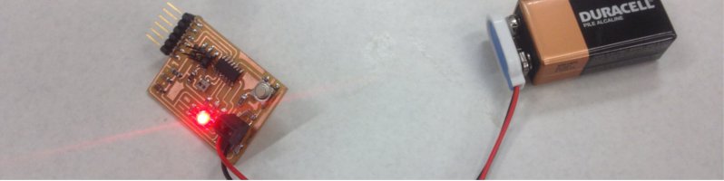
At the same time that this was going on, I tried to start setting up and using the Arduino IDE to initially program my board. I downloaded the board files ( I couldnt find the FTDI drivers for Ubuntu, and then I read (link:s) that Ubuntu already has them installed, handy! When it came time to burn the bootloader into the board (what I assume is using the fuse memory), the Arduino IDE said the board was not recognised by the computer. I immediately knew that this was the result of my ISP board being faulty, and when I tested burning the bootloader with another ISP, it proved to be true. I will need to either troubleshoot and fix, or completely redo my FABISP in the future.
Another problem I had when setting up the Arduino IDE on ubuntu, was that my computer did not have java, which means the program wouldnt run. installing the open java development kit with this tutorial meant that arduino now ran without a hitch.
I took a break and read the (dense) AVR microcontroller data sheet. I skimmed and picked 3 things that stood out to me.
- Opertating voltage is 1.8V - 5.5V, awesome
- The data rentation is 100 years at 25 dgrees calcius, this inst the most useful fact, but is rather awesome anyway
- an external power reset will happen even if the clock inst running, this could be good to know for trouble shooting.
Now came the time to upload the program. Using a mixture of the LED example sketch, and this RGB sketch, I was able to use my small amount of arduino knowlege to modfy the program so it used a switch to cycle the RGB LED between 5 different colours. The only thing that confused me was that the switch pin had to read LOW to start the LED cycle. After asking, this was a result of the way I arranged and soldered my switch on the board. Here is what my sketch looked like:
int redPin = 8;
int greenPin = 6;
int bluePin = 5;
int buttonPin = 3;
int buttonState= 0;
#define COMMON_ANODE
void setup()
{
pinMode(redPin, OUTPUT);
pinMode(greenPin, OUTPUT);
pinMode(bluePin, OUTPUT);
pinMode (buttonPin, INPUT);
}
void loop(){
digitalWrite(redPin, HIGH);
digitalWrite(greenPin, HIGH);
digitalWrite(bluePin, HIGH);
buttonState = digitalRead(buttonPin);
if (buttonState == LOW){
cycle();}
}
void setColor(int red, int green, int blue)
{
#ifdef COMMON_ANODE
red = 255 - red;
green = 255 - green;
blue = 255 - blue;
#endif
analogWrite(redPin, red);
analogWrite(greenPin, green);
analogWrite(bluePin, blue);
}
void cycle(){
setColor(255, 0, 0); // red
delay(1000);
setColor(0, 255, 0); // green
delay(1000);
setColor(0, 0, 255); // blue
delay(1000);
setColor(255, 255, 0); // yellow
delay(1000);
setColor(80, 0, 80); // purple
delay(1000);
setColor(0, 255, 255); // aqua
delay(1000);
setColor(0,0,0);}
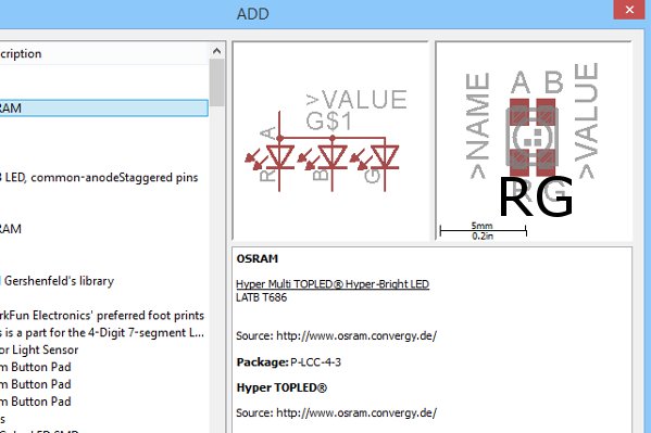
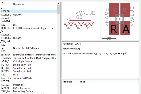
Another strange issue was that the Sketch was only showing 3 of the 6 different colours in the cycle. It seemed that each colour that needed the green LED to light up was just skipping to the next color (which did not require the green LED). After about a day of confusion I had a look at this board from the output devices class. I noticed that the part I used in the fab eagle library (from last years archive - there is no link in the 2015 tutorial) is mislabelled, with the VCC and green LED pins being swapped.
This is only the OSRAM part (with smaller copper pads for soldering). To fix this just rotated the LED 180 degrees so that the VCC pin matched up with the vcc input. I then swapped a few of resistors over so that they were all correct too. This meant that my Arduino code worked right, although the pins were pulled low to get the cycle function working. I will upload the final sketch in the downloads page:
Next I tried to get a working knowledge of C for AVR programming, I tried to use forum tutorials like this c programming avr tutorial on hackaday and this syntax explanation of C, in order to get a basic understanding, but I ended up just getting very confused. The one video that actually helped me alot was Elliot Williams webcast: Beyond the arduino, programming in C.
I found this video really helpful to explain basic concepts like the built in peripherals and
the hardware, as it related to my small amount of arduino knowledge.
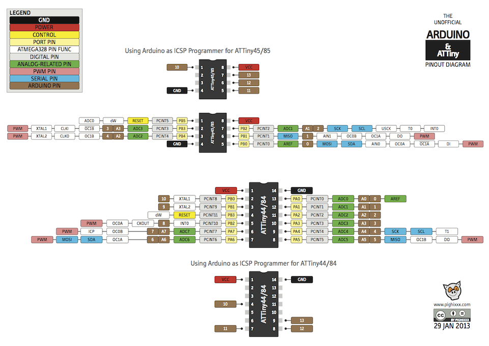
I tried importing the code from Scott Ziteks website (an amazingly well documented website that I looked at constantly during this week). I changed the pins to the right ones using this Attiny cheat sheet.When I compiled the code in the Arduino IDE, it came up with the error that header.h wasnt referecned. To fix the problem I tried to download the C libraries for avr programming from avr libc. It proved difficult but I sucsessfully found the right doenload. After I referenced the libraries in my sketch properly and it still wasnt working right, I changed the syntax to use quotation marks. this worked right and the program complied without a problem.
#define F_CPU 20000000UL // 20 MHz
#include "avr/io.h"
#include "util/delay.h"
#define bit_get(p,m) ((p) & (m))
#define bit_set(p,m) ((p) |= (m))
#define bit_clear(p,m) ((p) &= ~(m))
#define BIT(x) (0x01 << (x))
int main()
{
//SETUP
//Button is on PA3
//LED is PA7
bit_clear(DDRA,BIT(3)); //clear DDRA bit 3 makes PA3 (pin 10) an input to monitor my pushbutton - I don’t need pull-up resistor
bit_set(DDRA,BIT(7)); //Set DDRA bit 7 makes PA7 (pin 6) an output to control my LED
//LOOP
while (1)
{
if(bit_get(PINA,BIT(3)))//button is not< pushed
{
bit_set(PORTA,BIT(7));//LED is on
}
else // button is pushed
{
bit_clear(PORTA,BIT(7));//LED is off
_delay_ms(10);
bit_set(PORTA,BIT(7));//LED is on
_delay_ms(10);
}
}
}
However when It came time to upload the code, I got no response.
I had run out of time at this point. Overall I was pretty content with the amount of progress I had made, so I decided to stop there for this week and focus on getting my website up to date.