THE ART OF VISUALISATION
Computer aided design (CAD) software is only as good as the person directing it.
That said, CAD is a very very large term. As an industrial designer, CAD software needs to help me design, help me visualise objects to an audience and allow me to take my designs to a manufacturer. That means it has to be easy to use, make things look relatively pretty and have no issues with the model upon export to machine.
My preference in CAD software would definately have to be Rhino. This is because:
- I know how to use it.
- It seems to work best for me.
- Rhinos are ok I guess?
but seriously, when choosing CAD software just choose the one that will help you achieve your goal, and go with it. Now onto this weeks project. Right away we were told to examine our idea and try and map it into a touchpoint map. Now you (being an avid reader) should know about my design criteria and target market(which you can find here) but I have come to a few decision. Im going to try and design a flat packed guitar made out of a cardboard and resin composite. The reasons for this are:
- This could make the body extraordinarily cheap to build.
- The finish could be the resin, cutting down on costs of finishing the material.
The cons being:
- It might sound really bad.
- Like, totally awful.
If you think of a chain of materials, judged by their acoustic qualities with timber being at one end and MDF being at the other, then I am afraid corrugated cardboard is on the wrong end of that scale. I aim to start the first cycle of the cyclical design next week by making a sample material from which I can test the acoustics. if not then it is back to the drawing board.
from here I got my ideas down on paper which looked like this:
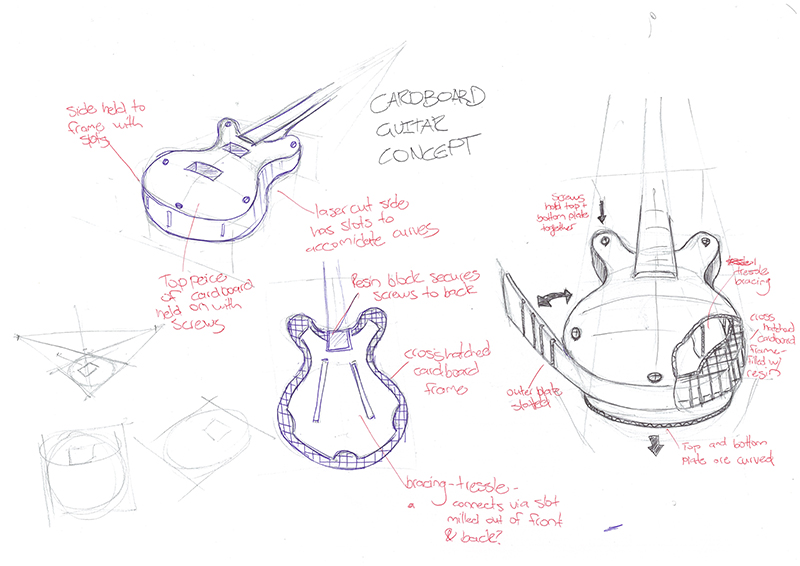
The design (which at the moment is based off a hollow body/ Gretsch type guitar) is by no means fixed and will change if the material doesnt work or if it makes more sense to make a different type of guitar.
At the moment the reason for this type of design is that it seems to be a good middle ground between using the acoustics of the material and construction and using a pickup to drive the sound. Besides, hollow body guitars are frickin sweet!
We were also encouraged to create a journey diagram for our designs. Since the core experience should play out exactly like a standard guitar (to the musical user) I decided to create one that revolves around the fabrication process. This is it:
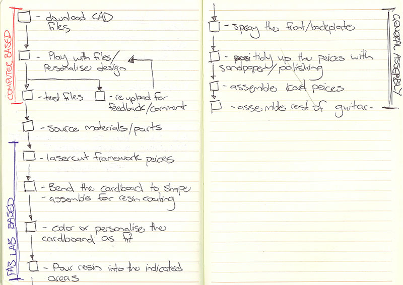
I imagine that this diagram will change and evolve as the project does. It might be interesting to continue updating and uploading the journey as it does. But for now the main variable in the journey is the materiality.
it is worth noting that I purposely left any extra electronics out of the diagram in an attempt to keep it at the core experience.
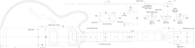
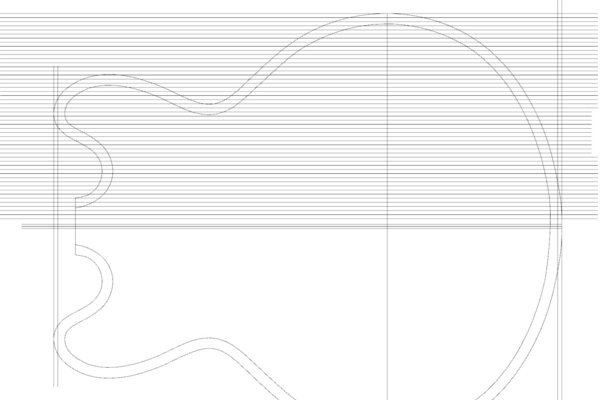
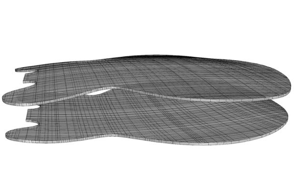
From here I moved onto constructing a 3d model. I needed a place to start. I made the decision pretty early on this week that I wanted to visualise the cardboard construction method this week, and thus I started with the plans for a Gibson es 335. I used the exsisting measurements (which I assume were close enough to correct) then imported the documents in real space 3d to Rhino.
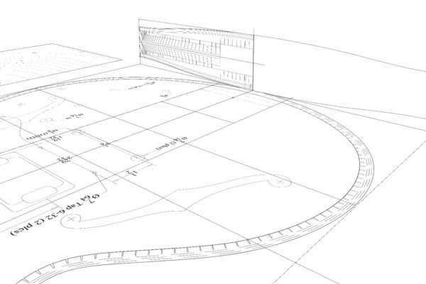
I encountered a dilemna:the cardboard frame. My plan was to take this model into next weeks assignment (to create a press fit laser cut mold) so I could contruct a prototype out of cardboard. The problem was I do not know what cardboard thickness to use. It seemed to me better to construct the model parametrically so that I could save on time in the future.
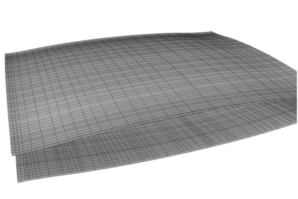
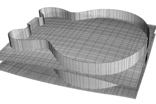
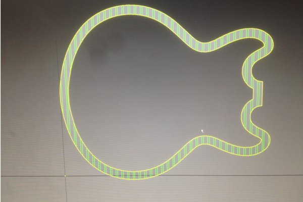
In the meantime, I thought it best to construct the top and bottom parts, which shouldnt change too much. This is how I did it:
From here I could take a few routes. I need to model my project parametrically and playing with a few different moddelling software was part of the assignment. The question is what one to choose in my limited amount of time.
I started with Antimony becasue it was reccomended as a highly versatile program in the lecture. Unfortunately I didnt have a mac or linux computer that was behaving nicely, so after an hour I deccided to cut my losses and move onto inventor.
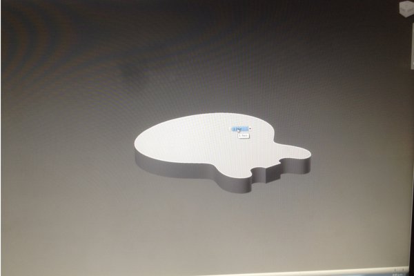
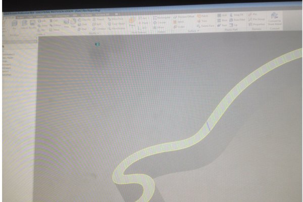
Inventor was interesting. The workflow of the software was very different from what I am used to (in my experience with rhino). Basically you start with a basic vector shape, creating a solid from it, then adding features by repeating the process on parts of the exsisting solid.
However, I needed the model to be parametric, so that the trenor box frame could accomidate different cardboard widths.
I started by importing the basic vector from rhino so I had a starting point to work from. I quickly found out that in inventor there is a difference between a spline and a vector curve (the spline has active control points).
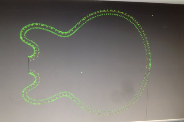
I then learnt the lesson of taking the model one step at a time in inventor. Instead of extruding the difference between outer and inner layers, I had to do it in 2 different steps.
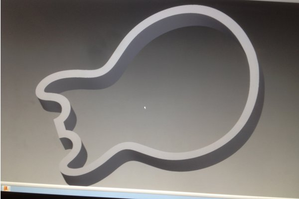
Here is where I thought the parametric functionality could come in. In inventor, I only found a way to parametrically control dimensions of specific shapes. The idea for this model was to create a series of 4mm thick boxes and evenly space them throughout the model. I would then subtract the spaces inbetween those boxes from the solid shape, effectively creating a crosshatch pattern.
I got as far as making the lines evenly spaced before I realised I needed to split them so that they would only subtract from the shape itself. When I split the lines all of the parametric functions got deleted. I just couldnt make it work.
At this point the computer I was using gave up on me and inventor crashed multiple times in sucsession. I decided that was enough inventor for the time being.
Next on my list was grasshopper. I have had one single training session on it aabout 2 years ago. At the time I appreciated how powerful it was.
Unfortunately the learning curve is very very difficult. I wanted to make a torsion box frame with adjustable thickness of the material, as well as the distance between walls. Here is my progress:
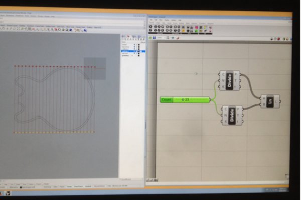
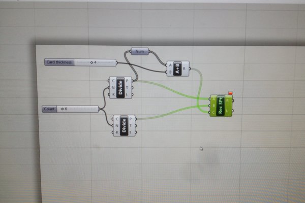
I managed to make adjustable lines in a box, with the number of lines dictating the distance between them. The image on the right is my progress with attaching a rectangle with adjustable width in to those lines.
Overall I tried out varyious different programs, but the one I would like to investigate further would be grasshopper. I think I will try and use it next week to finish my parametric model of the guitar.
VECTOR FILES AND VINYL CUTTING
The first part of this weeks assignment was to vinyl cut some stickers for the curtain infront of the kitchen (or compost lab). Having had quite alot of experience with this process, I thought this could be a good oppurtunity to experiment with inkscape.
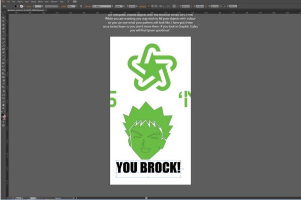
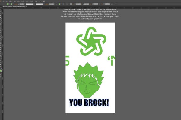
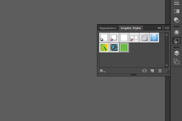
The first part of the process was opening the template file, which as you can see by the images below, contained the craphic style that would emulate the vinyl we were using.
For the sake of tutorial I thought I would do a brief documentation of the things I already know in illustrator.
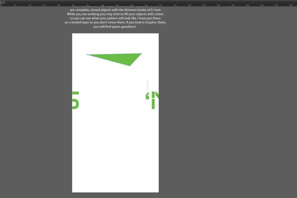
The first thing I did was complete a vector loop with the pen tool
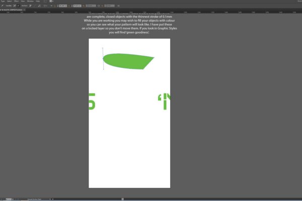
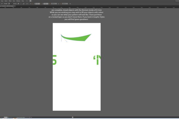
Then I used the move handle tool (located under the pen tool) to show how that can change the curves.
I then imported a monochrome image in order to live trace the imagine into vector curve. It was as simple as selecting the image, choosing the black and white logo option (it was coincidently a black and white logo), then cliking licve trace.
It was worth noting that live trace created vectors of the image, the negative space and also the border.
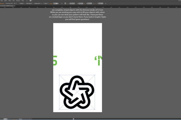
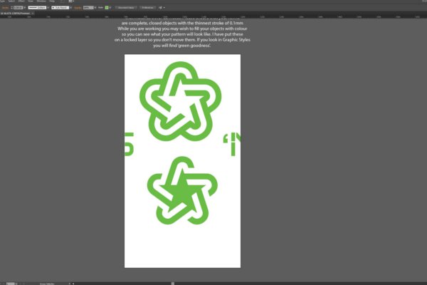
Finally I used the pathfinder window (found in the window menu) to merge two overalapping vectors into one shape.
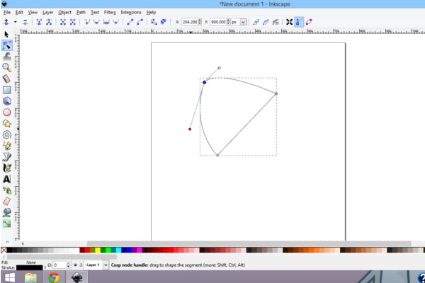
From there I downloaded Inkscape, and repeted the things I had done in illustrator to get an idea of the program. I found Inkscape very easy to use and not a large program to run at all. For the use of creating vectors for simple machining, the interface is very intuitive!
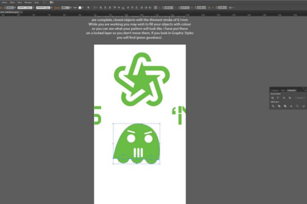
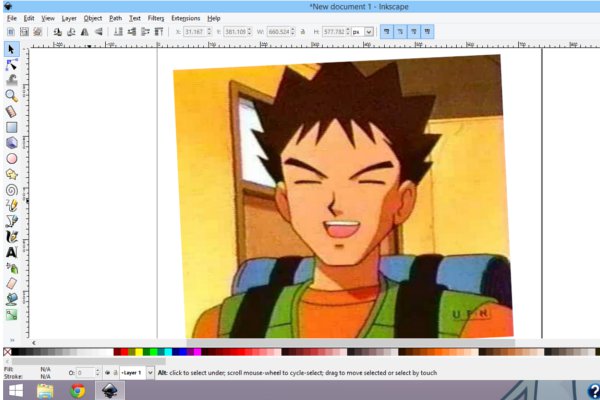
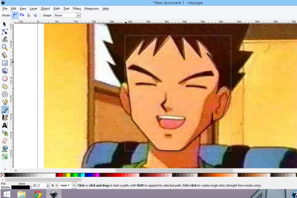
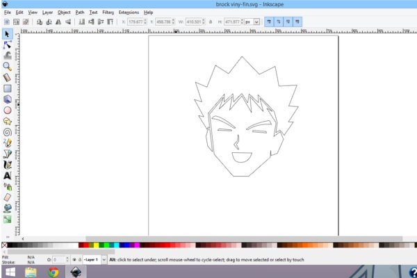
I was ready to do my final vinyl cutting! I got a picture to trace, and using the pen tool, traced and Image that would represent the picture in 2 colors.
Finally I imported the vinyl cutting vector into illustrator to turn text into vectors (which I could have done in Inkscape but I was working in illustrator for the template anyway). To do that, all I had to do was right click on a peice of text and select create outlines. Easy.
The last thing to do was cut it out of the vinyl cutter. I simply loaded illustrator on the vinyl cutter computer, and used the roland modela plugin get the sheet size from the vinyl cutter. I used the same plugin to cut out the vinyl. A very easy process.