Goal
For electronics design, I have designed and built a dedicated custom board for Input Devices. This board needs to be fairly compact as I am intent on using it as the 'object vended' sensor for my final project.
Part Design
Unfortunately, I could not locate an extant example of the Eagle parts representing the Optek OP280 IR LED or it's spectrally matched sibling the OP580 photodiode, so begins the task of making some new symbols!
Footprints
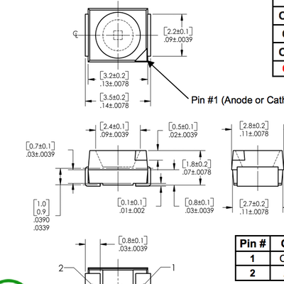
The first step in creating the footprints for the comonents is to consult the mechanical drawing included in the datasheet, now given that both parts I am going to be creating are PLCC-2 I could have used an existing footprint from one of the standard Eagle libraries and simply reused it, however given I am intending to manufacture this board using the Modela, I felt it best to start from scratch and create a footprint optimised for CNC milling.
Creating the Schematic
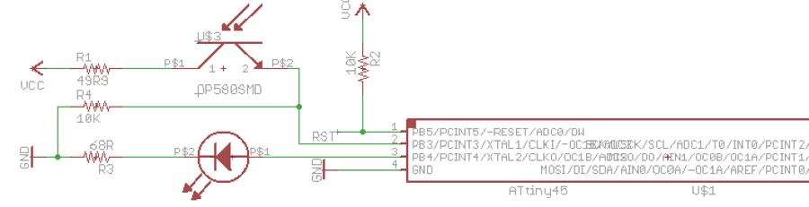
I used the Hello Reflect board as a starting point for my design but I decided to modify it a bit to reduce the size. I had no need for the FTDI header and so replaced it with a small 4 pin dual row header.
4 Pins, Why?
Well, I wanted to have the sensor capable of operating in 2 distinct modes, the first mode would be as a 'smart' sensor, communicating information back to a master device using I2C, thus the 4 pins were for VCC, Ground, SCL and SDA.
The second mode was as a dumb sensor, with the μController on board toggling the 2 pins to indicate the state of the sensor, the intention being 1 pin an active high and the other an active low to help in high noise environments.
Board Layout
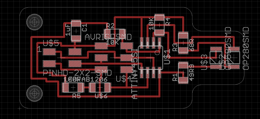
The starting point for this board layout was the location of the LED and Phototransistor, they would need to be quite close to one another in order to work as intended so I moved them to the right hand side of the work area in the layout that I thought made sense.
I next moved the μController and ISP header onto the board and made a first attempt at routing the 6 requisite pins, moving the pullup resistor for the reset line onto the board in the process.
I had originally chosen to omit the visible light LED from the board to save on space and money but decided after a while that it was ultimately too useful to have such an inticator on the sensor itself, this did require some enthusiastic use of the ripup tool followed by some more caution (and expletive laden) use of the routing tool.
Programming
The board was fairly simple to program, I opted to use the Arduino programming environment as I intend to use this sensor as a demonstration for my classes and the Arduino environment is a gentle introduction for the new students starting out with μControllers.
I have more details of the programming of this board on the Input Devices page.
Design Files
- The library I created with the Optek parts in it is here.
- The original Eagle design files are available for download here.
- The Arduino-based sketch used for testing is here
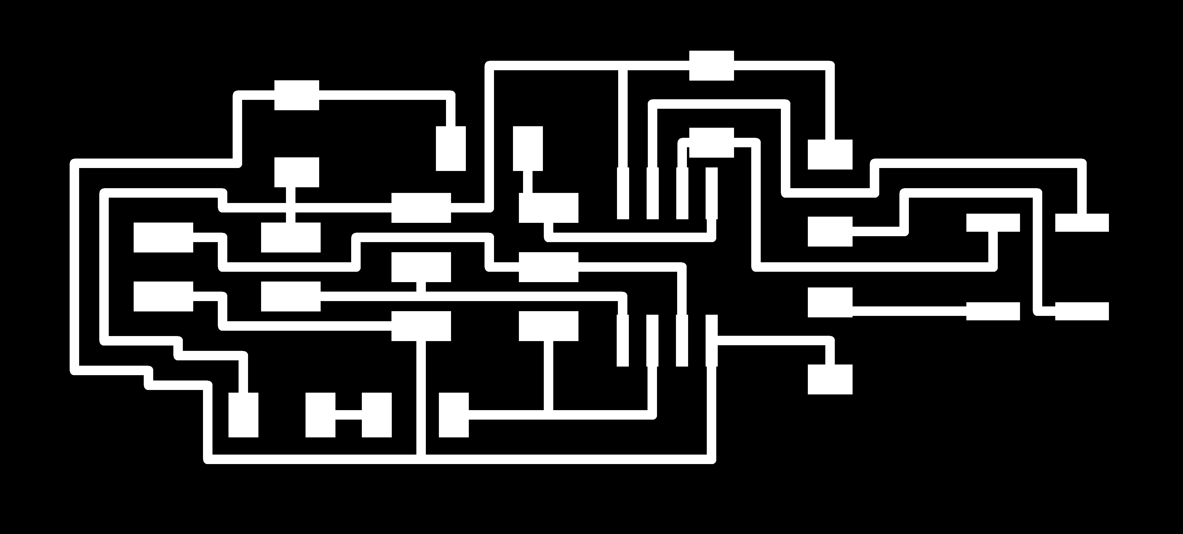
- Images ready for milling: Traces and Cutting Out.