CAD Software
As the project I have in mind is a complex mechanical system I need software capable of creating assemblies of components in order to perform basic simulation and fit testing during the design process.
Candidate: Autodesk Inventor
Autodesk Inventor is a stack based CAD package with all of the capabilities required. Inventor can run on Windows and MacOSX and is free for academic use.
Candidate: Dassault Systèmes Solidworks
Solidworks is one of the most popular and capable CAD packages in use worldwide, it has all of the functionality required for my project and then some. Solidworks has one of the steeper learning curves in my list.
Selection: Solidworks
I have selected Solidworks as the main package for my project based on its capabilities for constructing complex assemblies and performing advanced simulation on all components. Additionally, there is a selection of Solidworks experts available to me locally should I hit any major stumbling blocks.
Drawing Parts
Picking a plane
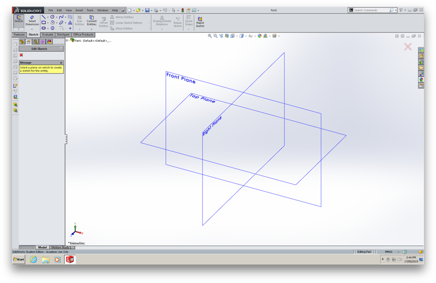
When starting to draw in Solidworks, you first need to pick a plane to draw on, this is largely dependant on the orientation of the part you're drawing but it's helpful to keep all of your parts oriented 'correctly' for the final assembly
Sketching the Basic Shape
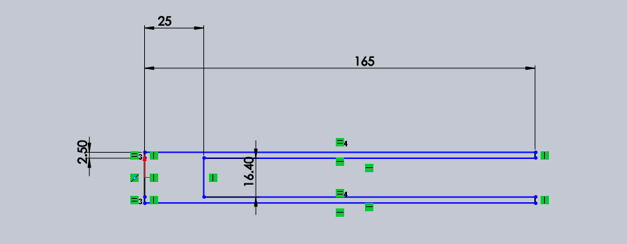
As a starting point for my project I decided to design the basic mounting system for a standard SMD component reel, to this effect I started with mechanical drawings from Vishay Semiconductor and set about drawing a half crossection of the reel, By drawing in this way I can simply create the 3D shape of the reel by performing a revolve operation.
Note:
The dimensions in this drawing are not just for show, unlike many CAD packages Solidworks is most efficiently operated by drawing first with rough freehand dimensions and then using the Smart Dimension tool to specify the exact measurements for each component of the sketch.
Let's Get 3 Dimensional
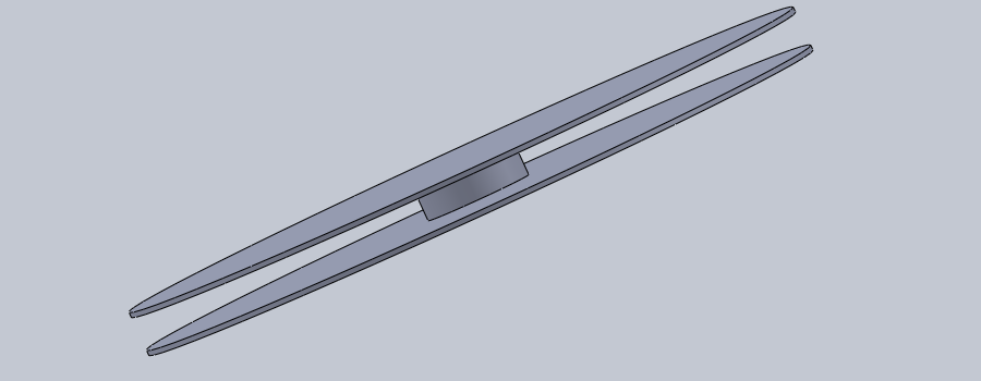
The revolve operation takes the shape we draw earlier and pivots it in 3D space around a given axis, in our case the axis we will rotate it about corresponds to the leftmost solid line in the sketch.
Time to Subtract
To create the central hole and the gaps in the sidewalls I need to do a subtraction operation, but first I need to create a sketch on which to base this, so time to draw the outline of the central hole:
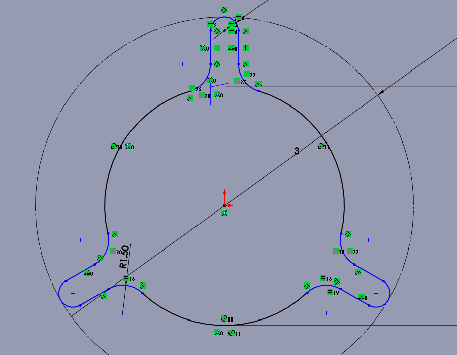
The dashed lines in this sketch represent construction lines, these are parts of the drawing that are not intended to be part of the final shape but rather are simply there as reference geometry to help in building the intended shape.
Materials
In order for many of the simulation functions of Solidworks to function each part must have the correct material set, in this case the reel is made of black ABS plastic. By setting the correct material I can begin to estimate the mass and other mechanical properties of the part, additionally correctly configuring materials and their associated appearances makes assemblies much easier to work with by making parts visually distinctive (It also makes your renders look much better.).
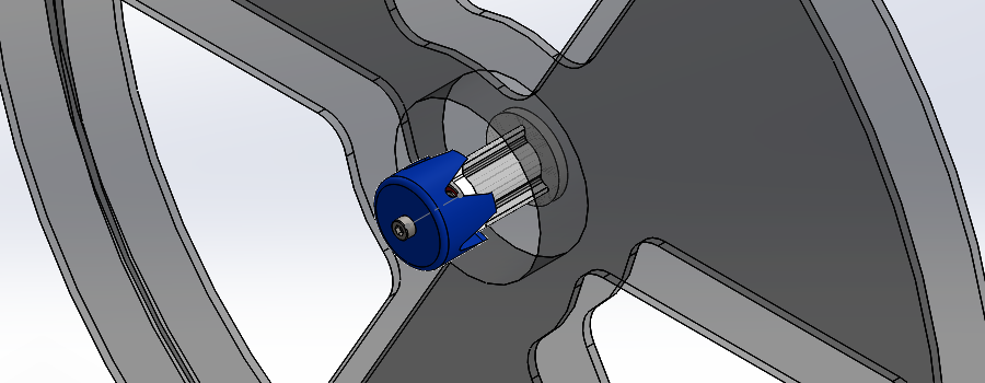
Starting out with Assemblies
One of the most powerful features of software like Solidworks is the ability to combine parts into complex assemblies complete with functioning mechanical constraints. To start out with I have modelled the retention mechanism for the SMD reel as well as a 623 bearing and M3x50 cap screw. By combining these into an assembly and constraining them appropriately I can start to build a model not only of all of the individual parts but of how they will fit together.
Parametric Design
For my work on learning parametric design in Solidworks, see Week 8: Make Something Big.
Design Files
- A tarball of the solidworks design files is available here.