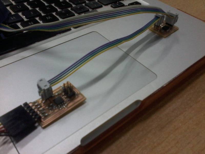
I chose to make two boards one bridge circuit and one node node circuit. In this video observe how the serial communication between the lap top, the node, and bridge are connected and how they work.
LED
Microcontroller
Resistor
Capacitor
Phototransistor
ISP header
FTDI headerS
Not to scale
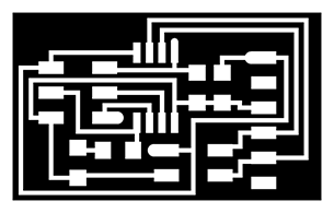
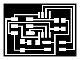
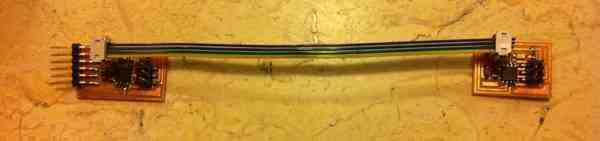
The trace below on the left side is the bridge circuit and the trace on the right is the node circuit.
Now it is time to mill the boards and solder the components to start the network.
|
|
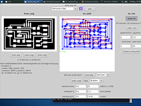
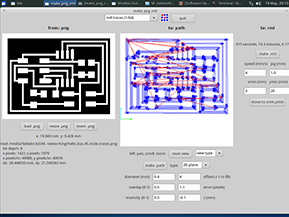
1- Open the software (Fab Modules), set it on the output format Modela RML and the input format png
2- Insert the interior trace, using the 1/64 inch diameter end mill to mill the electrical traces
3- Fix the board using super glue, or double sided tape
4- Prepare the machine, zero the X, Y, and Z axis, and start milling
5- When you are done with the trace, insert the outer trace to cut the traced circuit from the excess material, using the 1/32 inch diameter end mill
6- Finally, prepare workbench and components
NOTES:
 |
 |
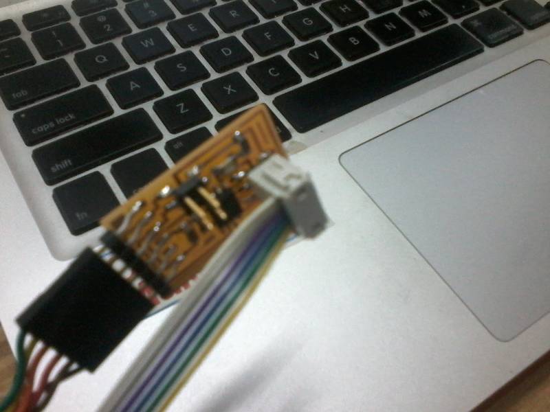
Here are the bridge and the node after soldering connected and ready to be programmed.
N.B: Fisrt I need to burn each boar's IC bootloader, and program each separately.
Using Python language
First I need to burn the bootloader of each;
Program each separately;
and finally build the network and serial communication.
 |
 |
Here is the code uploaded successfully
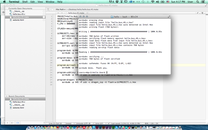
Phython
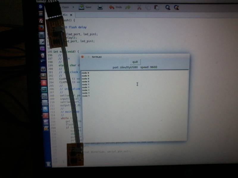
Here is the serial monitor indicating the given commands
When 0 is pressed the birdge is connected and that is indicated by the LED and when 1 is pressed the node is connected.
Both LEDs blink once indicating a command taken, then one one the LEDs blind according to which commande hace been given 0 or 1.
To see how it works check the video at the top of the page.
 mariamwaelgado@gmail.com mariamwaelgado@gmail.com |
 http://mariamwaelgado.wix.com/ http://mariamwaelgado.wix.com/mariam-wael |