DC Motor
ATtiny44
Voltage regulator
Resistor
Capacitor
ISP header
FTDI headerS
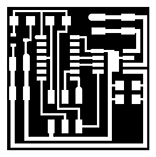
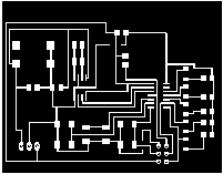
Here is the DC motor circuit trace
using the Modela
This time i used the 0.001 inch end mill to come up with neat and clear traces since the board is small similarly to the LDR input board in assignment 10. Below you can observe the neat tracing of the board.

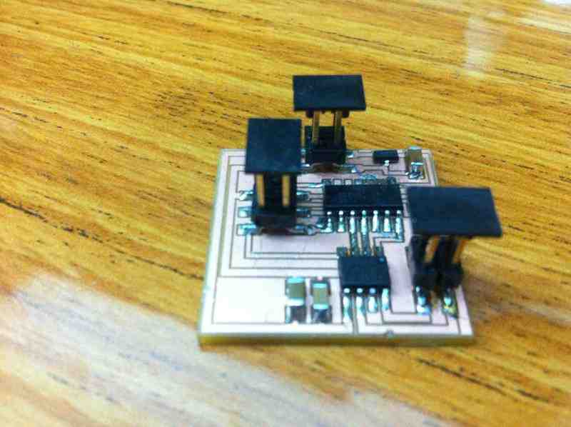
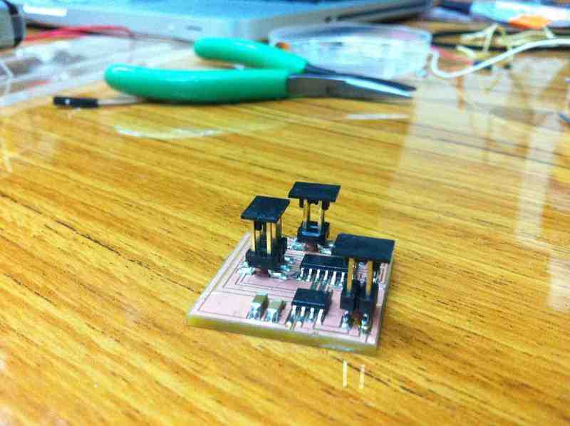
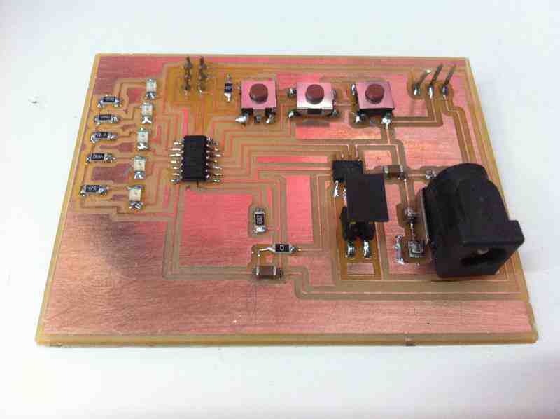
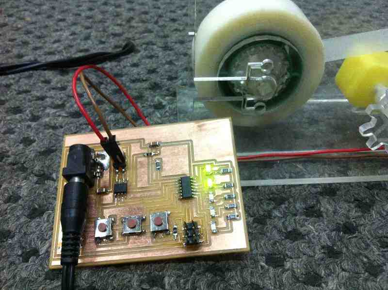
Here is the outcome of the DC motor circuit board.
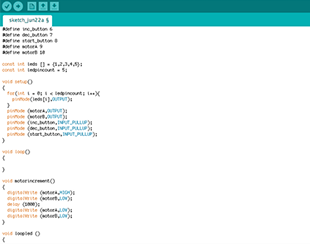
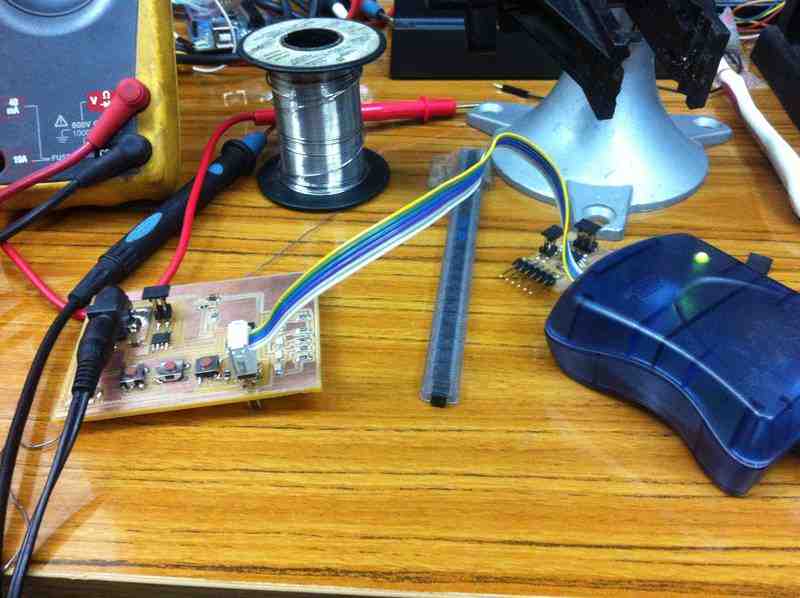
Now It is time to program the ATtiny44.
 |
 |
After making sure that the DC motor (output) works, I started developing the final project controlling board that contains one DC motor, 3 push buttons, and 5 LEDs.
On the upper left photo is the circuit trace of the final project controlling board.
On the upper right side is the board after soldering all components.
Below you can find the programming arduino code, and if you want to see it up close find it in final project>> electronics page.
In this project i have the DC motor and the LEDs as OUTPUTS.
 |
 |
 |
 |
The board contains:
3 push buttons (incrementing, decrementing, and roll)
Incrementing: Increases the turning time of the DC motor to suspend a longer part of the tape.
Decrementing: Decreases the turning time of the DC motor for suspension.
Roll: Is the order given to turn the motor.
5 LEDS (indicating how long will the suspention be according to the adjustments using the incrementing and decrementing buttons)
The DC motor that does all the work
 mariamwaelgado@gmail.com mariamwaelgado@gmail.com |
 http://mariamwaelgado.wix.com/ http://mariamwaelgado.wix.com/mariam-wael |