
Phototransistor (LDR)
ATtiny45
Resistor
Capacitor
ISP header
FTDI headerS
This is the circuit for the LDR
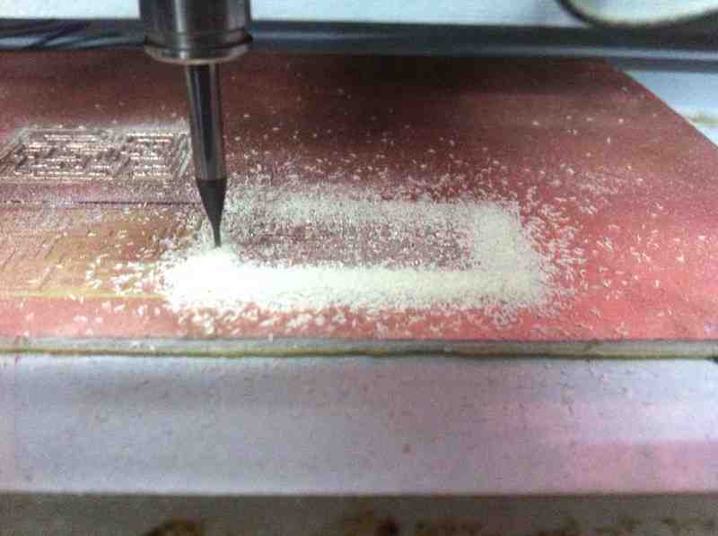
using the Modela machine
Because the board is too little and contains detailed traces it requires a 0.001 inch end mill, but here, i used a 1/64 inch end mill which was not accurate enough to trace clearly and neatly.
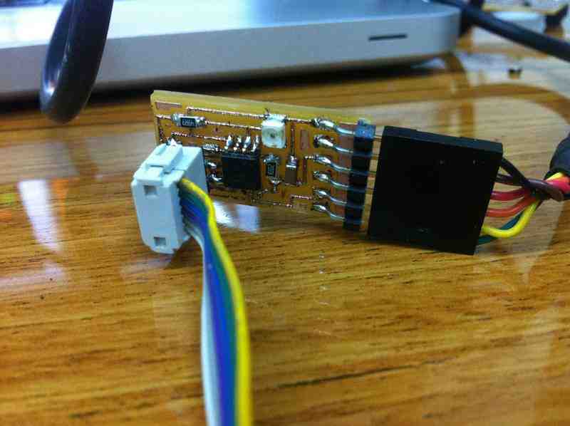
After a long hectic detailed soldering, it is now time to program it and test it.
As you can see the board is very small in relation to the gift, and the traces are bumpy because of the inaccuracy of the end mill; however, it still works.
 |
 |
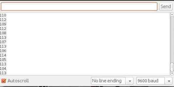
Using python and serial communication, I programmed the IC. After uploading the code, the serial monitor showed different values according to change in light resistance value as shown below.
After programming the LDR circuit, I tried to use it with processing as an indicator for the LDR given values.
At the bottom of the page you will find a video of the processing LDR indicator.
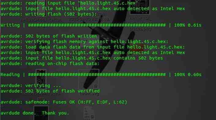
Here is the serial monitor showing different values of the LDR input, and
the latter is the code uploaded successfully to the IC.
 |
 |
I used this input device in assignment 14, Interface and Application Programming. A software that indicates the changing values detected in one of the previous screenshots in an interactive way. When I prevent light from the phototransistor the brightness of the red color decreases and vice versa. For more info visit assignment 14 page.
 mariamwaelgado@gmail.com mariamwaelgado@gmail.com |
 http://mariamwaelgado.wix.com/ http://mariamwaelgado.wix.com/mariam-wael |