Scott Zitek - Fab Academy 2014
3D scanning and printing
Week 5 Assignment
The assignment for this week is to design and 3D print an small object that could not be made subtractively and to 3D scan an object. If possible, we could also print the object we scanned and maybe even make our own scanner.
Designing and printing a 3D object
- I had several ideas for 3D objects to design. However, since the part was going to be small I decided to keep it simple. I used SolidWorks to design a 1" x 1" cube that I subtracted a cylinder out of the center. I then drew a spiral down the middle and used a sweep to make a spring shape.
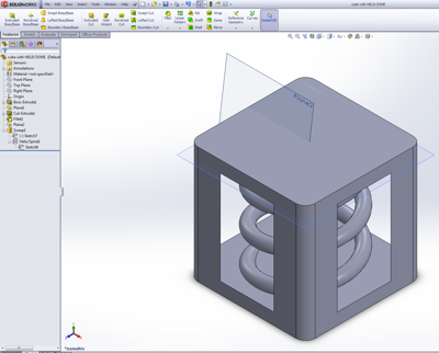
3D cube draw in SolidWorks
- I then exported the design as an STL file. I opened the file in Catalyst EX, the software for our 3D printer. I used Catalyst to orient the part for optimal printing and then created the path. If there is a prolem with your STL file, this is when Catlayst ussually warns of reverse normals etc. It was able to generate a path for my part without any problems.

Catalyst shows all the paths the machine will follow, blue lines represent support material and red represent modelling material.
- I added the part to the "pack" to show the software where in the machine I wanted to print the part. I then loaded a build plate into our Dimension 1200es SST 3D printer, checked to make sure I had enough material for the job, and pressed the print button.

For a commerical machine, ours is incredibly unrelaible.

This is what it looked like when printing. The part is being built in the back right corner. The support material and the build material is black and the machine has tinted windows, so it might be hard to see.
- When the part is done printing you need to pry it off of the build plate. The base of the part and other places will be covered with support material. The support material is brittle enough to break off some places but parts often need to be soaked in a heated circulating tank to disolve away the support material from out of all the nooks and crannies. With soluable support material it is possible to print parts with moving components.

This is what my part looked like when it came out of the printer.

After removing the support material the part looks much better. The finsihed 3D printed cube with a flexible spring shape in the middle.
3D scanning using the NextEngine scanner
- I reluctantly decided to use our NextEngine HD scanner to scan a metal car. The NextEngine scanner uses the array illumination method of 3D scanning. I tried using this scanner several times in the past and it has been very tedious and time consuming. My past results have been fun to look at but not nearly good enough to do anything with like 3d print them.
- Since the computer we use for the NextEngine scanner had failed last year. I had to download and install the NextEngine ScanStudio SD software. I was only able to download what I assume is the version of software that was available when we bought our machine. The software was not compatible with 32-bit Windows 7 but I eventually got it to work. I then needed to install the NextEngine ScanStudio HD version of the software. I am not sure why I didn't have that option in the first place. I got everything up an running. I found that I can only run the software with a full administrative account. Even then, I frequently recieve warnings about low memory when ever I run the software (the computer has only 2GB of RAM).

I will be scanning this metal car which we normally use for vacuum forming demonstrations.
- Since my part is shiny metal, I coated it with talc powder. Unfortunately, the talc also gets in the nooks, crannies, and details, I think it reduces the quality of the scanning of these features. When ever I touch the part, it removes some of the talc. Note to self, don't where dark clothes when doing this next time becuase there is talc everywhere.
- I mounted the car standing up on end onto the NextEngine turntable. I manually moved the turntable to center it in the view of the camera. I had to experiment a little to make sure the car fills the camera frame but will stay completely in view as the part turns.
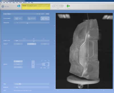
I configured ScanStudio for a full 360 dgree scan with SD quality (2.5k points/inch). This scan sequence is estimated to take approximetly 25 minutes.

The turn table rotates the object so that it can be viewed from different angles and then stops while the object is being scanned.

This is the scanner scanning the inside of the bottom of the car. Even with a good coating of talc, the bottom did not scan well.
- After about 25 minutes of bright lights, whiring turntables and laser beams, I check the results. The software automatically stiched all the different scans together. However, because of the way the car was mounted there is no front or back bumper. Just a big hole. There are also small holes on the sides of the roof and the bottom doesn't look correct at all.

Notice that there is a hole in the front of the car where the bumper should be and you can see some of the turntable.
- I used the trim tools to select the parts of the turntable and fixture there were scanned in and then erased them.
- I repositioned the car on the turntable so the laser and cameras could see the front of the car. I used the bracket mode to scan three views. It scans the initial view and rotates the object to a lttle to scan the left and right. I had to repeat the process again for the back of the car.

This is how I scanned the front and back of the car.
- After trimming the front and back scans. I aligned them with the first scan by using various colored locator pins. Once the scans are aligned, you can set various options to fuse them all together into a single object.

Notice the color dots are used to align the same point on the scans on the left and right sides of the screen.

This is what the point cloud looks like for the completely scanned object.
- I used ScanStudio to define the base of the object, top, front, and origin. Then I limits of the ScanStudio software. All of the other CAD features worked only in demo mode and attempting to use them triggered advertisememts. All I could do was export STL and OBJ files. Everything else costs more money.
- Importing the STL file into SolidWorks seemed pointless. I couldn't really edit the mesh to fix it.
- So after at least a couple of hours of talcing, scanning, trimming, aligning, fusing, etc. I have an interesting model on the screen that I can rotate to look at from any angle. This is the point at which I normally stop. The model model is not water tight or perfect enough to print and the commercial software to fix, edit and convert the point cloud into something useful can be very expensive.
Mesh software
This week in lecture, we learned about several different free software packages for inspecting, fixing, and editing the output files from a 3D scanner.
I installed the following software packages:
- AutoDesk Meshmixer
- Materialise MiniMagics
- Meshlab
- Netfabb basic
These software packages varied greatly in ease of use, capability, and availability of helpful documentation for beginners. Materialise MiniMagic 3.0 was only really good for testing the STL for errors. This could be useful if that is all you need and you want something that is simple to use. However, the other packages can do this and so much more.

There is a really impressive number of options in the pull-down menus of Meshlab.

For example, Meshlab can display lines to indicate the directions that normals in the object are facing. The end result s a hairy looking part. With this view, it was possible to see that the surfaces inside my car had normals facing in both directions.

netfabb basic was able to fill the hole in bottom of my car automatically. Unfortunately, the resulting bottom is not flat and the weird surfaces are now hidden inside of the part.

AutoDesk Meshmixer offers a descent balance of easy of use and capability. As the name implies, is has the ability to easily mix meshes. In this example, it was easy to add a gorilla head and arms to my car.
Observations on the mesh software that I tested:
- All of the mesh software that I tested easily detected the errors in my scanned STL file. All but MiniMagic had some abilities to fix it.
- I think every one of these software packages crashed at least once when I was testing them. I used the software on two different computers and they both had some problems.
- To use these software packages it really helps to know the concepts and vocabulary of 3D graphics and geometry. Terms like vertex, vertices, normals, meshing, textures, etc. are used often.
- I suugest saving often using different filenames, just in case you need to go back to something before you modified it. I never did figure out how to undo an action in Meshlab.
- I think netfabb basic offered the best inspection tools. It also has powerful automatic tools for fixing problems.
- I felt Meshmixer was the easiest to use software for editing the 3D form. However, the editing is not very precise like CAD. It is much more of an artistic process like virtual scuplting.
Printing my 3D scanned part
After scanning the metal car and using the mesh software packages to create a watertight STL file, I was able to print a 1/2 scale car.

Catalyst EX recommended printing the car standing on it's rear bumper.

This is what the bottom of the car looked like when it came out of the printer. The ABS model material is black and the support material is a semi-transparent dark brown color.

Original metal car next to 1/2 scale 3D printed "copy"
Photogrammetry
I also installed 123D Catch on an Iphone and used it to scan a metal horse head hitching post. This was much quicker and easier than using the NextEngine scanner.
- After installing the free 123D Catch app from the Apple App store and creating a 123D account, I simply followed the directions as the app walks you through the process.
- I set the horse hitching post up on a stool in the middle of a brightly lit room. This way I could easily walk around all sides of the object and take pictures of it from above and below.
- I followed the on screen indicators to take pictures of the object from many different angles, making sure to take pictures of every aspect of the object as yo walk around it. (eg. under the chin of the horse head.). I took about 40 pictures.

This is an example of one of the pictures I took using the 123D Catch application. Notice orange safety cone. Lots of different things in background seems to help align pictures from the various different angles.
- The app then uploads the pictures to AutoDesk for processing. This can be a lot of data so a wifi connection is needed. For some reason, I had to restart the upload processes several time because the app said that my wifi connection was lost. I have not had wifi connection problems with apps.
- After the images are processed, you get to preview and frame the result. You can then decide if you want to share your 3d creation with the public or keep it private.
- I made my model public so if anyone that wants to, they can download the 3D model information in STL and OBJ format. The files can be found at http://www.123dapp.com/obj-Catch/Metal-horse-head/2166688
- I download the STL file and opened it in Meshmixer. I was able to easily fill the bottom and a few small holes to make a part that should be able to be 3d printed. The entire process was much faster and easier than using the NextEngine scanner. The quality of the 123D Catch part looks better but it is not a fair comparison unless I scan the same part with both units. It appears that 123D Catch really strength over the NextEngine is its ability to scan big things like people and cars.

This is the end result. The software automatically ignored almost everything except my intended subject. However, a little bit of the orange safety cone did sneak in the final result.

I was able to load the STL file created by 123D Catch into meshmixer without any problems. I used meshmixer to inspect the part and automatically fix the errors. The part is water tight and ready for 3D printing. Note, you can't see the orange from the safety cone because the STL format does not include the textures. The cone is still on the bottom and should be trimmed off.

If you download the OBJ files of the horse it will come with the texture files. This is an example of one of two texture files that the software wraps around the 3D shape. To me it looks like the pieces of a broken pottery horse.

Cardboard version made using online web version of 123D Make. The online app kept locking up when I tried to do anything else. So I installed the Windows version of 123D Make.

With very little effort, the Windows version of 123D Make was able to make cut files for the laser to make the 3D object out of stacks of foam.

With a few changes to the options on the left side of the screen and 123D Make creates the cut sheets for a radial design of the horse. Note the red is used to indicate the parts in the design that have errors.
Back to index