Networking
Task:
design and build a wired &/or wireless network connecting at least two nodes
Description:
For my final project I would like to make the lamp standalone, for this a colleague of my told me that I could try the nRF24L01(+) 2.4GHz Wireless Transceiver. Through this communication I want to give a colour input to the lamp representing a certain need of the user (concept to be found here).
What did I do:
- Research the nRF24L01(+) 2.4GHz Wireless Transceiver
- Design two circuit boards
- Milled out boards
- Trying to program the board
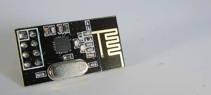
nRF24L01(+) 2.4GHz Wireless Transceiver:
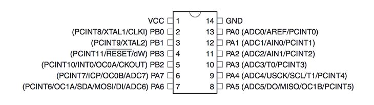
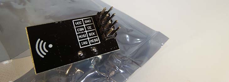
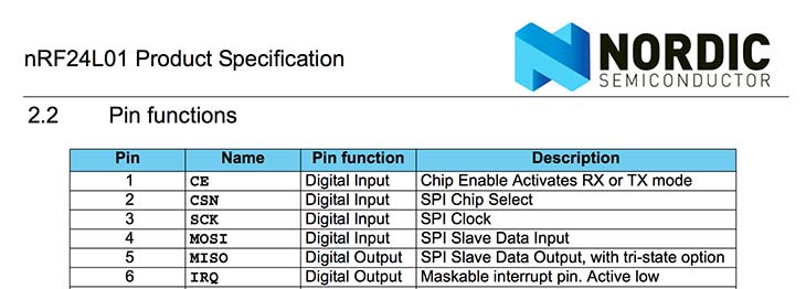
The transceiver is a pretty cheap solution for a network. The transceiver runs under a 1.9 to 3.6V supply range, which means that it works well on a coin cell, this was necessary for the standalone lamp. For the board connected to the computer I needed a 3.3v regulator. The transceiver has 6 connection pins but you can do it without the interrupt request (IRQ). I decided to use it because the attiny44 has an IRQ and I had enough pins for the other functions I needed. I checked out the mirf library for the ATTINY84 to connect the pins on the right pins.
Design two circuit boards:
After checking all the connections and if I had the right amount of pins I started designing the board. I needed one board that would transmit my code to the receiver.
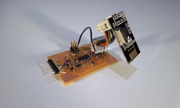
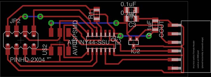
For the transmitter I used this components:
- ATTINY44
- 6 pin header
- 2x 4 header (cut from a 2x 5 header)
- programming header
- 3.3v Regulator
- 3x 0.1uF capacitor
- 0Ω resistor(jumper)
- 10K resistor (pull-up)
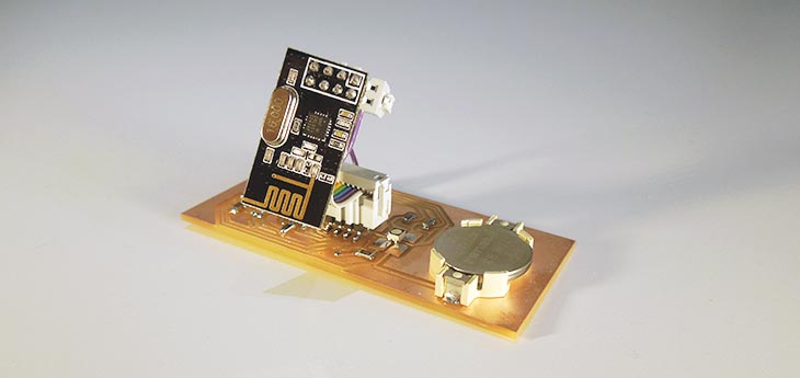
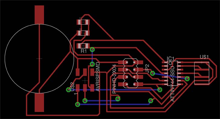
For the receiver I used this components:
- ATTINY44
- Coin cell holder
- 2x 4 header (cut from a 2x 5 header)
- programming header
- 3.3v Regulator
- 3x 0.1uF capacitor
- 0Ω resistor(jumper)
- 10K resistor (pull-up)
- RGB LED
- 3x 500Ω resistors
- I copied my other design but I forgot to take the 3.3v regulator off. I don't need the regulator anymore, because the board will use a coin cell battery. My solution a solder jumper.
I had some problems with my design in Eagle, some of the labels weren't connected well and I found out after milling and soldering the board. I redesigned my board for next time but my dirty solution for now; Wires.
Milled out boards:
The milling went not well in the first try, this because of the machine's setup. Eagle cut a little bit of my border so it did not cut out my board well. I used Photoshop to edit the image so it would be more clear for the machine.
Trying to program the board:
For the programming I used the Arduino IDE I installed the suited ATTINY core to be sure it all would work. Then installed the libraries to my Ardiuno IDE that I found here. In this package there are also a couple of example sketches that I want to try out.
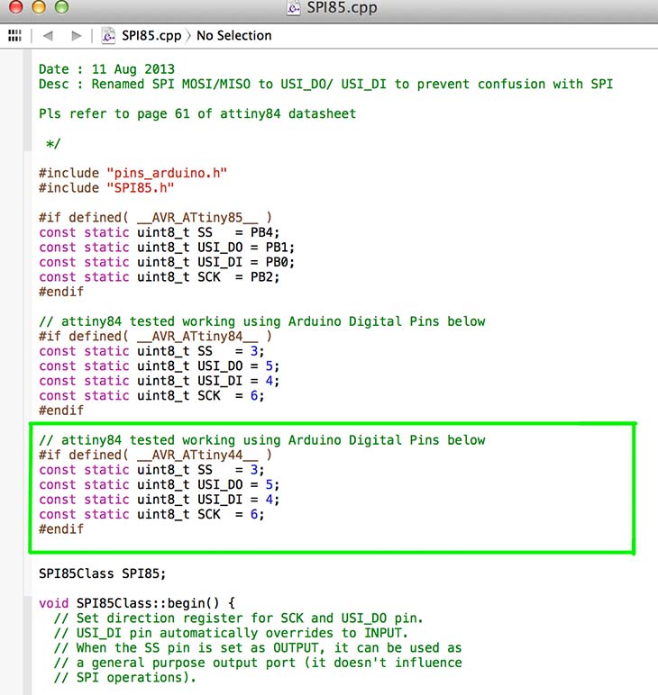
After installing all the right libraries it was time to program the board. I connected my transmitter board to my FabTinyStar and tried building the software. I got back some errors that some of the pins were not declared well. This was because in the SPI85.cpp the ATTINY44 was not declared. I changed this in the code and tried building again. It worked.
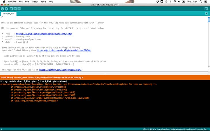
Now it was time to upload the example code to the board but unfortunately I got an error that the "Binary sketch size: 5,024 bytes (of a 4,096 byte maximum)" was too big. So I was stuck because it was already the minimum code needed for the project. I tried leaving out the debug code and it was able to write but the debug code is an important part to see if the board works. So I decided to order two ATTINY84s to replace the ATTINY44 with (I want to do this today). I forgot to make the fuses whic are very important! I did this through the Arduino IDE after installing the core packages. You can select the board and then burn the boot-loader on the board.
Assignment images:
Next steps:
- Make a board with the ATTINY 84
- Test the board
Update
After continuing to work on the two boards and programming I have been able to get the RF24 to work with the ATTINY84. I rearranged the pins in my design so they would follow the example code found here. I couldn't change certain pins because they where hard coded in the libraries so it was easier to switch some pins in the design.
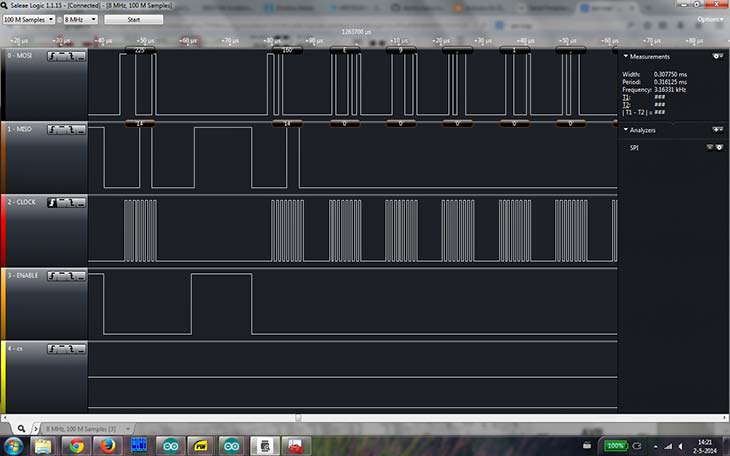
After creating the designs I soldered the components and used the code example to program the board with. The serial read was not working in my Arduino IDE and I didn't know why. I asked Dave to help me and he explained me the logic analyser so I could read out the pins on the FTDI Cable. It became clear to us we needed to switch around the MISO and MOSI and so we did by making a cable that would turn them around (we still do not know why we had to switch this around). After doing this, I was able to read out the correct data.
For the first test of the boards I used the ping_client and ping_server examples and edited it so they would work with the ATTINY84. This is something I already did for the mirf example, so this was quite easy. I just needed to set all the pins right and use the right libraries.
ping_client code
/*
 *  repo   : https://github.com/stanleyseow/arduino-nrf24l01/
 *  Author : Stanley Seow
 *  e-mail : stanleyseow@gmail.com
 *  date   : 8 Aug 2013
 *  Edited by : By Martin on 5 may 2014

 Some default values to take note when using this mirf/spi85 library
 Uses Mirf forked library from https://github.com/xdarklight/arduino-nrf24l01

 - node addressing is similar to RF24 libs but the bytes are flipped

   byte TADDR[] = {0xe3, 0xf0, 0xf0, 0xf0, 0xf0}; will matches receiver node of RF24 below
   const uint64_t pipes[2] = { 0x7365727631LL, 0xF0F0F0F0E3LL };

 The repo for the RF24 lib is at https://github.com/stanleyseow/RF24/
*/

#include <SPI85.h>
#include <Mirf.h>
#include <MirfHardwareSpi85Driver.h>
#include <nRF24L01.h>

// This USI was defined in SPI85.cpp
// Not to be confused with SPI (MOSI/MISO) used by ICSP pins
// Refer to page 61 of attiny84 datahseet
//
//#define USI-DO  5
//#define USI-DI  4
//#define USCK   6

#define CE    7
#define CSN   3

// ATMEL ATTINY84 / ARDUINO
//
//                           +-\/-+
//                     VCC  1|    |14  GND
//  SerialTx   (D  0)  PB0  2|    |13  AREF (D 10)
//             (D  1)  PB1  3|    |12  PA1  (D  9)
//  RESET              PB3  4|    |11  PA2  (D  8)
//  PWM  INT0  (D  2)  PB2  5|    |10  PA3  (D  7)  CE
//  SS/CSN     (D  3)  PA7  6|    |9   PA4  (D  6)  USCK
//  USI-DI     (D  4)  PA6  7|    |8   PA5  (D  5)  USI-DO
//                           +----+

int bufferSize = 0;
char buffer[32] = "";
unsigned int counter = 0;
uint8_t nodeID = 0;

void setup(){

  Serial.begin( 9600 );    // for tiny_debug_serial
  Mirf.cePin = CE;
  Mirf.csnPin = CSN;
  Mirf.spi = &MirfHardwareSpi85;
  Mirf.init();

  /*
   * Configure reciving address.
   */

  Mirf.setRADDR((byte *)"clie1");

  /*
   * Set the payload length to sizeof(unsigned long) the
   * return type of millis().
   *
   * NB: payload on client and server must be the same.
   */

  Mirf.payload = sizeof(unsigned long);

  /*
   * Write channel and payload config then power up reciver.
   */

  /*
   * To change channel:
   *
   * Mirf.channel = 10;
   *
   * NB: Make sure channel is legal in your area.
   */

  Mirf.config();

  Serial.println("Beginning ... ");
}

void loop(){
  unsigned long time = millis();

  Mirf.setTADDR((byte *)"serv1");

  Mirf.send((byte *)&time);

  while(Mirf.isSending()){
  }
  Serial.println("Finished sending");
  delay(10);
  while(!Mirf.dataReady()){
    //Serial.println("Waiting");
    if ( ( millis() - time ) > 1000 ) {
      Serial.println("Timeout on response from server!");
      return;
    }
  }

  Mirf.getData((byte *) &time);

  Serial.print("Ping: ");
  Serial.println((millis() - time));

  delay(1000);
}
ping_server code
/*
 *  repo   : https://github.com/stanleyseow/arduino-nrf24l01/
 *  Author : Stanley Seow
 *  e-mail : stanleyseow@gmail.com
 *  date   : 8 Aug 2013
 *  Edited by : By Martin on 5 may 2014

 Some default values to take note when using this mirf/spi85 library
 Uses Mirf forked library from https://github.com/xdarklight/arduino-nrf24l01

 - node addressing is similar to RF24 libs but the bytes are flipped

   byte TADDR[] = {0xe3, 0xf0, 0xf0, 0xf0, 0xf0}; will matches receiver node of RF24 below
   const uint64_t pipes[2] = { 0x7365727631LL, 0xF0F0F0F0E3LL };

 The repo for the RF24 lib is at https://github.com/stanleyseow/RF24/
*/

#include <SPI85.h>
#include <Mirf.h>
#include <MirfHardwareSpi85Driver.h>
#include <nRF24L01.h>

// This USI was defined in SPI85.cpp
// Not to be confused with SPI (MOSI/MISO) used by ICSP pins
// Refer to page 61 of attiny84 datahseet
//
//#define USI-DO  5
//#define USI-DI  4
//#define USCK   6

#define CE    7
#define CSN   3

// ATMEL ATTINY84 / ARDUINO
//
//                           +-\/-+
//                     VCC  1|    |14  GND
//  SerialTx   (D  0)  PB0  2|    |13  AREF (D 10)
//             (D  1)  PB1  3|    |12  PA1  (D  9)
//  RESET              PB3  4|    |11  PA2  (D  8)
//  PWM  INT0  (D  2)  PB2  5|    |10  PA3  (D  7)  CE
//  SS/CSN     (D  3)  PA7  6|    |9   PA4  (D  6)  USCK
//  USI-DI     (D  4)  PA6  7|    |8   PA5  (D  5)  USI-DO
//                           +----+
int ledPinRed = 10;
int ledPinGreen = 8;
int ledPinBlue = 1;

int bufferSize = 0;
char buffer[32] = "";
unsigned int counter = 0;
uint8_t nodeID = 0;

void setup(){

  Serial.begin( 9600 );    // for tiny_debug_serial

  Mirf.cePin = CE;
  Mirf.csnPin = CSN;
  Mirf.spi = &MirfHardwareSpi85;
  Mirf.init();

  pinMode(ledPinRed, OUTPUT);
  pinMode(ledPinGreen, OUTPUT);
  pinMode(ledPinBlue, OUTPUT);

  Mirf.setRADDR((byte *)"serv1");

  /*
   * Set the payload length to sizeof(unsigned long) the
   * return type of millis().
   *
   * NB: payload on client and server must be the same.
   */

  Mirf.payload = sizeof(unsigned long);

  /*
   * Write channel and payload config then power up reciver.
   */

  Mirf.config();

  digitalWrite(ledPinRed, HIGH);
  digitalWrite(ledPinBlue, HIGH);
  digitalWrite(ledPinGreen, HIGH);

  Serial.println("Listening...");
}

void loop(){
  /*
   * A buffer to store the data.
   */

  byte data[Mirf.payload];

  /*
   * If a packet has been recived.
   *
   * isSending also restores listening mode when it
   * transitions from true to false.
   */

  if(!Mirf.isSending() && Mirf.dataReady()){
    Serial.println("Got packet");

    /*
     * Get load the packet into the buffer.
     */

    Mirf.getData(data);
     if (data[0] == '1') {
      digitalWrite(ledPinRed, LOW);
      digitalWrite(ledPinBlue, HIGH);
      digitalWrite(ledPinGreen, HIGH);
     }
     else if (data[0] == '2') {
      digitalWrite(ledPinRed, LOW);
      digitalWrite(ledPinBlue, LOW);
      digitalWrite(ledPinGreen, HIGH);
     }
     else {
      digitalWrite(ledPinRed, LOW);
      digitalWrite(ledPinBlue, LOW);
      digitalWrite(ledPinGreen, LOW);
     }
    /*
     * Set the send address.
     */


    Mirf.setTADDR((byte *)"clie1");

    /*
     * Send the data back to the client.
     */

    Mirf.send(data);

    /*
     * Wait untill sending has finished
     *
     * NB: isSending returns the chip to receving after returning true.
     */

    Serial.println("Reply sent.");
  }
}
Conclusion:
You really have to think everything through. I still feel with every step there is a possible bump you walk into. Overall, it's really a great learning process and it's just trial and error.
Conclusion v2:
There are still some mistakes that I made in creating the circuit board (connection wise). It is really important to check your board before you start milling it. I had a mistake where I put the GND instead of the VCC on the 4 pins LED connector for my RGB breakout board.
Next steps:
- Make the serial.read work so I can send different light patterns to the server.
- Redesign the boards double sided