Electronics design
The assignment of the week was to design your own electric board,
which will have a LED and a button to turn it on.
In this assignment I used two softwares:
Eagle, free download software to determin the place of the components

Adobe Illustrator, to design the shape of the board

I never used the eagle software before so I decided to use
a very good tutorial made by Anna from 2013:
eagle-electronics design
I worked with the tutorial and the eagle step by step and was able to understand the logic
behind the connection of the components with one another.
**one thing which was missing in the tutorial.
I had some problems with naming the legs of the microcontroller in the eagle software.
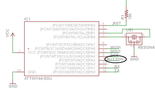
in order to add the name- BUTTON and LED to the legs of the microcontroller,
you should first drew the green line which comes under the name.
than press on the 10th and 6th leg to name the leg. after naming the legs,
you can't see the name. in order to see the name you should press show in the toll bar
and than press label. than you will see it in the schematic.
in order to copy the name, double click on the name and drag it to where you want to place it.
after adding the right components to my file in the eagle, it was time to design them
in a way which looked the most practical and aesthetical way:
The most important thing for me in the components design part was to put the button
outside of the circuit so it would be comfortable to press on.
after I finished this part of the design I checked that my electric circuit can work
by clicking the ERC button in the Tool bar:
after seeing that my design can work I had to save the file as a PNG file.
*** very important to remember is to close all the layers besides the "top" layer before saving as PNG:
if you don't close the other layers the modella will mill the name of the components as well.
after I closed the layers I recieved this file:
than saved it as PNG:
after I saved it as PNG I recieved this file:
now I could go with this file to Illustrator and design the shape of my board.
also important to know is that it is better to add text in a graphic design software rather than in eagle.
becuase the board is rather small I wanted to design a board which will be comfortable for
the fingers to hold the board. I created two designs:


**above are the interior files for the milling machine.
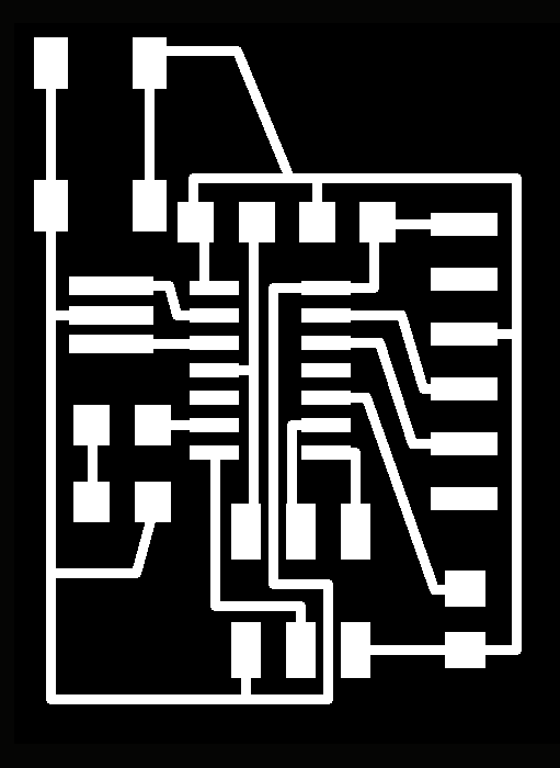
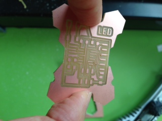
here is the traces file for the milling machine:
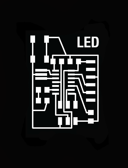
after I designed the shape of my board and added the text in illustrator
I started to mill it in modella:
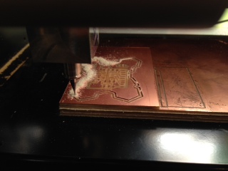
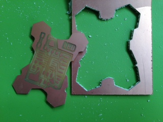
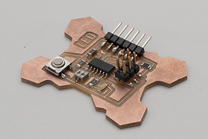
I was able to create a good grip place for the fingers.
However, becuase of the shape I wasted a lot from the material,
so it is not the most economical board.
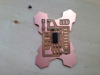
after I finished to mill the board it was time to solder the components.
.jpg)
***after I programmed this PCB I realized there is a shortage,
becuase the button does not have a resistor between it and the VCC,
the LED works but without the button!***