I designed and built the final projects in many stages. My goal was to produce many functional prototypes to test and evaluate the concept. Moreover I wanted break down the development into different parts according to the employed technology.
An initial plan was to work separately on:
- electronic design (sketching and CAD), prototyping on breadboard and production
- software development in MAX and in Arduino
- 3D/2D design (sketching and CAD), prototyping with cheap materials (paper, foam)
- fabrication, use of the CNC and the laser cutter
- assembly, mounting and testing
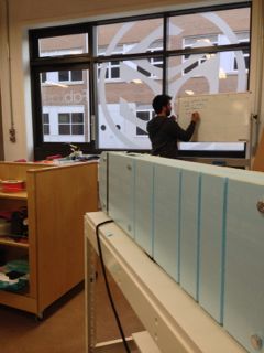
An overview of the working space (Fab Lab Cardiff) can be found on the following video.
It was necessary to make a very simple prototype for the proof of concept. I used cardboard, breadboard and an Arduino board for the electronics and a very simple MAX patch to check the instrumentation.
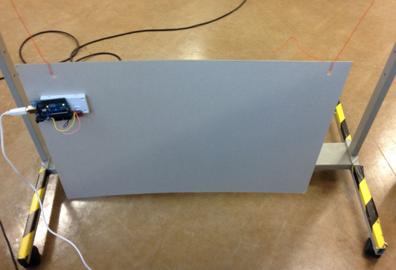
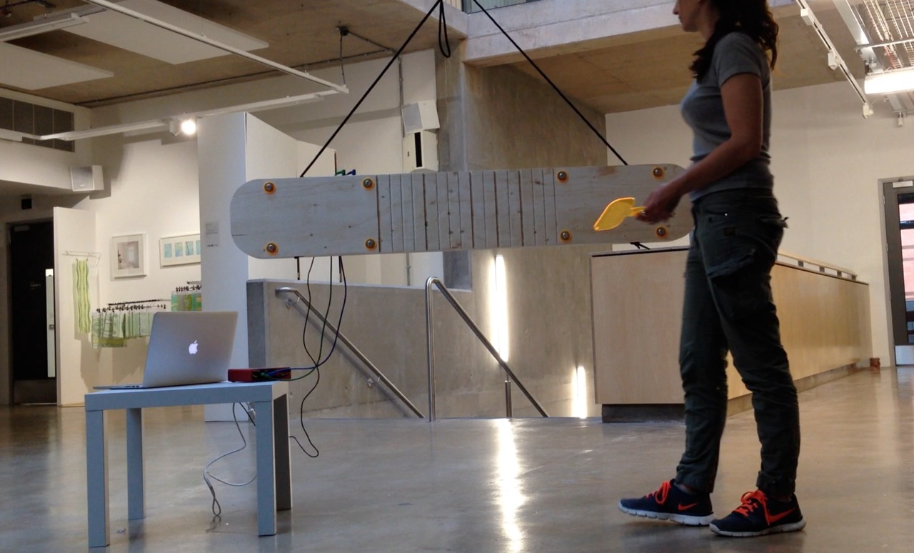
The following video demonstrates that the basic interaction works: the visitors of the exhibition can interact with the installation by striking it with a mallet, rubbing it and pushing the piece of wood and make it swing in two directions.
The piezoelectric sensors have been tested with an oscilloscope
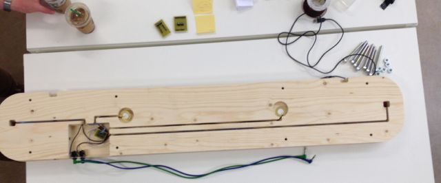
In order to calculate accurately the dimensions and produce clear design I have drawn in one-to-one scale the Talando with the electronics inside it.

The following foam prototype was machined by the CNC milling machine. The designs were developed in Rhino.
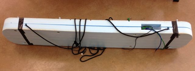
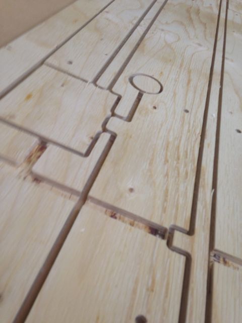
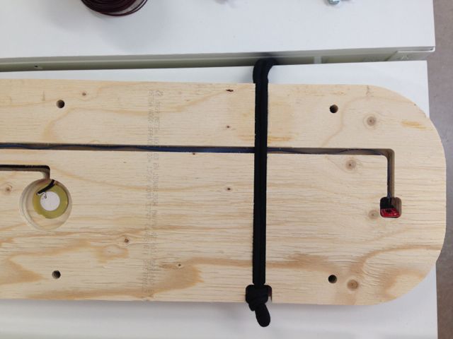
The tracks for the wires, the sensors, the board and the rope are visible here:
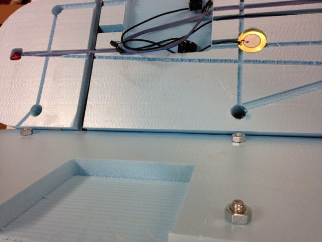
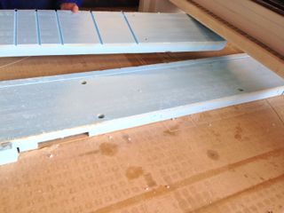
Foam secured with lots of double sided tape, milled on one side and flipped on the other side [3rd image below] . Used excess foam I used only one toolpath for the prototype and one tool [6mm spiral]. Almost everything went right. What went wrong [tip for next time]: There is a Z parameter, that controls the height of the tool once it moves from one set of coordinates to the other to mill at another part of the drawing. This one was set lower than the highest Z of the drawing. What happenned is that the tool carved its movement into the material. Luckily it was the foam prototype.. This can be shown at the picture above, showing the cuts at the interior part of the board.


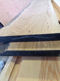
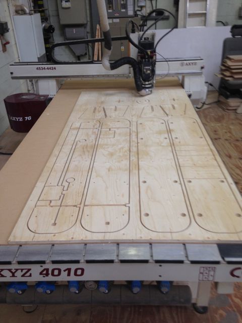
The design was made having in mind the material being the American White Oak which is of 35mm thickness [total of 700mm]. However the one I have used at the end due to financial restrictions as price exceeded £100/ €130, is four 18mm plywood sheets put together to make a 720mm thick end object.
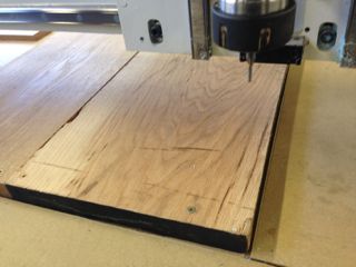
In fact it was so close for the Oak Talando to be built. Here are the photos I took when setting up the machine , just before I found out about the Final project cost restrictions:
Anyway, the design had to be re-tweaked for the 4 part- ply.
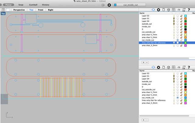
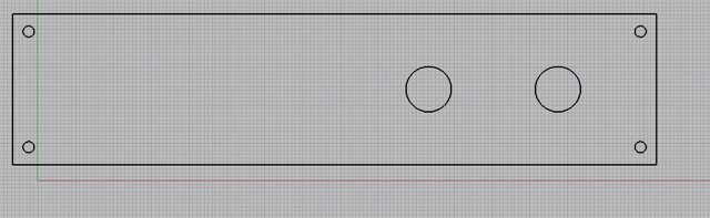

Below are the dxf files that were sent to Artcam that is used by the large AXYZ cnc. The top two parts are the inner parts where all the electronics will be housed. The bottom two parts are the exterior ones with the very bottom one having the talando pulse/ traditional rhythm carved on it.

A few photos of the final piece:


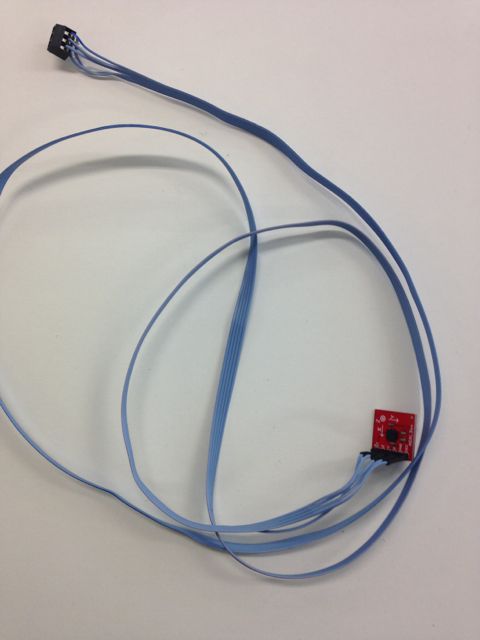
I order to attach the the accelerometers to fabduino board, I have developed a shield
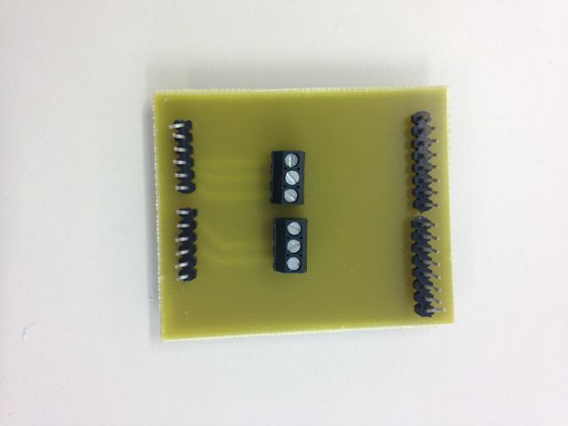

In my initial idea I wanted to use two accelerometers. When I started making low-cost prototypes like the one with the cardboard, I found out that it was not essential. In the final implementation of the project I have finally used only one accelerometer. However, I have made two accelerometers and on mechanical design I have previewed to use both.
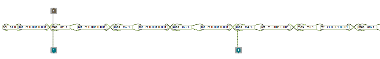
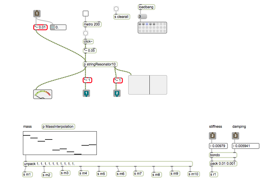
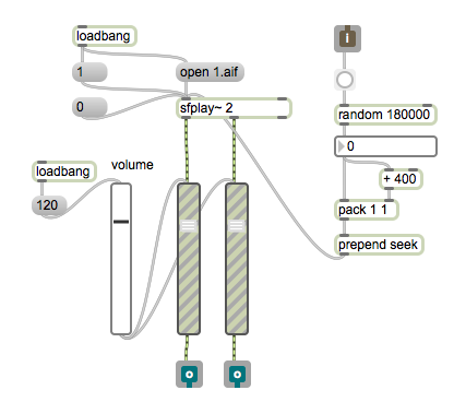
I have developed the software application in MAX visual programming language. The sound engine of the application consists of a resonator based on a string physical model (mass-interaction physical modeling paradigm). I want to design a physical model in order to establish a dialog and a contrast between the physical and the virtual. The physical model is based on a version of an open source physical modeling library I have developed with a colleague in the past
The graphical user interface is simple and informative. It gives information about the piezo senors activity and the acceleration on two axis
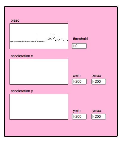
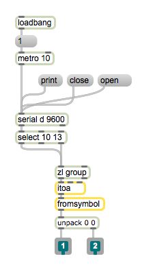
The application has three components: the communication with the electronic board, the aui

The string can be tuned homogeneously or may have overtones that don't follow the harmonic series.
I have used a audio player similar to the one I developed for my Application Interface Programming assignment.
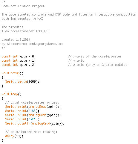
The fabduino board (with the shield) was programmed on Arduino. It uses the serial port (through the FTDI cable) to communicate withe the application
The Eagle files for the schematic, the board and the developed library can be found below.
schematic , board and library part.
The following video demonstrates briefly the interaction. The Talando is stroke by a laser cut mallet. The sound is generated by the vibration of the wood and by the physical model. The vibrations are captured by the piezoelectric and through the audio interface excite the resonator model. The sound envelop is also used to trigger samples randomly. The acceleration is mapped to model parameters (stiffness and damping).
The drawings can be found
here[talando design].
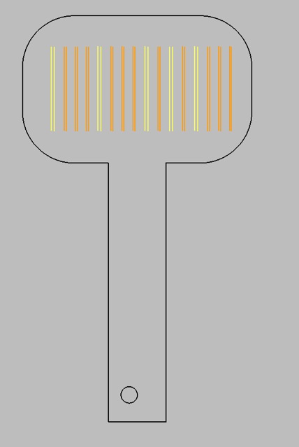
here[mallet design].
here[talando design].
here[talando design].