Johannes Fischer
I want to learn "How to make (almost) anything"!
That's why I take part in the Fabacademy 2014.
I want to learn "How to make (almost) anything"!
That's why I take part in the Fabacademy 2014.
This is what I have done for Assignment 1. For me it is very convenient to have just a single page where everything is included. This keeps all the information in one place and allows very simple updates (just one single file). Thanks to the nice template, the website looks quite impressive, too!
Our task this week was to play a little bit with many different CAD tools and to model the final project.
Download sources of this weeks assignment
Inkscape
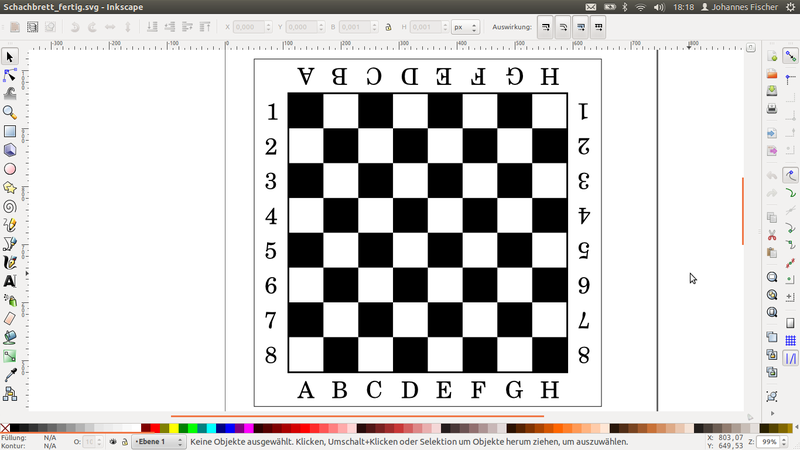
First of all I wanted to learn Inkscape and I designed a chess board with it. I was impressed that you can draw very precise with Inkscape and it has many helpful things build in like grouping objects and rotating/mirroring. In the toolbar there are boxes where you can enter numerical values for the position or the size of the object, what I found very helpful.
SketchUp
After that I carried on with 3D-CAD-Tools. I played a bit with SketchUp and I was very impressed how easy 3D-modelling can be! I think SketchUp is a very good starting point for everybody intersted in designing 3D objects.
DesignSpark Mechanical
I had my project already designed in OpenSCAD, thats why I wanted to try some other CAD-Tools I ever wanted to learn. DesignSpark Mechanical from RS-Components was suggested to me and so I started using it. Since I was used to scripting 3D-objects in OpenSCAD, it was quite difficult to get used to having a fancy GUI and buttons. But I figured out quite soon that it is very powerful, especially if you want to change something after you have finished your design. By grouping objects logically that belong together, you are able to simulate the behaviour of your machine, for example by clicking and dragging the x-carriage.
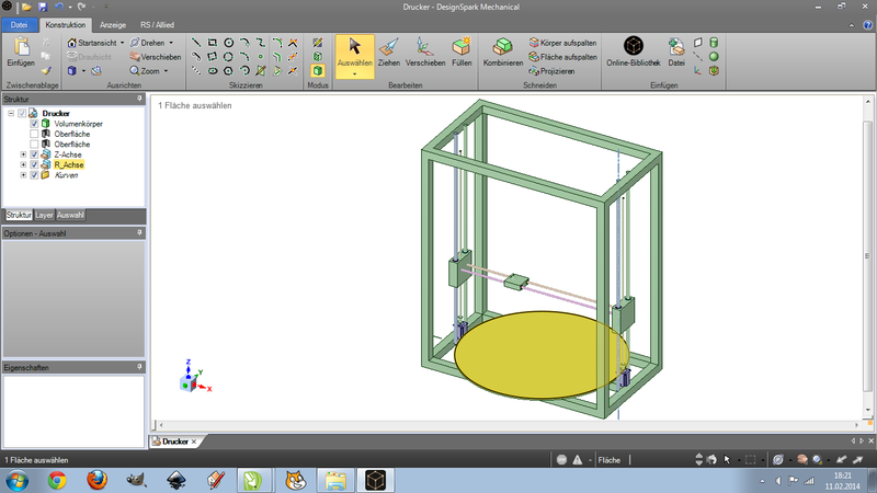
DesignSpark is very powerfull because it has a large online component database by RS-Components. Unfortunately not every part of their product range is available as a 3D-design and I found only a hand full of mechanical components in the database at the moment. Sadly I found no components I could use in my design, but I believe that it is the perfect tool for designing housings for electric circuits and the like.
Inspired by the idea that you can get designs for "of the shelf"-components online I looked at all the companies where I buy these parts and found out that all of them have 3D-Designs of their parts available for free! That was a great insight for me, because I can design the whole machine in more detail much easier without having to measure and draw every part myself. I was impressed by the huge amount of available file interchange formats. For me "iges" and "step" worked very well, but the step files I got had the advantage that more objects in one import-file could be grabbed separately.
OpenSCAD Animation
I had my final project already designed in OpenSCAD. So I thought it might be a good idea to simulate some movements in OpenSCAD. To achieve this I used the variable $t, that goes from 0 to 1 during the animation. All the movements are now done by incrementing $t. After adapting the source a little bit I was able to enable the animation mode in "view->animate". I entered 2 for the FPS and 12 for the steps to reduce the size of the animation. After activating "dump pictures" all the images of every step get saved to the same folder with names like "frame00000.png".
Afterwards I created an animated gif out of all the single images by using imagemagick. A simple "convert -delay 50 -loop 0 frame000* animation.gif" did the task for me!
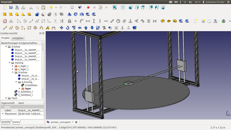
FreeCAD
Afterwards I wanted to have the ability to use my component library in open source CAD tools. For this reason I tried to use FreeCAD, which seemed very promising. The learning curve is quite steep, but it does seem to be very powerful. Compared to DesignSpark, it has some shortcomings and some benefits. But I am sure it will do a great job for me!
Our task this week was to try computer aided cutting with a vinyl cutter and a laser cutter and to design a press-fit construction kit.
Download sources of this weeks assignment
Playing with the Vinyl-Cutter
I started using the vinylcutter with the device-driver from the vendor. I figured out quite soon that the cutting software only works with vector grapics and that eps can also embed raster images!
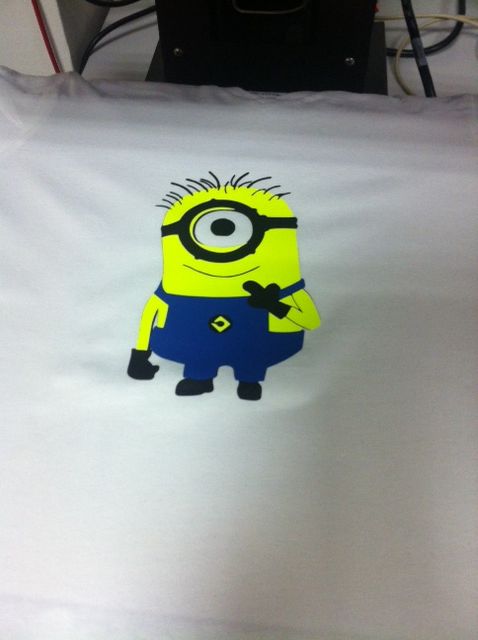
I wanted to make a T-Shirt with objects in multiple colors. It turned out that the results are not very precise (i guess this is due to scaling), so the single pieces did not fit perfectly. But the tolerances are in a very small range, so the result looks quite nice.


Afterwards I wanted to use the fab modules for vinyl cutting. Thanks to the great instructions on the mailing list by Sherry and Jean-Baptiste, I was able to set up everything properly. The fab modules are very nice and powerful. It turns out they are much easier to use than I had expected (on ubuntu)! You simply plug in your device, go to the printer settings, enter your password to become root, add the new found device as a "Generic Model" as brand and "Raw Queue". What is very important here is the name of the device, so if you want to use a vinyl cutter you have to enter "vinyl" as name.
Working with the Silhouette Cameo was a bit tricky, as it needs some modification of the generated .camm file. First of all you have replace all the PU (PenUp) commands with M, and all the PD (PenDown) with D, otherwise all the movements are also cut. Furthermore the start sequence has to be changed from (something similar to this):
to
Afterwards you can send the modified .camm file to the printer with the fab_send tool. But be careful, because the "print" is twice as large as it should be.
What I like a lot about the fab modules, but what might be a bit confusing in the beginning, is that every single task has its own command. So for example if you want to vinyl cut something from a pixel image, you have to use the command make_png_camm, if you want to make the same file on an epilog laser cutter you use the command make_png_epi. Thanks to the nice modular framework implementing your own features is quite simple. For example, I wanted to vinyl cut a half-tone image from a png, so I adopted the code to create a command for half-tone vinyl cutting .
Designing a Press-Fit Construction-Kit for the Laser Cutter
I was working with a dual layer cardboard that is about 6.6 mm thick. In the first step I wanted to come up with good settings for cutting and graving the cardboard. I started with small values and incremented them in small steps until I had good results. Afterwards I wanted to find the right cutout-width for the joints, again by varying the size in small steps.
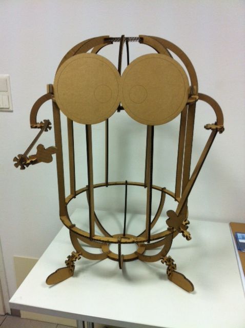
Afterwards I started designing the construction-kit. I wanted to build a minion figure where the body is fixed (two press-fit joints meet each other) and the other parts (eyes, hands, feet) can be attached in any position (one press-fit joint meets plain cardboard).
The Body
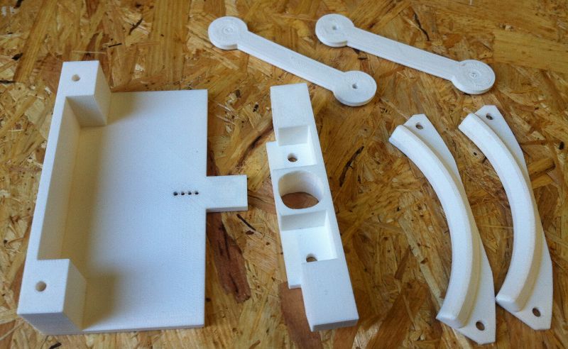
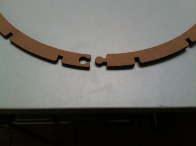
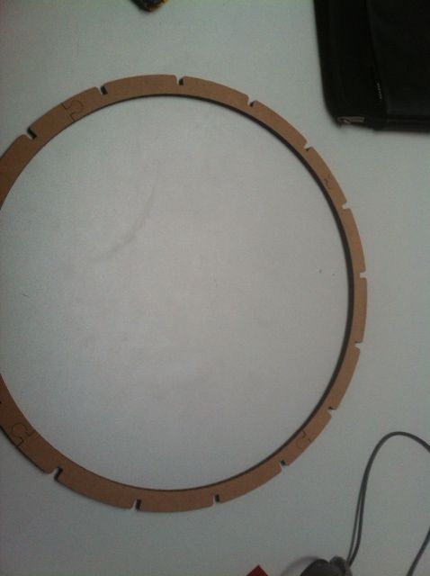
The body consists of small top and bottom rings, two larger center rings, 8 connecting straights and 16 connecting bows.
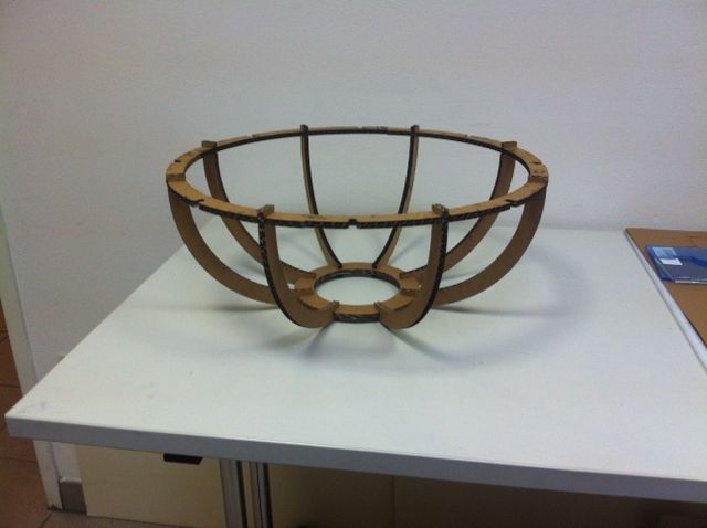
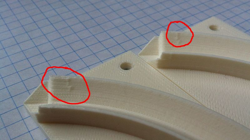
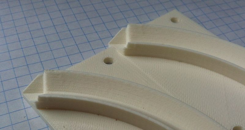
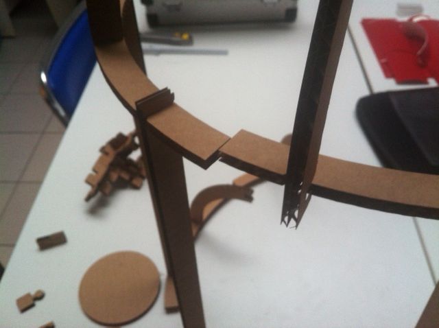
I wanted the body to be as big as possible but use as little material as possible. For this reason I have split the big ring into four identical sections, 90 degrees each. The problem with this setup was that these sections had no joints and so the stability was very poor. But I remembered the connectors of my toy wooden railway and after added these connectors the stability issues were solved.
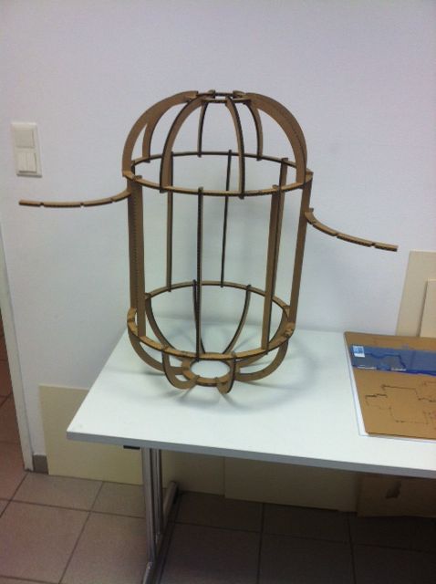
The other Parts
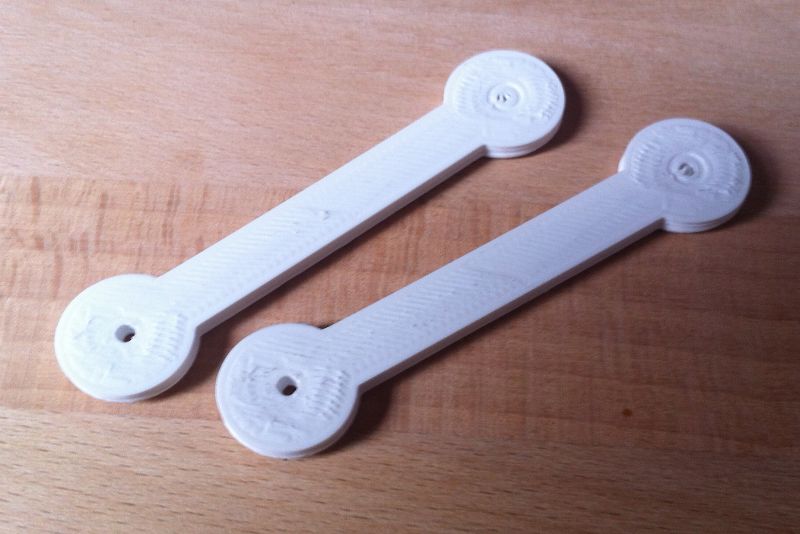
All the other components should be attached and detached quite easily. For this reason I designed a bunch of universal connectors in different sizes and with an step of eighter 45 degrees and 60 degrees. The glasses, arms or feet can be connected to the body with these connectors and a bunch of different connecting rods.
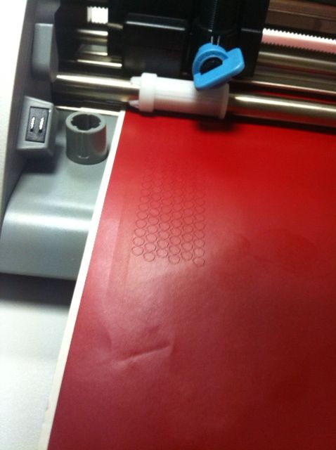
Playing with flexible structures
I was very impressed by the images of the flexible laser cut structures. For this reason I wanted to play a little bit with this technique. I found a test pattern on the internet that I wanted to test on the cardboard. Unfortunately the design was for plywood so the cuts were a little bit too close and the cardboard went on fire! So I scaled the pattern a bit larger, and I could cut a flexible cardboard. Sadly the result was not too impressive, so I tried another pattern on plywood, and that worked quite well. But the result was not as impressive as I had expected it, so for achieving better results you should take the right wood and better settings for the spacing.
Our task this week was to make the FabISP, a small In System Programmer for AVR Microcontrollers. As it turns out, my friend Murphy and his law was working aginst me this week ;-) !!!
Milling the PCB
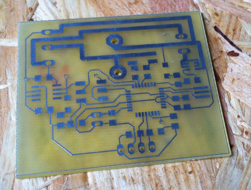
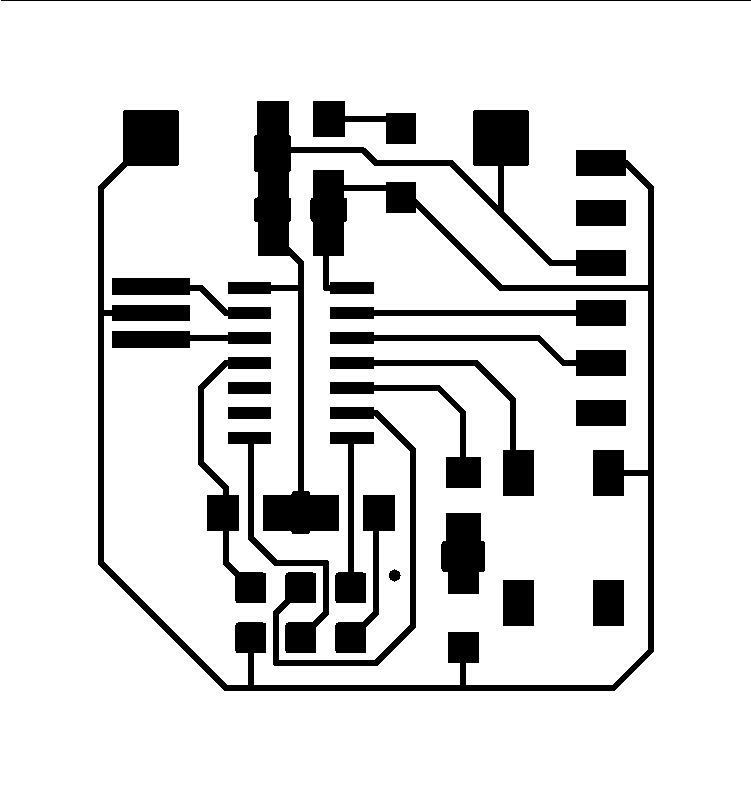
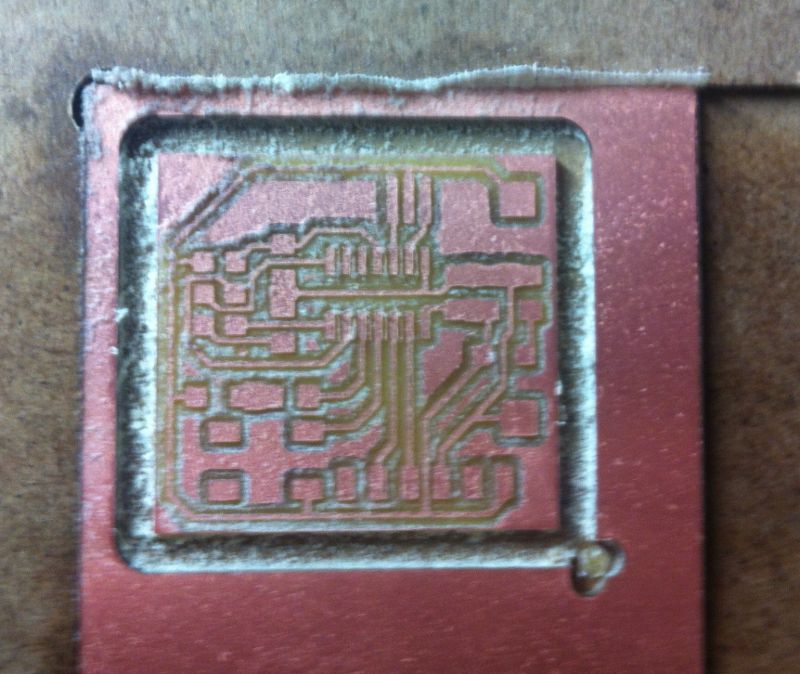
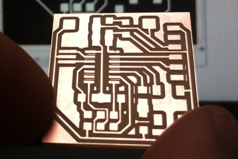
Milling the PCB was not so easy for me, as we only had a 0.5mm tool head here and the design needed a 0.4mm tool head. I was cheating a bit, telling the fab modules I was using a 0.4mm tool but using a 0.5mm tool for milling afterwards. The result is that all my pads and connections are now a little bit too small. Because of that, some of the connections lifted off the board and were cut during the milling process. But with a little bit of repairing the PCB was usable.
I was milling my board on a different CNC than suggested by Neil. For this reason I was using the make_png_g to generate the G-Code for our machine. After some small adaptions I was able to use that code for milling the PCB. But I had to increase the spindle speed to the maximum (24 000 rpm), otherwise I broke the tool head instantly.
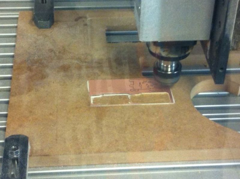
My setup for milling the PCB
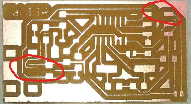
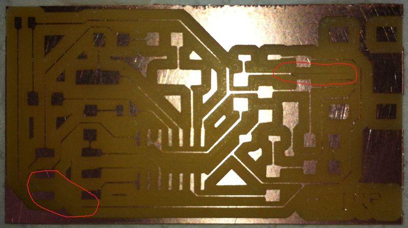
Some connections are missing (marked in red)
Soldering the PCB
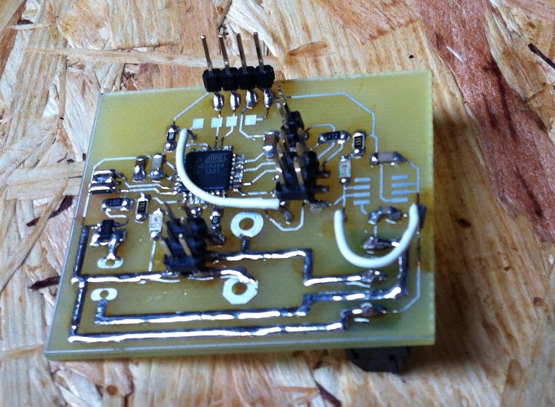
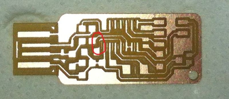
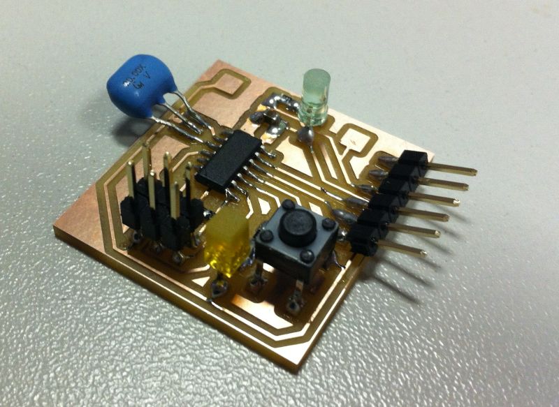
Soldering the PCB was also not so easy for me because I had to repair the PCB and we just had 0805 components around, but the PCB is designed for 1206 component size. It turns out that it is possible to use the smaller parts in this layout, and also bridges worked well (maybe due to the smaller sizes after milling ;-).
For repairing the disconnected parts of the PCB I was using some special insulated wire, that can be uninsulated with the heat of the soldering iron. This was very helpful for this task!
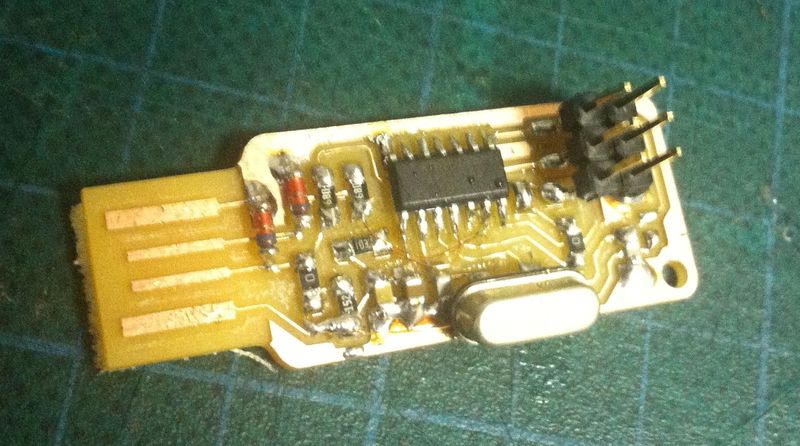
The finished FabISP
Programming the FabISP
I was using a Atmel AVRISP MKII to program the board, that we have in our lab. After adapting the Make-file (different programmer and different quarz) everything should have worked out of box. As it turned out, that was not the case. I did not solder the jumper for the voltage supply but I was not aware that the AVRISP MKII was measuring the voltage of the target board (my other programmer doesn't have this feature, either). The error message you get from avrdude is not very helpful for debugging. But with the help of our electronics-expert (thanks a lot for that) and the Atmel AVR-Studio (that was indicating this problem almost instantly) I was finally able to program the programmer (after closing the jumper for voltage supply).
Testing the FabISP
After connecting the FabISP to the computer it registers as:
I am using the 10 pin connector specified for AVR ISPs in my other designs and development boards. So I had to build a small adapter cable that converts the 6 pin to the 10 pin layout. After that I was able to connect to my development board without any issues.
Hint for using avrdude without sudo in Ubuntu
If you get some messages like the ones below using avrdude, there is a small trick other than using "sudo avrdude":
Generally it is not a good idea using standard programs with sudo (security issues)!! So the workaround is to just create a new file at "/etc/udev/rules.d/80-usbprog.rules" and enter the following content to it:
After disconnecting your programmer and reconnecting it again avrdude should work fine without sudo.
Our task this week was to design something that can only be produced by 3D-Printing. Moreover we had to perform 3D-Scans on real-life objects.
Download sources of this weeks assignment
3D-Printing
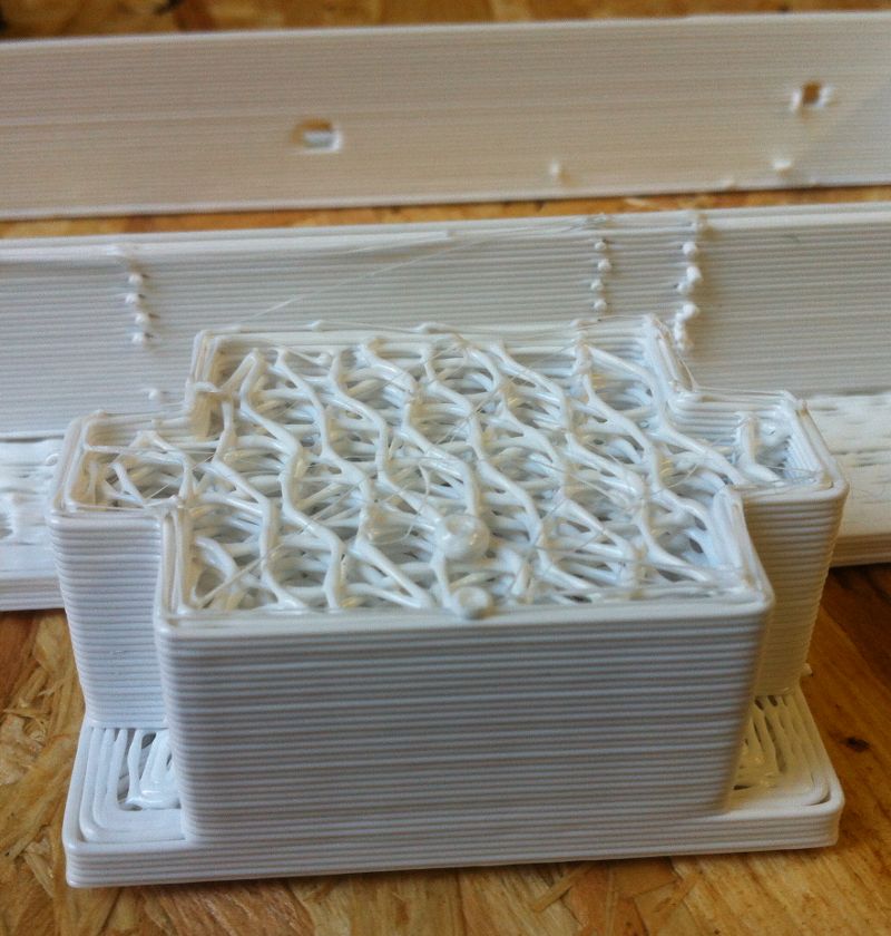
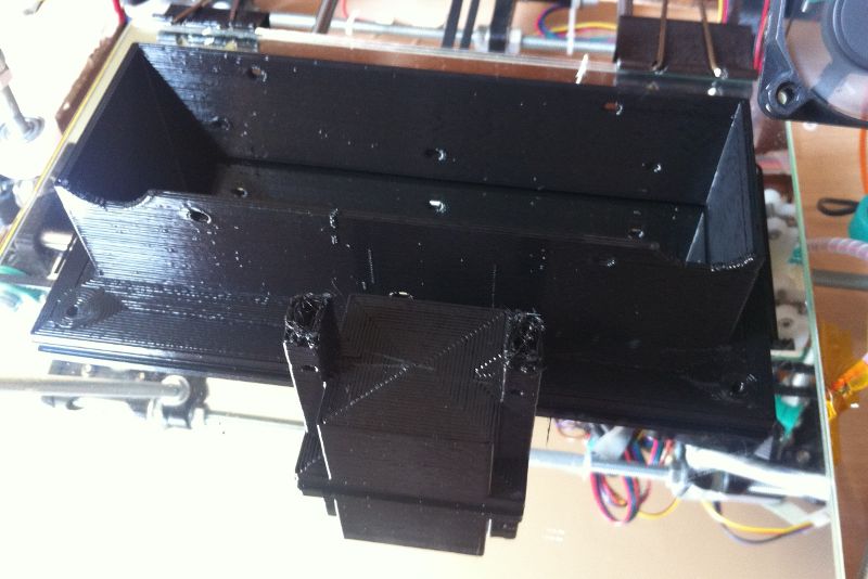
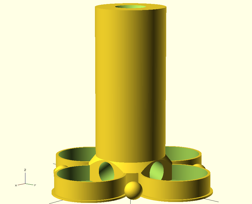
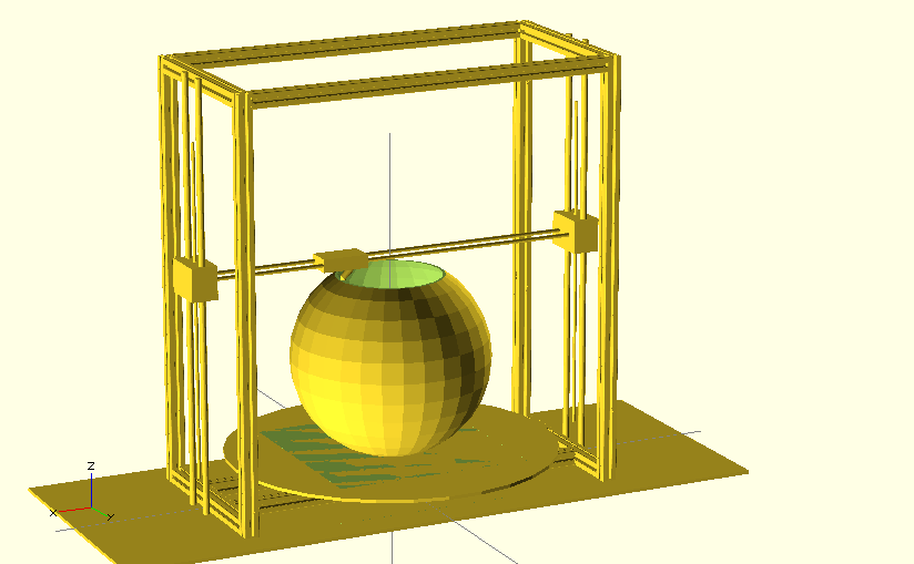
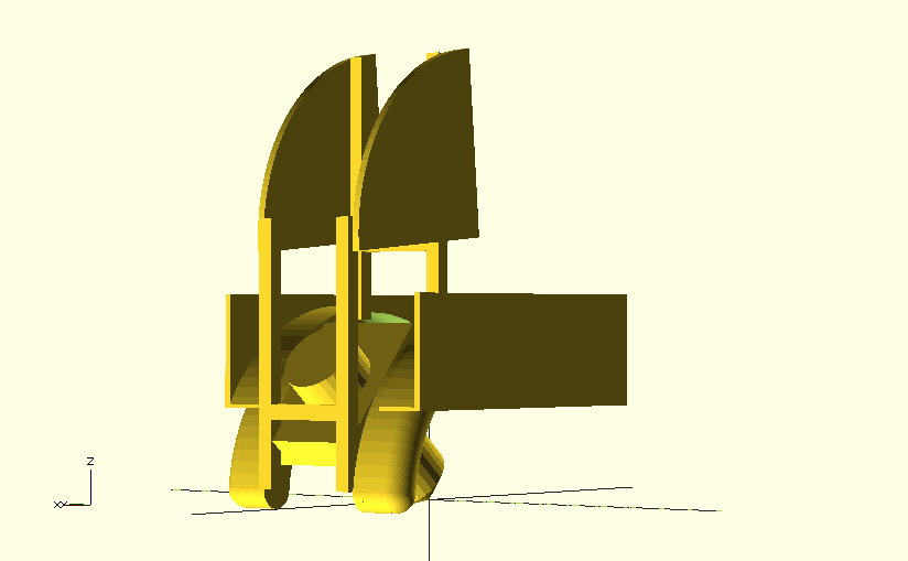
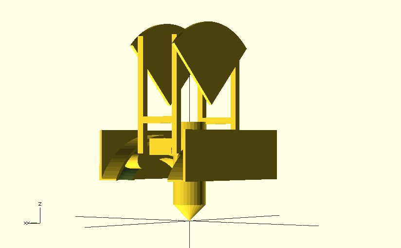
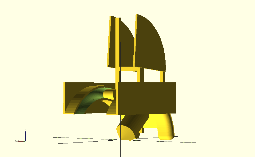
This week I wanted to create a physical random generator. The idea was to have an object with one hole in the top where you can insert a small ball and four possible outlets, where the ball might be released again.
The main parts, where the randomness is generated are a helix, where the ball is spinned around the center axis of the object, a funnel afterwards, where the ball is guided to the center again, and four outlets at the and of the funnel with boxes to catch the ball.
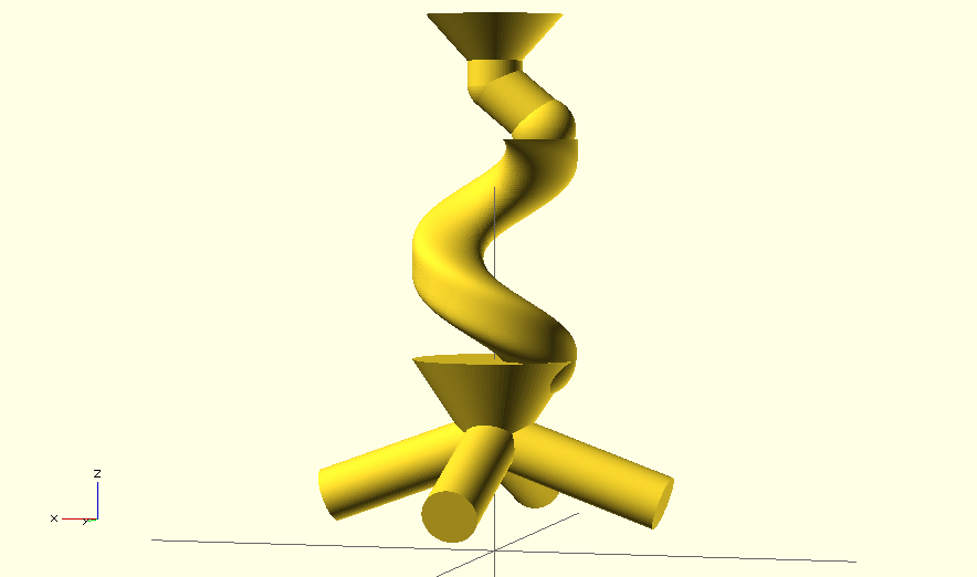
All those parts where embedded in a small tower, and the final object looks like that:
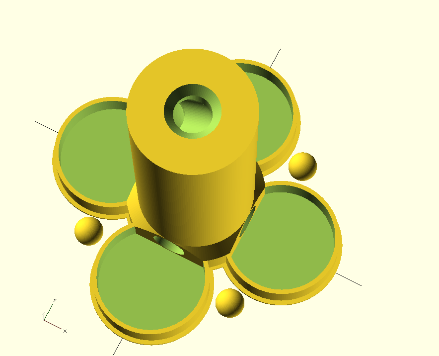
Printing the object worked right out of the box, and thanks to the soluable support material the result is perfect:
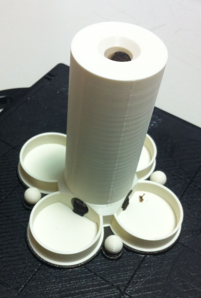
Thanks to the fact that the 3D-printed balls are not symmetric in the inside (because of the infill), the random generator works really good (as long as the floor is perfectly horizontal ;-)!
3D-Scanning
After the perfect printing result I wanted to get similar scanning results. As it turns out, there is not one 3D scanning process that is suitable for all objects.
Photogrammetry
First of all I wanted to go BIG. I already did some 3D-Scans with photogrammetry, mostly faces, and the results were quite good. But this time I wanted to go much bigger. I wanted to do 3D scans of some historic sights in vienna!
I have to admit that I had some great step-by-step tutorials on How To do photogrammetry properly and How To install VisualSFM in Ubuntu and How To improve point clouds in MeshLab, that helped me a lot during the process. But once you figured out the critical parts, the process is damn simple. Just take a bunch of pictures all around the object you want to scan, hand them to the 3D-photogrammetry software and let it generate the object from that images.
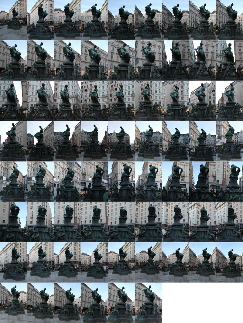
All the pictures for the scan.
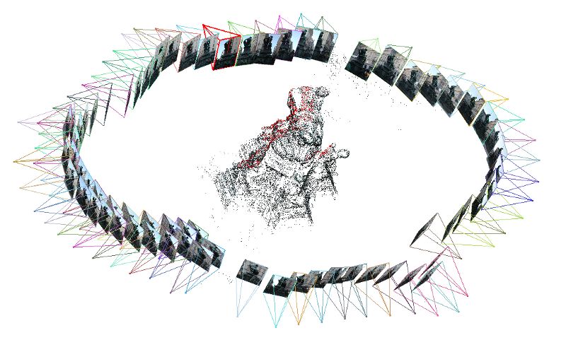
All the pictures arranged around a sparse point cloud.
If all the images are aligned correct, the software generates a dense point cloud of the object.
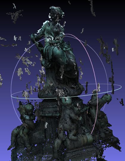
The generated dense point cloud.
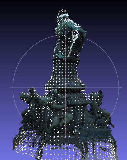
The reconstructed surface after cleaning the point cloud.
Here are some more impressions of other objects:
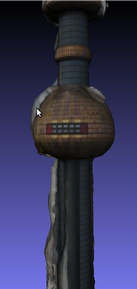
A huge tower on my way to the lab (large holes in the scan cause this artifact)!
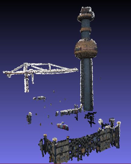
The same tower but the uncleand pointcloud of the scene before remeshing!
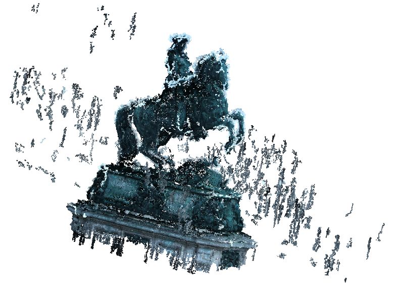
A horse statue, scanned in very dark environment.
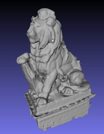
A sculpture of a lion (not reconstructed in best quality)!

Stephansdom in vienna, scanned with about 180 Pics, a bit too much for my hardware (so just lo resolution, no reconstruction of the point cloud).
As you can see clearly, some objects are harder to scan with this process than others. Moreover the quality of the source images is very important. I would suggest to take your pictures during a cloudy, bright day (gives very even light from all directions). I was impressed that the scan of the dome worked that well (I expected it to be much worse!). It turns out that taking multiple images from one point does not disturb the process, as long as you keep on moving around the hole object as well. Taking the pictures from the sky would be a great advantage here ;-)!
I remember someone has asked about 3D scanning from a video. I remember I did something like that a few weeks ago. My setup looked like that:
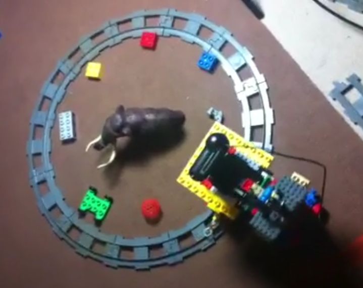
We mounted a USB webcam onto a LEGO train, lit the scene as well as we could and grabbed a video while the train was circling around the object. The setup would need a bit more tweaking (more light, better cam for sharper images, ...), but the result shows that the more pictures you have the better the results are.
The pictures where extracted from the video with ffmpeg, and afterwards used for the same processing pipeline as explained above. The command for ffmpeg is:
Where i specifies the movie, r is for the frame rate (how much pics per second you want to extract) and the last name stands for the file names of the generated images.
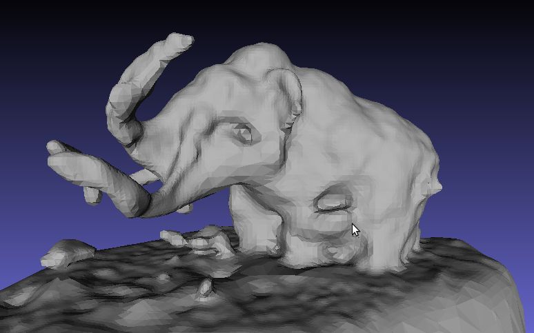
Resulting 3D-Scan of the Train-Scanner.
DAVID Laserscanner
Afterwards I wanted to try the famous DAVID Laserscanner. Sadly I was not able to get good quality scans with the line laser due to a much thick line of the line laser and too much ambient light around the scene. The DAVID Laserscanner is said to produce quite decent results, but the setup is very critical!
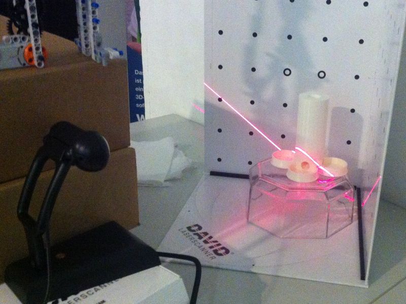
Scanning with a line laser (Note the reversed order: I was scanning the printed part ;-)!
DAVID Laserscanner - Structured Light
I did not care about those bad results as the new versions of DAVID also have a Structured Light Scanning mode, that looked very promising to me. After I figured out how to setup everything (the best way is to place the camera in front of the calibration panel and the beamer above the camera) the scanning worked very well. Fast (a few seconds for one side), textured scans, some postprocessing included and a shape fusion algorithm that lets you combine all the single shots to one scan (did not test that as the free demo does not allow export from that). If I need scanning, I will build a turntable and some setup with the david.
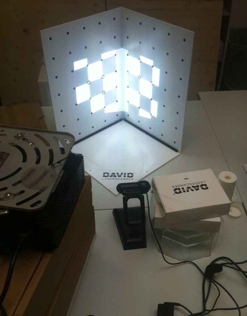
Scanning with structured light (Note: the beamer is projecting the checkerboard pattern on the calibration planes !!!! ;-)!
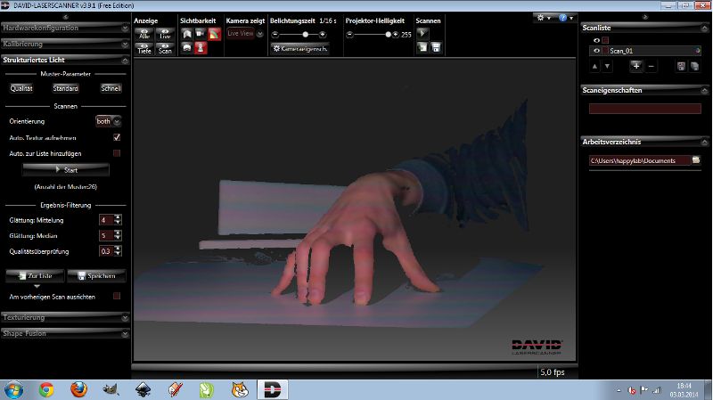
Scanning result of a my hand with the DAVID SLS

Scanning result of my face, exported in low quality due to the limitations of the free version.
Our task this week was to design the "hello-FTDI"-Board and to make it.
Download sources of this weeks assignment
Designing the board
After I got used to eagle, designing the board was quite straight-forward. Just a few small hints for the next time: Do make sure to set up the raster properly in the board-window (units in mm, show the grid and 0.635mm raster, alt-raster to half size), the alt raster is enabled by hitting the "alt"-key and pads can be drawn as polygons with the same name as the electrical connection they extend. Also don't worry about the export of the image too much, as the diameters (or the dpi) are stored in the png-image itself, just make sure only the right layers are visible when exporting the image.
Many thanks at this point to everybody who helped me dealing with eagle, especially to Christoph.
Milling the board
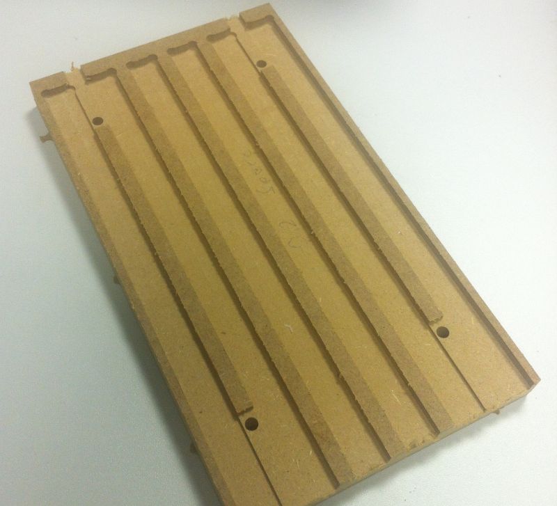
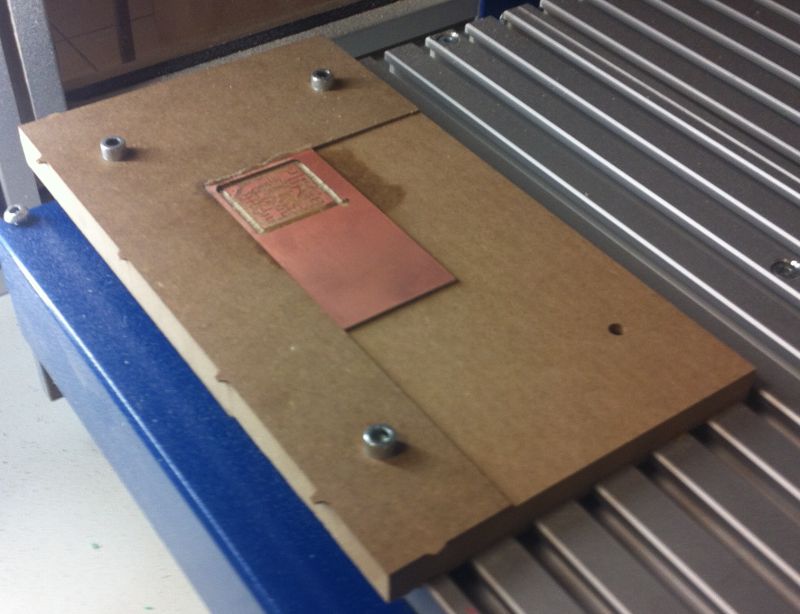
Milling the circuit board was straight forward this time. Partly because I had a 0.4 tool head this time and partly because I had built my own sacrificial plate out of MDF, that makes the process now super simple! Many thanks to Roland (one of the founders of the happylab) for this great idea, now milling PCBs is great fun.
Soldering the board
The only problem this week was that all the ordered components did not arrive in time! Fortunately the lab has a lot of TTH components, that I placed onto the SMD-pins. Everything is working fine, but the board looks a bit weired now ;-)!
Testing the board
After checking the boards for shorts and checking all the connections I wanted to test the board if it is working properly. For this reason I wrote a small test program (NOTE: I connected the LED to PA3 and the switch to PA2)
Our task this week was to make something big out of wood on a CNC.
Download sources of this weeks assignment
Design
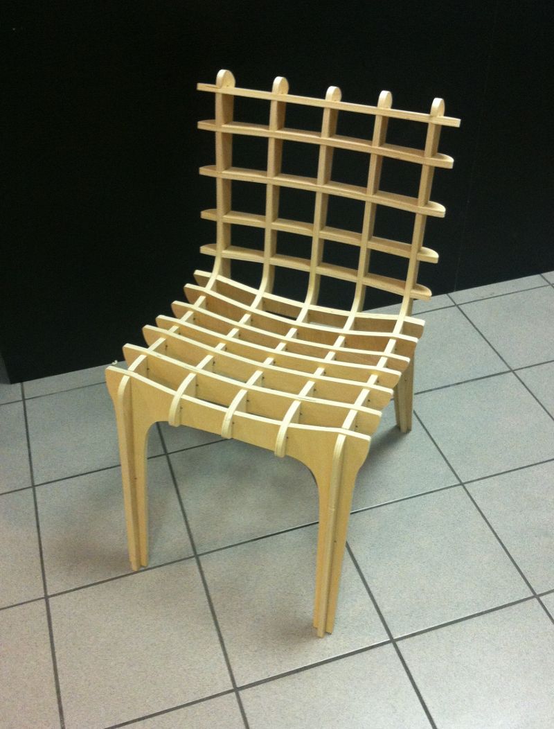
Karim, one of the founders of the happylab, found a nice software to create chairs called sketchchair. Although the software is a bit unstable, the idea behind it is great! So I gave it a try.
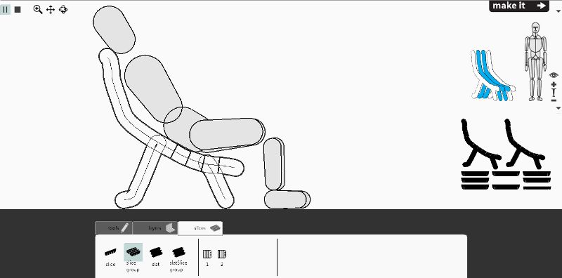
It is quite simple to use and has a kinematic test to try the chair before you make it:
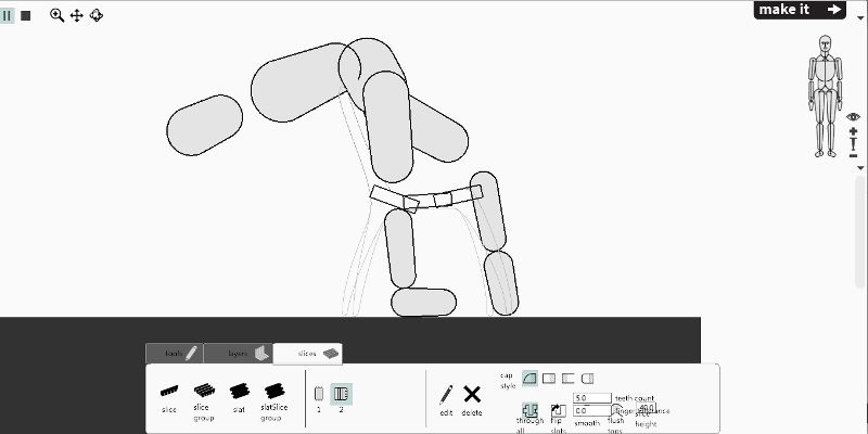
I did not know that I am that flexible ;-)!
Make
Unfortunately the export did not work well for me, so I went online and got one of the available designs. But this was also not very sucessful (as I found out in the first test), because the svg-file seems to be buggy and gets scaled when you want to convert it to a dxf. Moreover some paths were not closed (and could not be milled therefore), but there is an option in Cut2D to close open paths.
Anyway, after rescaling the file and reorganizing everything on my sheet of wood and fixing all the other issues I was able to mill my chair.
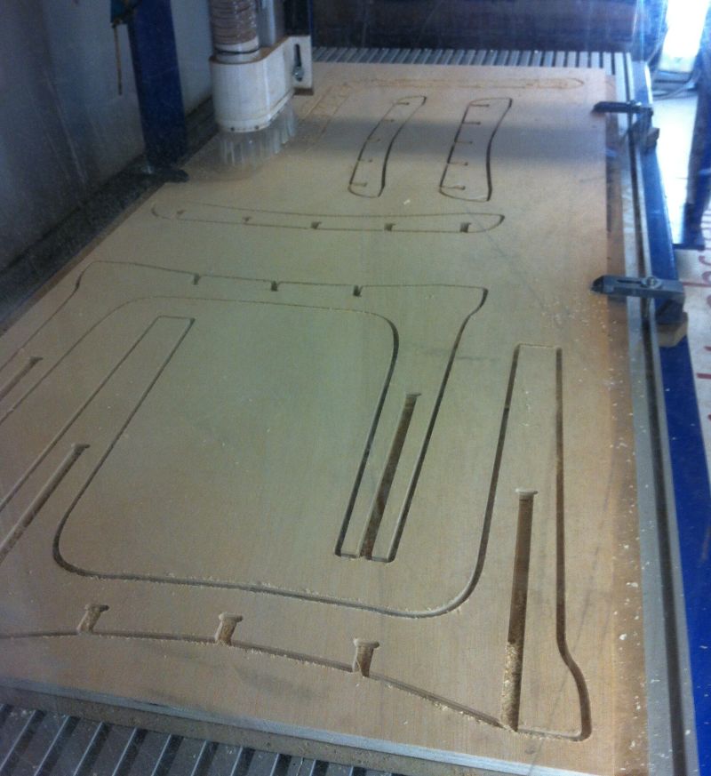
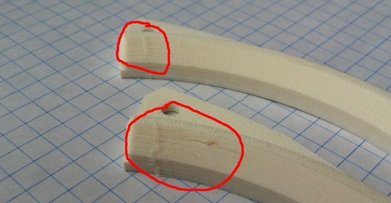
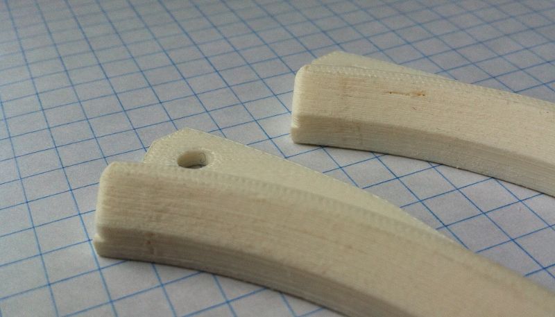
Milling everything lasted about two hours, afterwards I started assembling.
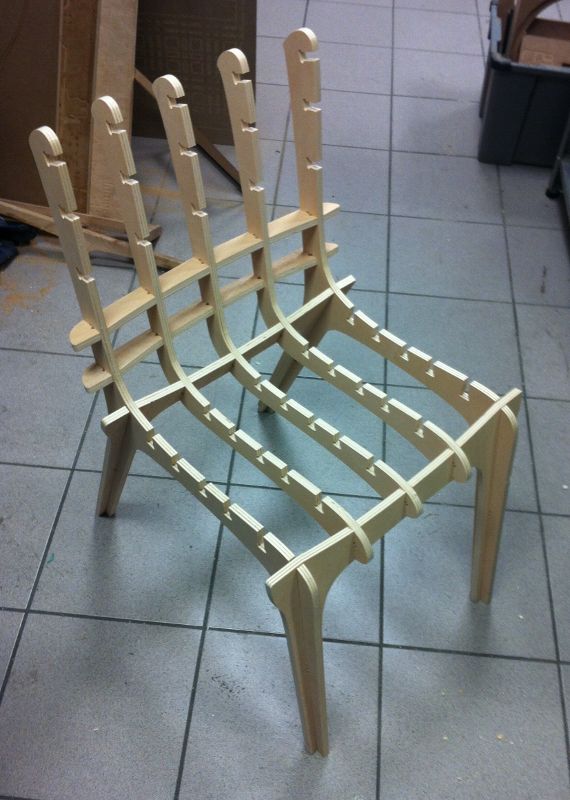
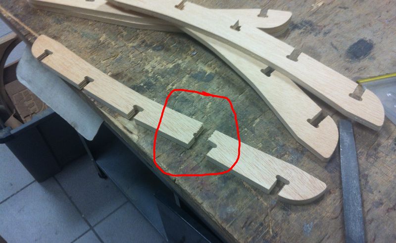
Unfortunately one of the pieces broke while assembling the chair. I had some material left so I milled a replacement part.
And here is how the final result looks like:
Our task this week was to try as many different programming languages and programming environments as possible.
Download sources of this weeks assignment
AVR for children
I have already used AVRs for some projects and as a computer scientist I know how to code in C and environments like Eclipse. But I always wanted to have a very easy to understand graphical user interface for simple microcontroller programming. Because Neil mentioned Scratch in his lecture, I wanted to have a similar tool for AVRs that is suitable for children. So I asked in the lecture and the answers I got were amazing:
Our task this week was to design a mold, mill it on the CNC machine and cast a part in that mold.
Download sources of this weeks assignment
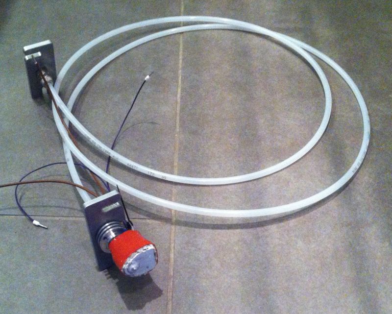
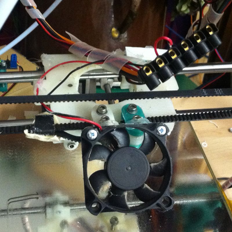
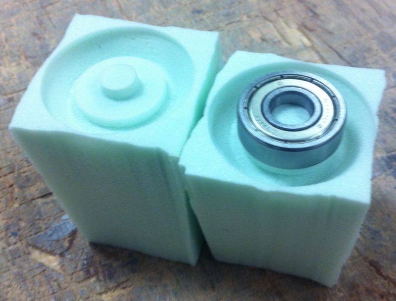
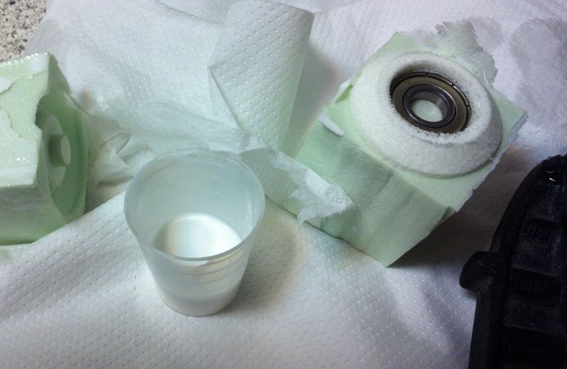
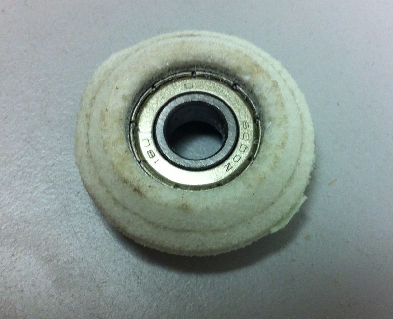
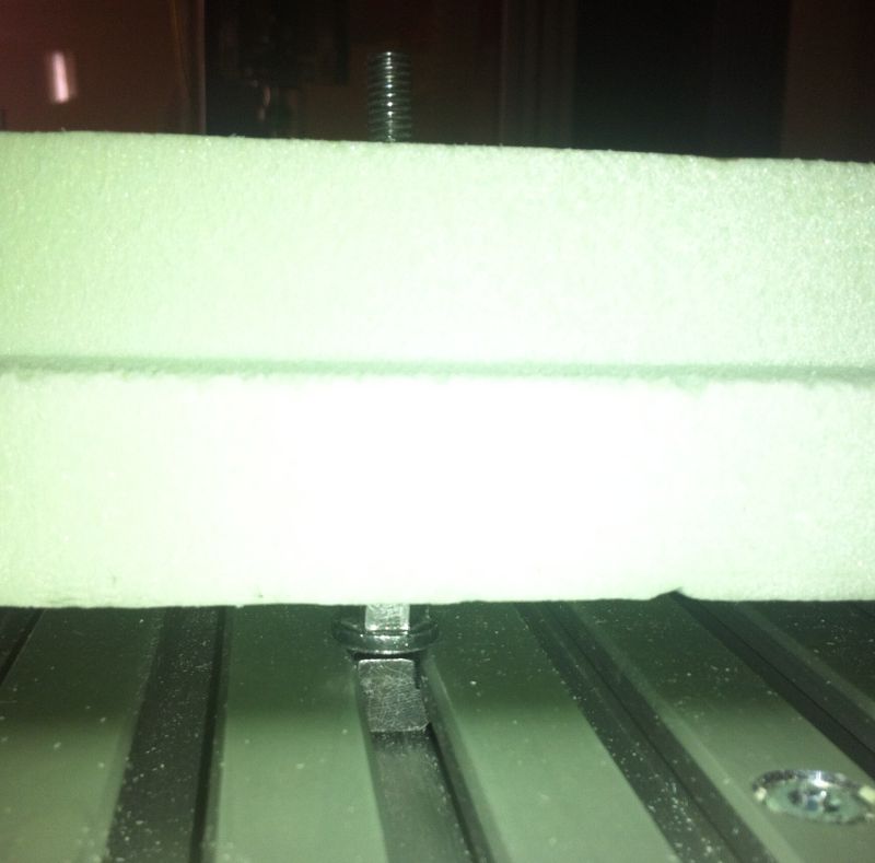
I liked the idea of casting bushings, but we did not have the right material for this task in the lab. So I decided to make a v-shaped roller bearing that can slide on a t-slot aluminium extrusion instead.
Designing the mold
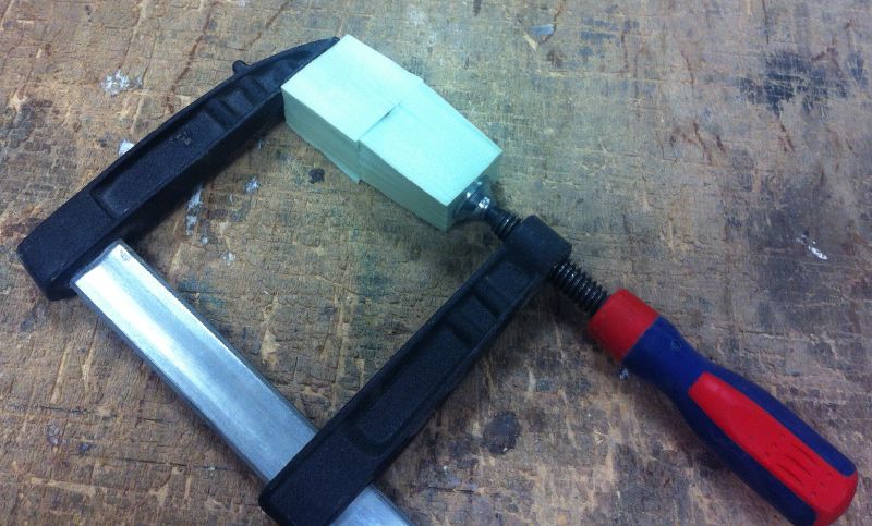
I wanted to cast an off-the-shelf roller bearing inside the liquid plastic. So I designed a two sided mold that holds the bearing in place while casting the part.
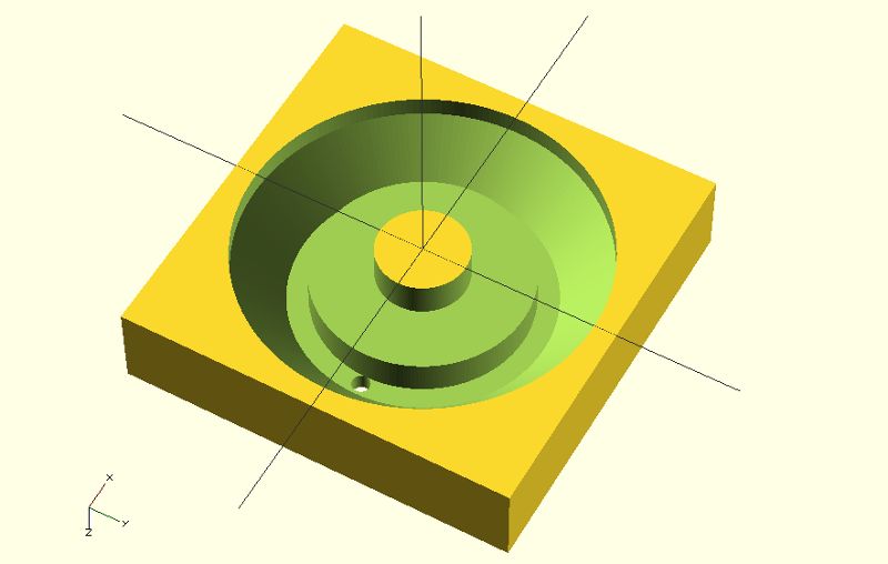
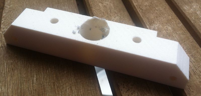
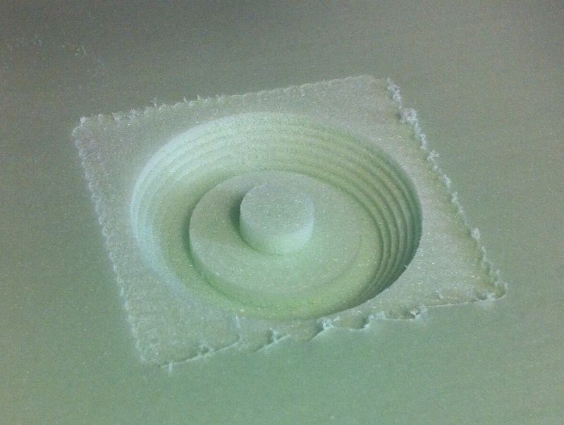
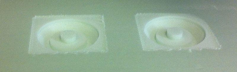
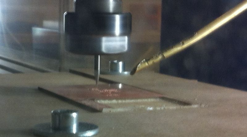
Milling the mold
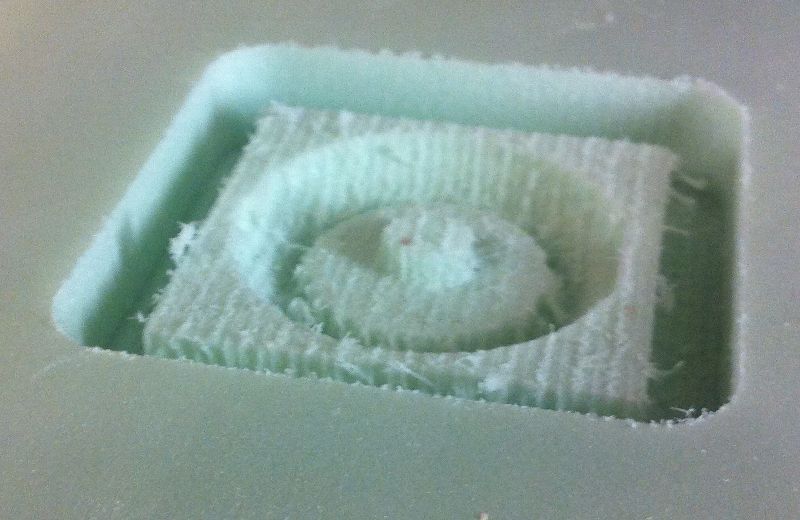
I took some foam to make the mold. As it turned out milling the mold was a bit tricky. First of all I tried milling the mold with Cut3D, but the result was quite rough.
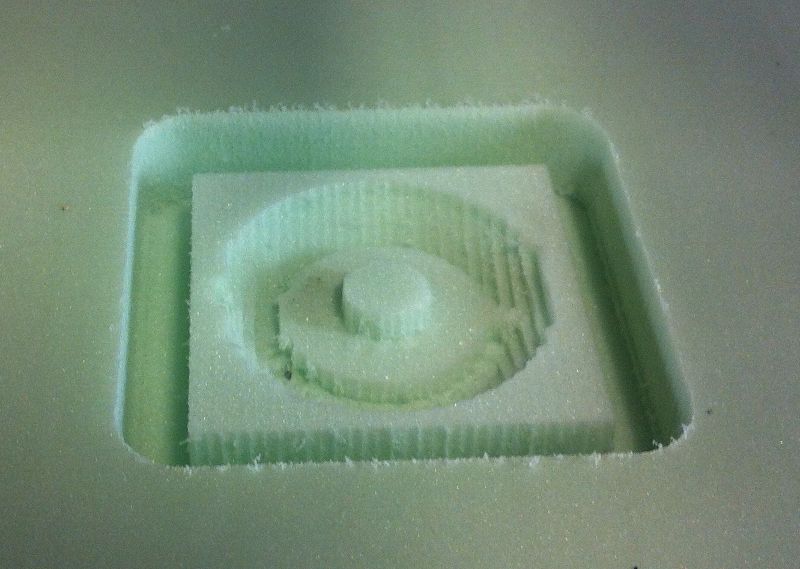
Taking a ball-end mill instead of the flat endmill did not make the result much better.
Our task this week was to design a new AVR-Board with an input device and make it.
Download sources of this weeks assignment
Motivation
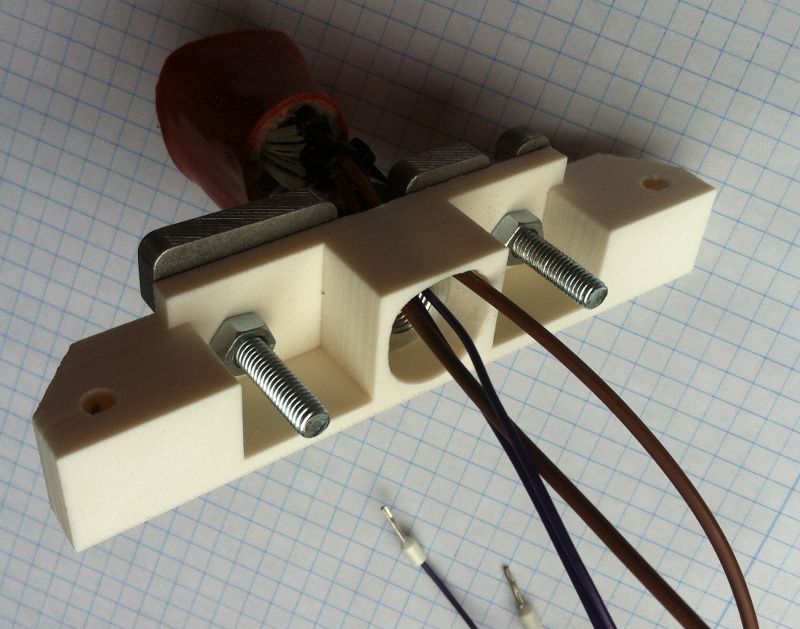
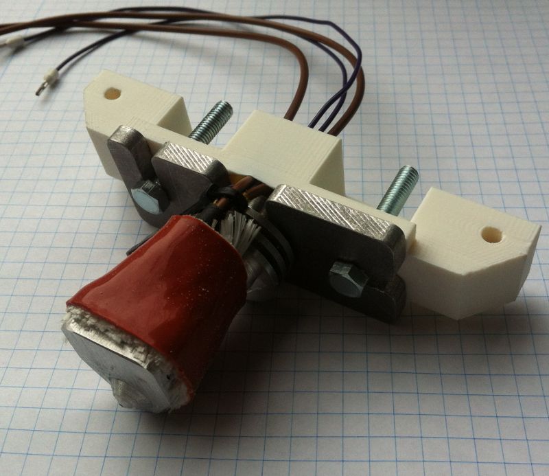
I was fascinated by the hall sensor this week. I read in the reprap forums that you can make very precise endstops with the help of a hall sensor. In the proposed design they are using a potentiometer and a comparator to convert the analog signal of the hall sensor into a digital signal of an endstop. I wanted to do that in software to have more capabilities (e.g. removing the hysteresis of the hall sensor) and have less components with temperature drift.
Design the board
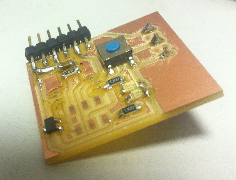
So I started designing a small test board that is capable of both, sending the measured data to the PC (for the development process) and acting as a real endstop. I added a pushbutton to set the triggering level for the endstop and an LED to show the status.
Make the board
As I am quite confident now with the process of milling PCBs I wanted to experiment a little bit with a different tool. Here in our lab there are two guys who are milling their circuit boards with engraving bits and their results are very good (although they use a slightly different workflow).
In a first test I took a slightly too large engraving bit so my traces were really thin. Nevertheless the resulting board is working fine. The next I am pretty sure I will get the same results as with the 0.4mm endmill, but with slightly lower costs and (hopefully) a longer lifetime of the bit.
Programming the board
I started with the "hello world" code from Neil to get used to the behaviour of the hall effect sensor. Then I added the code that triggers the output whenever a specific value is reached (remember: it should act as a switch). I added some code to store the triggering-value of the sensor into the EEPROM so that it is preserved during power off. Unfortunately I needed a new makefile that was capable of both, compiling the source code and the content of the EEPROM. I found a good makefile at a great german microcontroller website that I adepted for my purpose. On the same website I also found a great tutorial to access the EEPROM .
Destroying the board
I was always looking for a good solution to get rid of the large ISP headers on small PCBs. So I tried to just press the ISP header onto the pads for the header while programming the chip. This worked surprisingly well for a while. But unfortunately I went off the pads once and fried the attiny. So I had to desolder the microcontroller with our IR-lamp. This worked quite well, but some of the traces lifted off from the PCB (due to the different milling bit). But after soldering the new chip (and the ISP header this time ;-) the board worked well again.
So my solution is to use the soldered ISP header for the development board and try the clip for ICs the next time for smaller boards or small series.
Findings
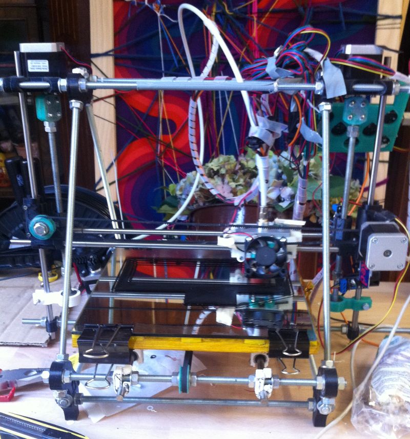
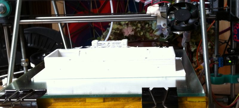
The board works very nice as a configurable endstop-switch! Whenever a magnet gets close to the sensor, the output is triggered (indicated by the LED). I have to test if the precision is better than the micro switches and the optical endstops by mounting the system onto my printer.
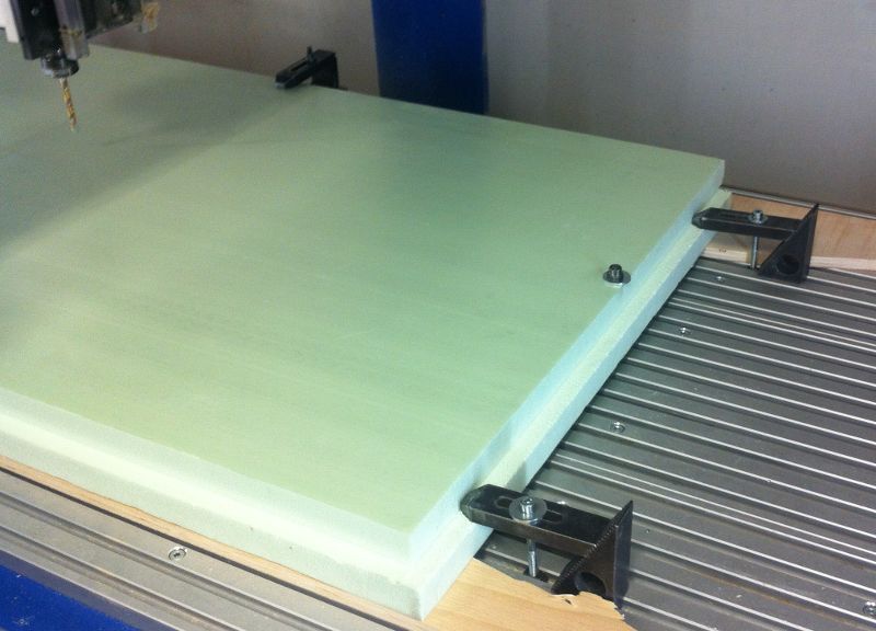
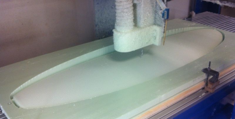
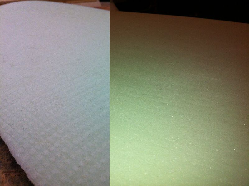
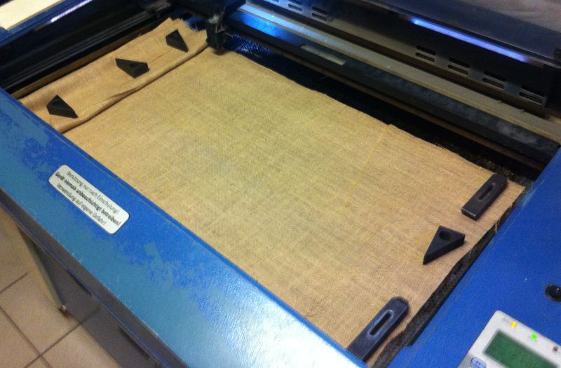
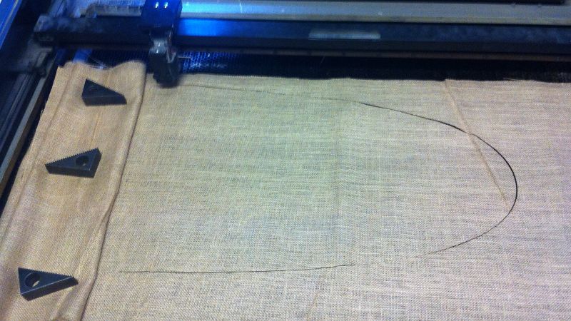
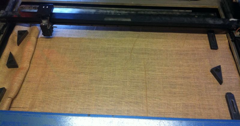
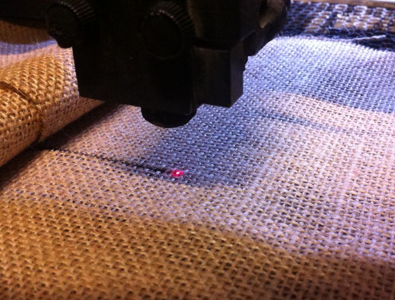
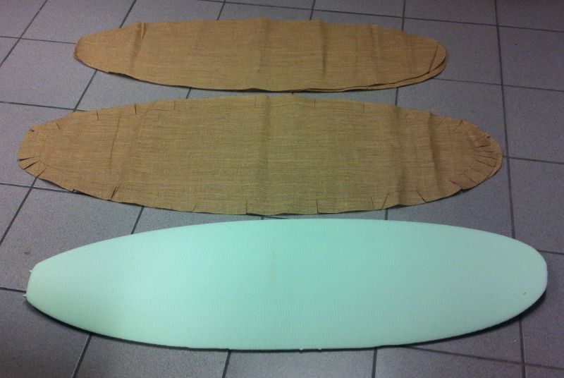
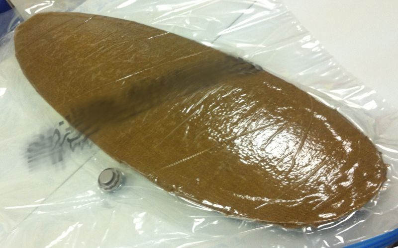
Our task this week was to make a strong and leightweight object with burlap and epoxy.
Download sources of this weeks assignment
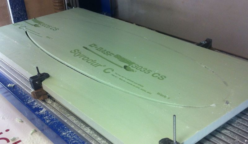
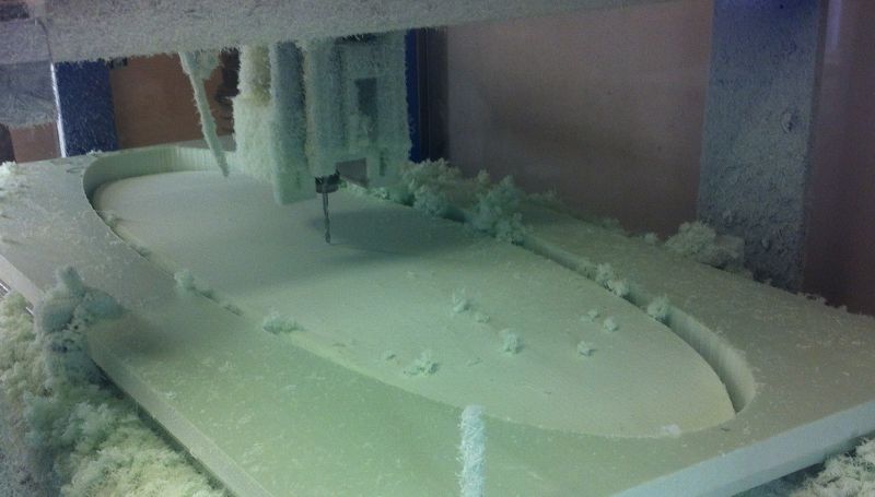
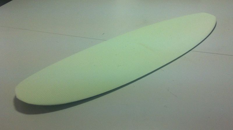
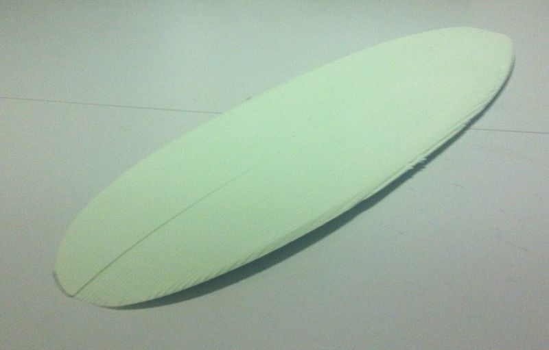
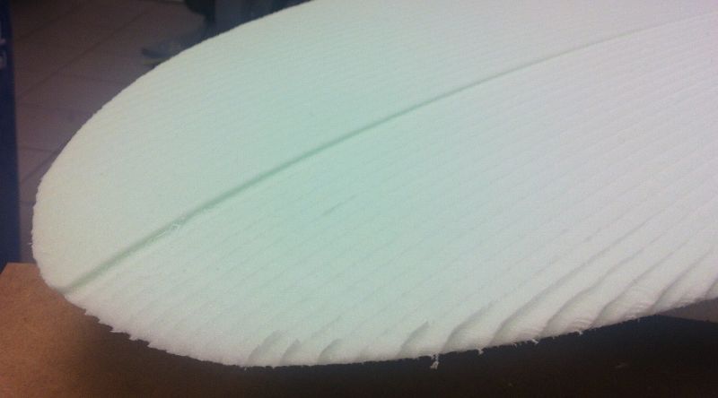
Designing
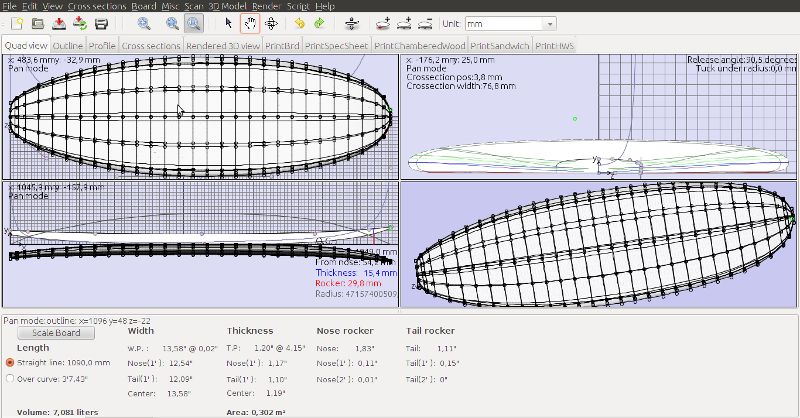
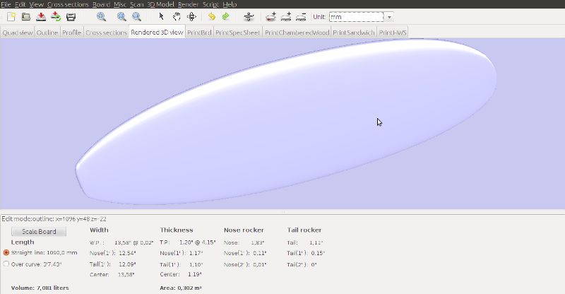
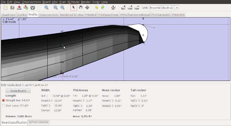
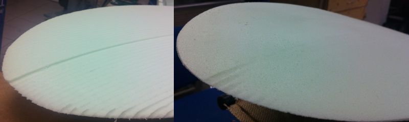
I loved the idea of making a surfboard, as it was shown in the last review session. But I wanted to make a skimboard instead of a surfboard, as it is much smaller and so it is possible to mill in one piece on our CNC.
So the first step was to design the board. I was looking for a specific software to do this and I found out in a quick search that there are some well established tools for this task.
Our task this week was to make a board that controls an output device.
Download sources of this weeks assignment
For my final project I will need to control a servo so I wanted to play with servos a little bit in this assignment.
Designing
Because we have a stabilized laboratory voltage supply in the lab I did not have to use a voltage regulator on my board. The connection to the power supply is realized with small clamps, for this reason I have added larger pads in the corners of the PCB. Moreover I wanted to be able to control the servo from my computer so I added a header for the FTDI cable. But at the power supply voltage rail I added a solder jumper to be able to select which source is supplying the target with electricity.
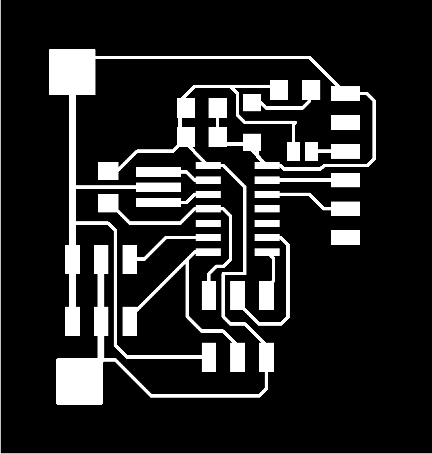

This time I was also milling with my alternative milling bit but this time I got it correct and the result was perfect. After I had completed the milling of the board, I removed the small remaining parts of copper with a knife. Unfortunately I destroyed one trace below the microcontroller so I had to fix that before mounting the components.
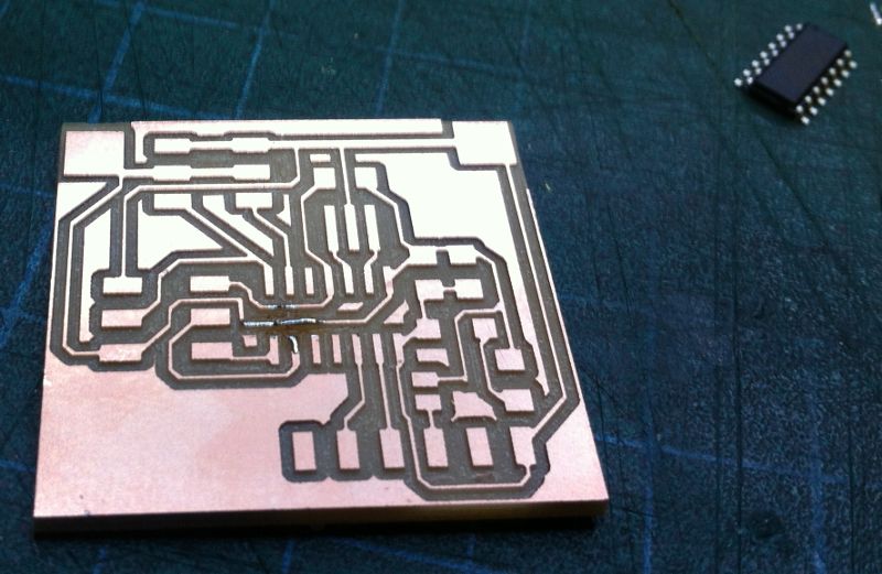
The milled board with the fixed traces
Testing the board
After I finished soldering the board, I tested it the sample code.
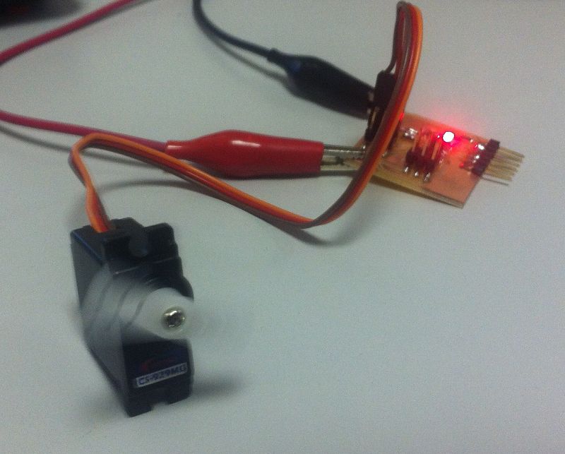
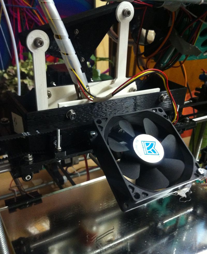
The soldered board is driving a servo
For some reason one of my servos was just jittering (i.e. it did not move as expected) and the other one was missing some repositioning-information. I assume that this is because of the cheap noname servos, as the pulses are nice in the oscilloscope and a good quality servo did not have this issues
What I realized is that the servos are drawing a lot of current in the moment they are moving and for this reason the voltage of the laboratory supply was dropping. For my final project I will place some good capacitory on my board to prevent the rest of the system from issues.
After playing with the board for a while, I added the routine for the UART communication. This way I am able to control the servo from my computer in small steps. I love the power of this approach as this will allow a lot of nice future projects!
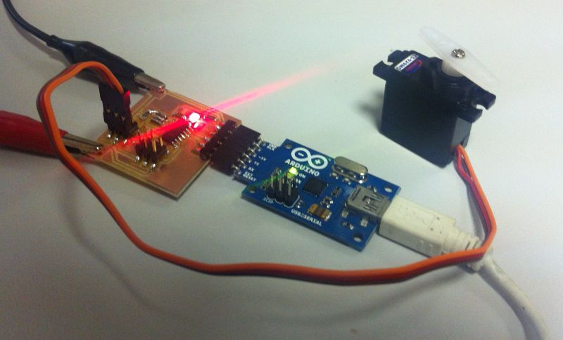
The board is now controlled from the computer
Our task this week was to let two or more microcontroller boards communicate to each other via a networking connection.
Download sources of this weeks assignment
I wanted to use I2C, because I will need an I2C communication for my final project.
First approach
My first idea was to use all the existing modules and let them talk to each other. I figured out that all the attinys that we were using have a USI integrated and all the connection lines from this USI are connected to the ISP header. So I thought that it would be a good idea to come up with small doughter-boards for the USI that enables you to connect them. I also wanted to have a simple and reliable connection between the modules so I used RJ-11 sockets and cables.
Design
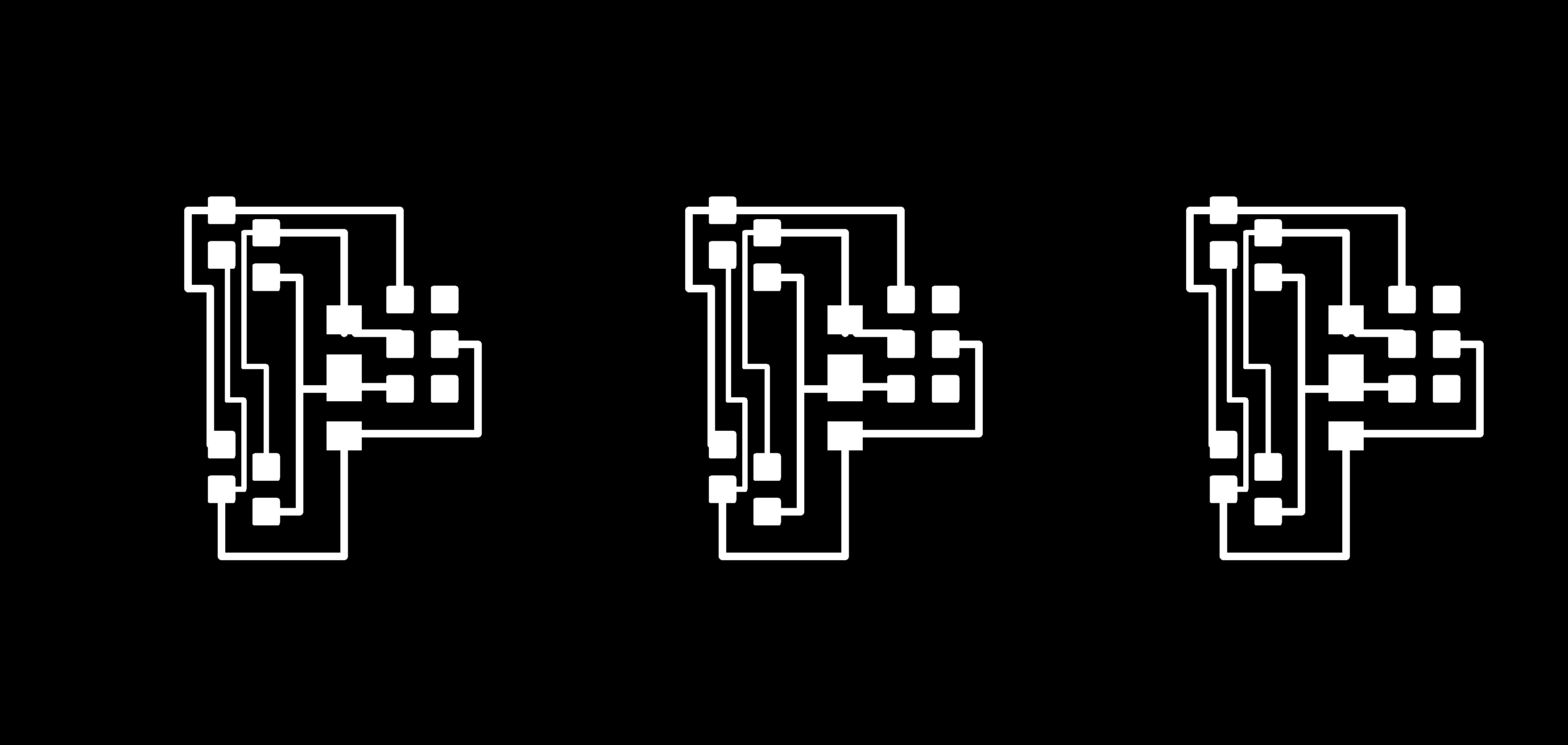
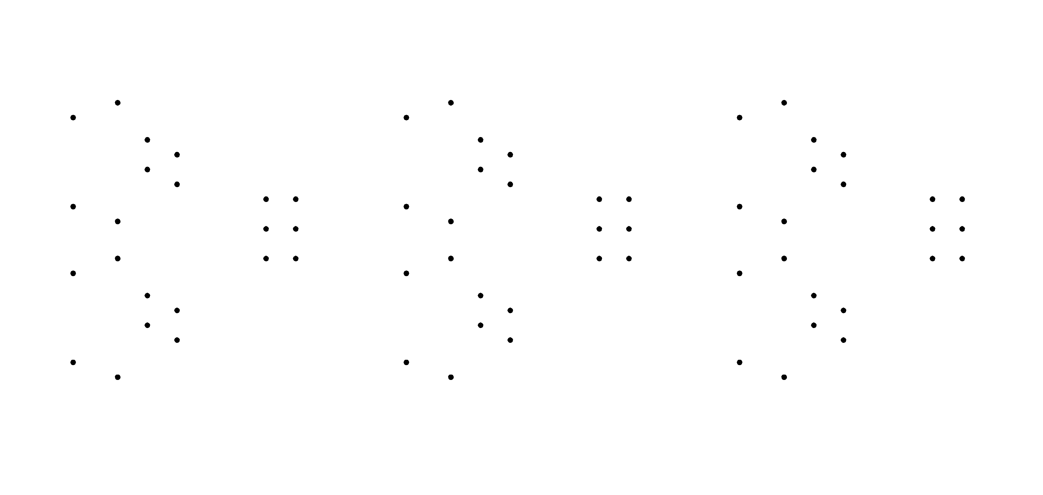
Because I was using TTH components (and I had to connect the RJ-11 headers to the PCB), I had to add an extra step to drill the holes. We only had a 0.8 drilling bit for this task so I extended the area of the pads a little bit. For the RJ-11 connectors, I needed 2mm holes so I made them larger by hand later on.
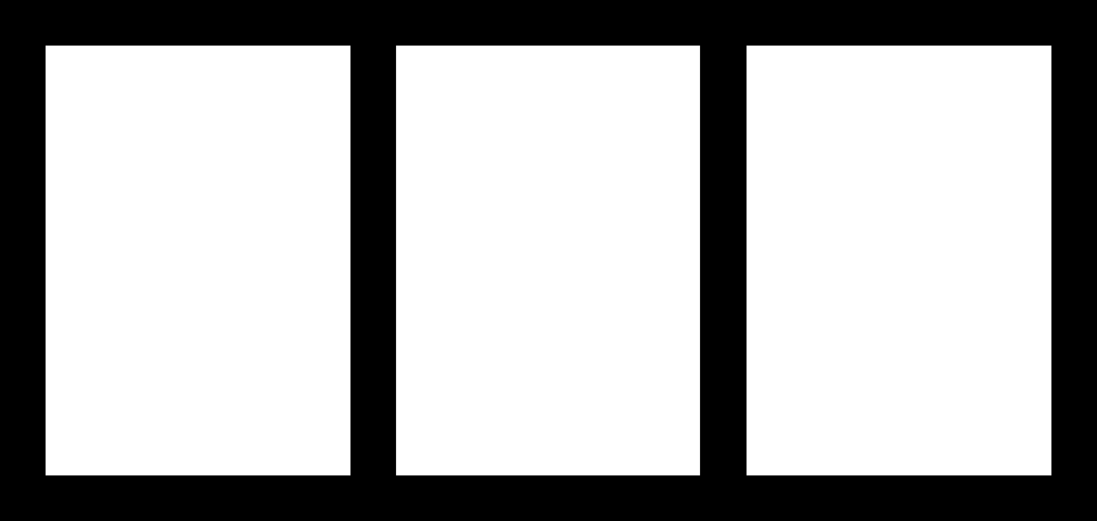
I wanted to have three of these boards, so I placed 3 boards besides each other in an image manipulation software afterwards.
Software
There are some USI I2C libraries available. I was focussing on the libraries that are distributed by Atmel (AVR310 and AVR312). Unfortunately one of the libraries is written only for the IAR compiler so I had to adapt it that it was working with the GCC, too.
Testing
Unfortunately my tests did not work as expected. First of all I was using self crimped RJ-11 cables, that had bad connectivity (I was using a tool for RJ-45 connectors and it did not work very well). The second issue was that the RJ-11 headers on the daughterboards were a little bit too large for some of my boards (or my connection headers were a little bit too short) so the connectivity was quite buggy.
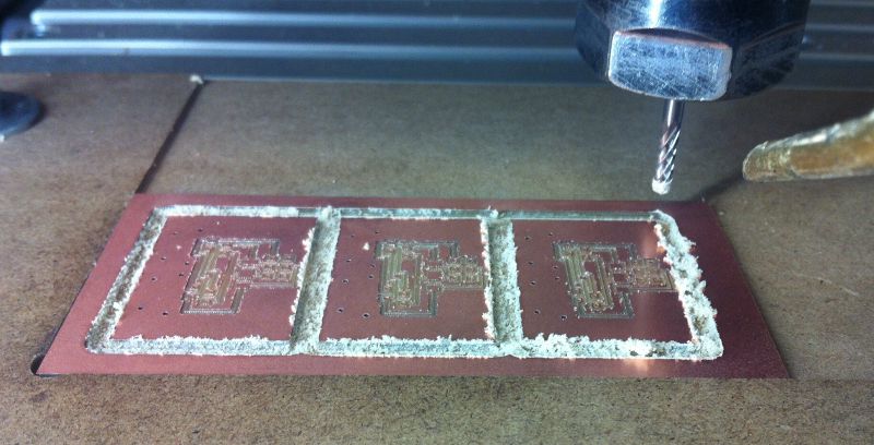
The milled boards
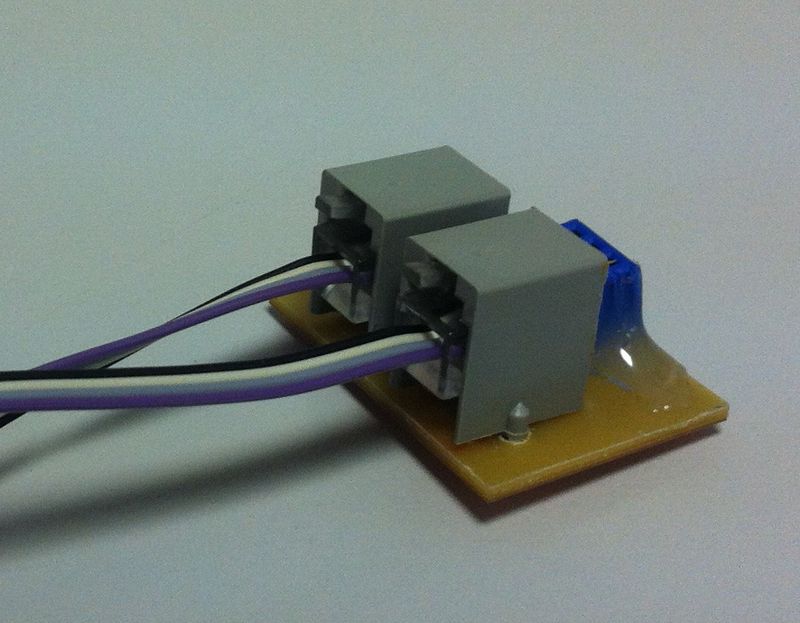
One addon board for the ISP header
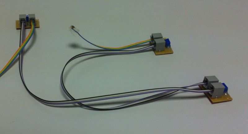
All three addon boards connected via RJ-11 cables
Two example boards connected via I2C from the addon boards
Second approach
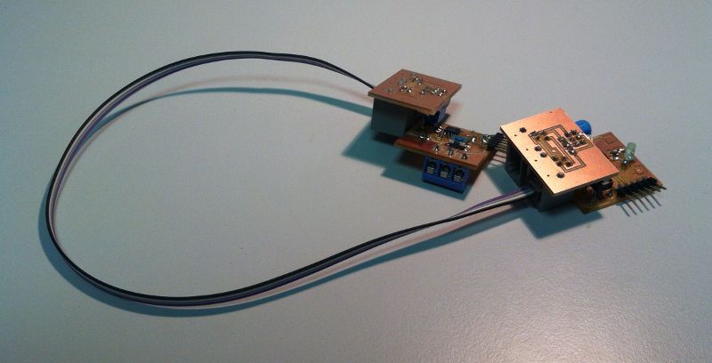
Because the first idea did not work, I wanted to use a hardware I2C unit for my final project. So I designed a board with an ATMega88, programmed it with an arduino bootloader and connected it to a RAMPS board (that is an arduino mega with a sheild to control a RepRap 3D printer).
My controller board has a red LED and so I wrote a small arduino program that receives values via I2C and sets this value as an analog output for the LED. The example worked great and this way I was able to control the brightness of the LED from the RAMPS board!
I was worried a lot about bus speed (because of the long cables) and slowed down the frequency of the bus to 1kHz but as it turned out, it was working nice at 400kHz (but beware that this is a best case scenario as no other components where producing noise).
I wanted to add some more features (like controlling multiple features on the I2C board, adding a checksum, ...), but I did not have enough time to implement that as I had to finish my final project.
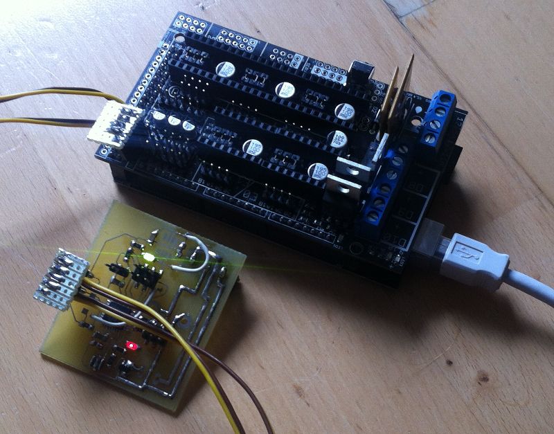
The I2C board with the LED connected to the printer controller board
Now that I have achieved that I really love the ability to use arduino for every AVR board!
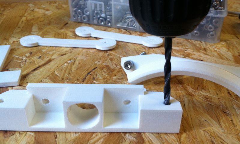
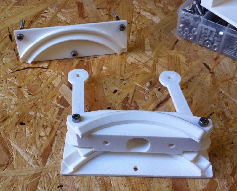
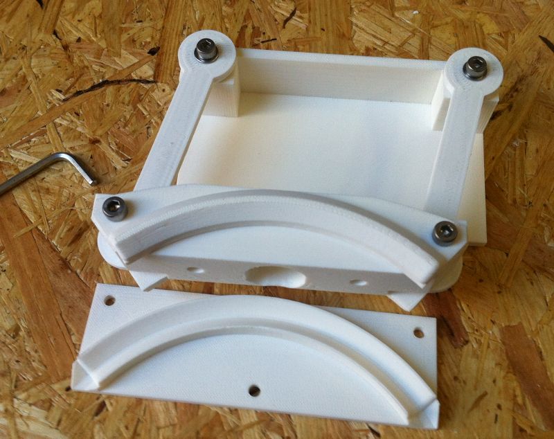
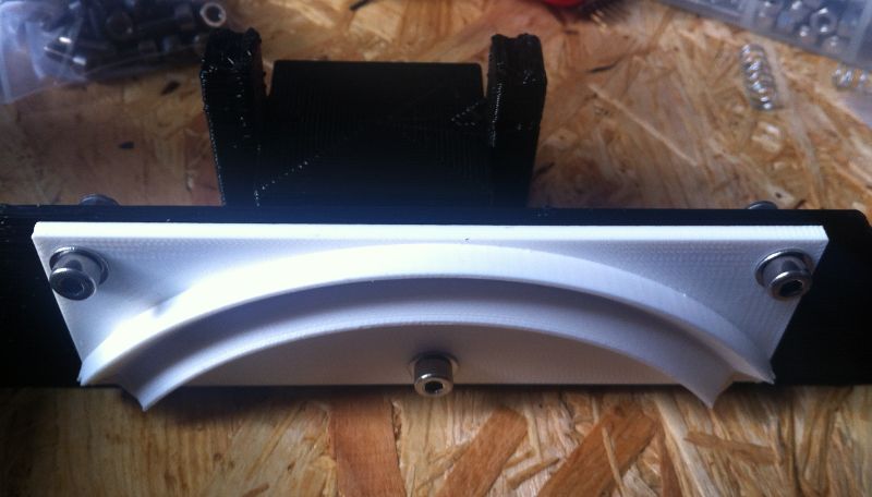
Our task this week was to make a mechanical design for our final Project.
Download sources of this weeks assignment
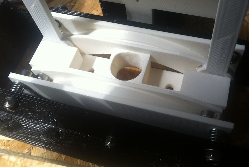
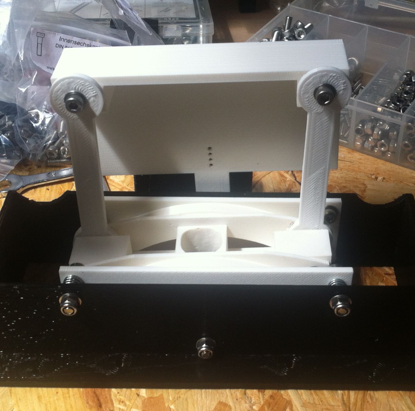
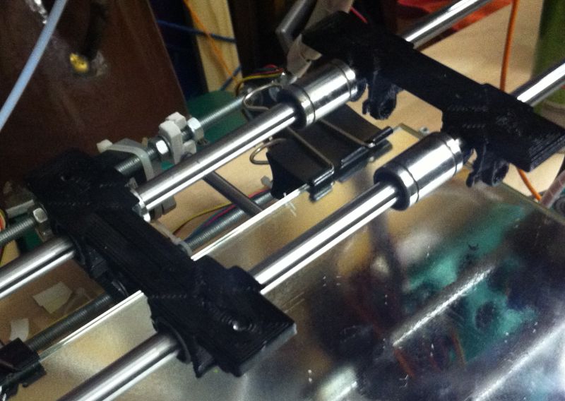
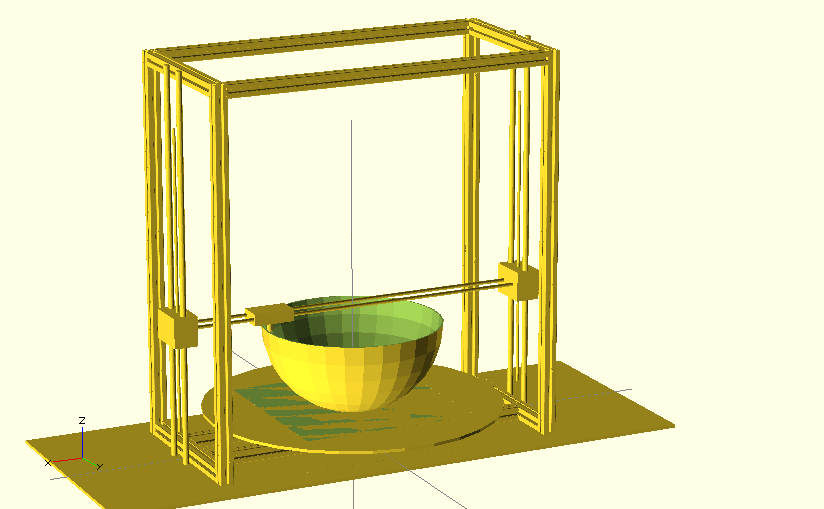
So I started redesigning the rough sketch that I had designed for the final project proposal. I was just fokussing on the the tilting hotend this time. I thought it might be a good idea to keep the design as versatile as possible so I designed the mechanism small enough to fit onto a standard prusa 3D-printer. Moreover I switched from a circular shape of the bushings to a v-shape so that the object is better suited for 3d printing. Furthermore I have separated these parts from the rest of the structural frame for two reasons. On the one hand this allows me to control the orientation for printing to reduce support material and to define the orientation of the ringing on the surface (to align them for perfect matching). On the other hand I can experiment with different materials later on to optimize the behaviour of the bushings.
Our task this week was to write an application that interacts with one of our existing boards.
Download sources of this weeks assignment
I wanted to have an application that lets me control the servo from my computer.
Programming
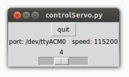
I realized it with python, pySerial and Tkinter.
Basically I started with the term.py and took the board from the output week. In the output week I wrote code that reads characters sent via the serial communication and sets the angle of the servo to a desired position (in 10 steps). So what I did was to achieve the same result as for example hitting 0 on the keyboard by sliding the slider to 0. You have to take care that there is a difference between the integer value 0 (from the slider) and the character "0" (from a keyboard input). So I had to convert the decimal value from the slider to a character, as the output board was expecting that. In python you can do this conversion easily with "str()": character_value=str(decimal_value)
The disadvantage of this approach is that you only get 10 positions from 8 bit, but you can easily adjust the range of the slider with one variable. So if I need more precision I will switch to binary interpretation on the output-board, set the slider to 255 and skip the conversion to charakters.
Our task this week was to decide what final project we want to make and come up with a plan on how to realize it.
Final Project
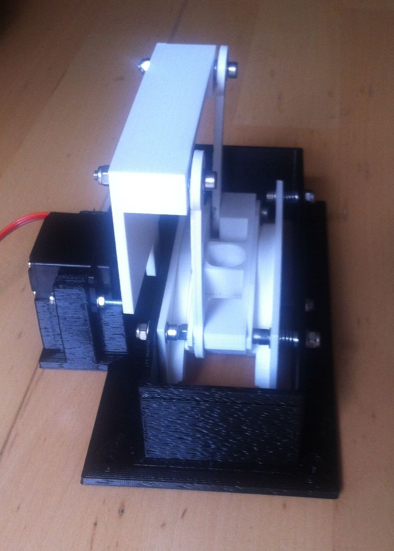
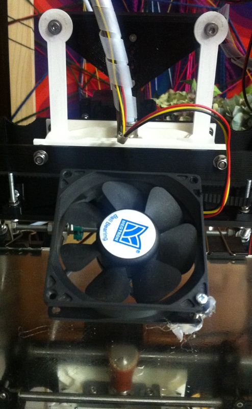
I want to make a 4th axis as an addon for a 3D printer. It takes a bowden-hotend from arcol.hu (actual design version) and should fit on a RepRap Prusa Mendel as a new X-Carriage. As I like the idea behind RepRap a lot, I will go with the standard principle ["take as many standard components as possible, make the connections with 3D printed parts and take some vitamins (i.e. some special parts)"] whenever I can. For this reason I am going to print most of the parts, including the v-shaped-bushings and the v-idler. The axis is driven by a standard sized servo and an extension for the servo arm. Because the printer is controlled by a RAMPS board (the most used electronic for 3D-printers), the control unit for the 4th axis is connected to the RAMPS-board via I2C.
Looking at it in more detail
what will it do?
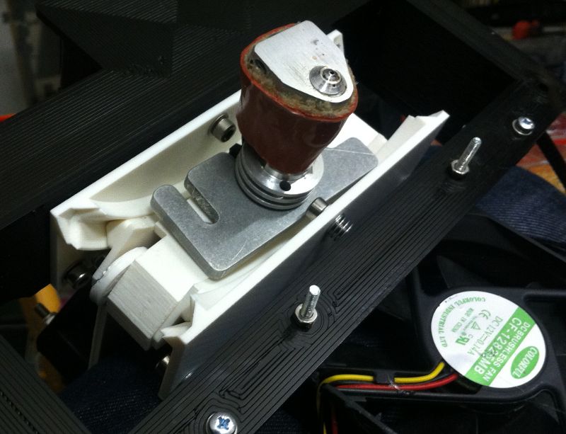
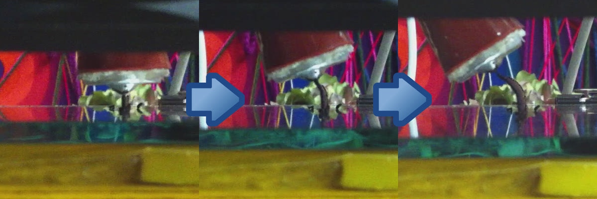
My final project will tilt the nozzle of a RepRap style FDM 3D printer at about +/-30 degrees along one axis (not the z axis).
who's done what beforehand?
The printer (including mechanics, electronics and software) has been developed in the RepRap project, the nozzle is designed by arcol.hu. Concepts for more-axis 3D printers also exist, like the Sextupteron.
what materials and components will be required?
I already have a prusa mendel 3D printer.
Parts needed to finish my project:
servo + servo arm
hinges
bushings
hotend
electronic components
where will they come from?
all the printed parts -> printed in the lab (costs depend on material/printing price)
some M4 screws and nuts -> I already have them, you can get them at RS-Componentes (estimated 2-3€)
some M3 screws and nuts -> I already have them, you can get them at RS-Componentes (estimated 2-3€)
some compression springs -> I already have them, you can get them at RS-Componentes (estimated 2-5€)
servo -> RC-store (1 pc., 34€)
servo-arm -> RC-store (1 pc., 5€)
hinge -> igus (EGZM-04-75, 2 pcs., 3€/pc.)
bushings -> igus (RJZM-02-08, 4 pcs., 6€/pc.)
hotend -> arcol.hu (1 pc., 70€)
filament screw -> arcol.hu (1 pc., 12€)
electronic components:
- ATMega88 -> RS-Components (1 pc., 2€)
- MOSFET FDC8884 -> RS-Components (1 pc., 0,3€)
- L78L05 -> RS-Components (1 pc., 0,1€)
- 2 way screw terminal -> RS-Components (1 pc., 0,3€)
- 3 way screw terminal -> RS-Components (1 pc., 0,5€)
- 4 way pin headers -> RS-Components (1 pc., 0,2€)
- 20 MHz resonator -> FabLab inventory (a few cents)
- some resistors (size 1206) -> FabLab inventory (a few cents)
-- 1x10k
-- 3x4k7
-- 2x125R (or less)
-- 2x500R (or more)
-- 1x10R
- some capacitors (size 1206) -> FabLab inventory (a few cents)
-- 2x100nF
-- 1x330nF
-- 1x1µF
-- 1x10µF
- 2xLED (red and green) (size 1206) -> FabLab inventory (a few cents)
- capacitor 10.000uF -> RS-Components (1 pc., 0,2€)
what tasks need to be completed?
1. get all the parts
2. assemble the mechanics
3. test the mechanics by hand
4. fabricate the electronics
5. add the actor to the mechanics
6. test the mechanics again
7. write the software
how will it be evaluated?
The final project is finished if the nozzle can be tilted to specified angle.
I published the source files of my final project (software and hardware) under the creative commons (by-nc-sa) licenc. This licence allows you to:

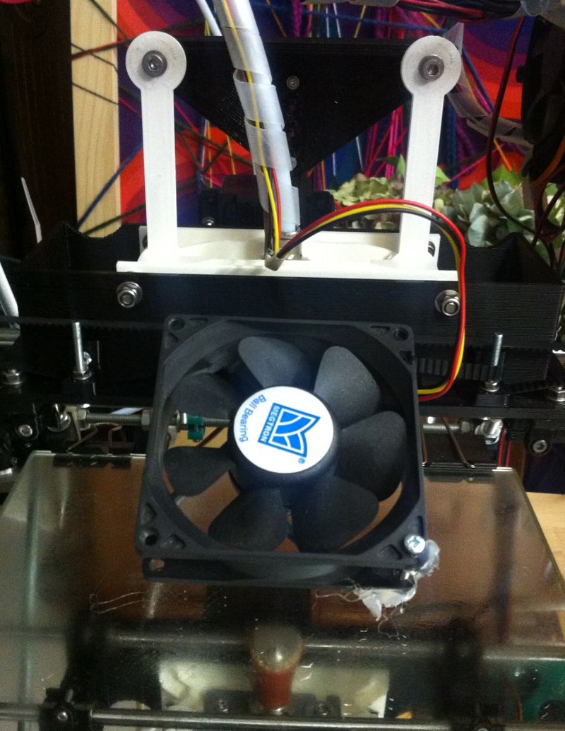
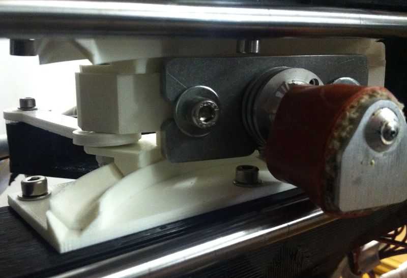
The nozzle is tilted inwards
The nozzle is not tilted
The nozzle is tilted outwards
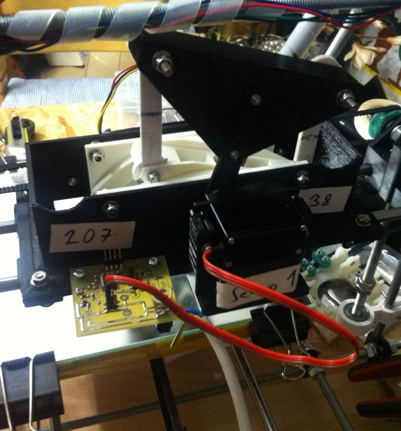
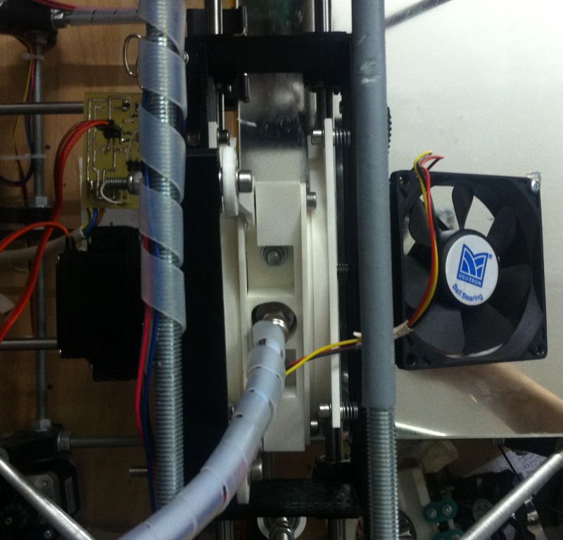
The nozzle is tilted to the left
The nozzle is not tilted
The nozzle is tilted to the right