Molding and Casting

Assignment

Design a 3D mold, machine it, and cast parts from it.

Ideas and Approach

Given I work at a school (that happens to own a simple milling machine, the 2Bot), I was determined to figure out a way to leverage this lesson for the students.  Since it was possible to build molds out of the insulation foam, I decided my project was going to focus on two things I think our teachers could use:
1) Creating molds using the insulation foam, and
2) Making a mold of a topography, because some of our science classes study it all.

And to do this, there are two regions I want to try molding: Southborough, MA (where our school is) and Martha's Vineyard, MA.

NOTE: In order to generate a mold with the 2Bot, we need an STL that gets placed in their "Virtual Worktable" software. 

Design Files

Steps Taken

Creating the Model

The first challenge was finding a way to build a positive mold of a topographical area.  I started doing research and found a bunch of different articles that described ways to get topographical data into an STL file...

With each of these I ran into problems.  Here were some examples of problems and learnings:

Martha's Vineyard of Model

MV Model


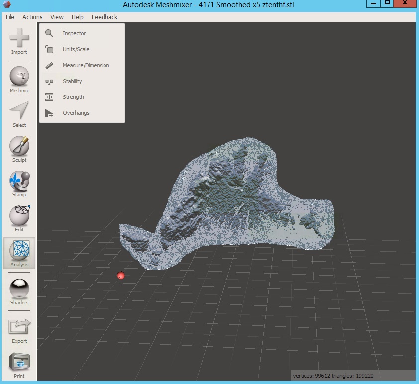
Figure 1: MeshMixer model of MV
MV Printout

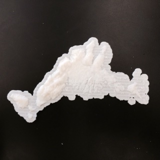
Figure 2: 3D Printout of MV Model
MV Printout

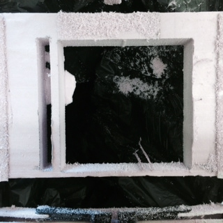
Figure 3: 2Bot printout of model

Two big learnings with the Vineyard:

  1. Doing an island is a bad idea.  It turns out that much of the island's perimeter is a beach so it doesn't show up well.  You can tell this if you look at the small island on the right side.  It barely shows up in the 3D printed model.  The real outline of the island looks like this:

                                                                                    MV Outline

I believe there's a fix for this, but I am not sure and I haven't been able to find the time to try it out.  In a nutshell, I am thinking of using GIMP to combine this outline with the heightmap so that...1) the white area surrounding the Vineyard will be totally black (so that it will be the most carved out, 2) the MV outline above will be dark black so that the beaches show up in the outline and 3) the rest of the heigtmap will be lighter so that the hills won't be as carved out (and will be higher.

  1. The 2Bot needs a base.  When I carved out the save map of the Vineyard, it placed the object at the absolute bottom of the insulation.  That caused it to carve out the entire thing so there was no base. It was a complete fail!

Southborough

Earlier in the year I was able to successfully get the 2Bot to cut out Southborough.  The tools I used were Google Earth and Sketchup.  I learned how to do this by watching the following videoThe problem with this is that Google Earth only allows you to capture a small area.  That gave me the following insulation map of the topography. 

Sketchup with layers

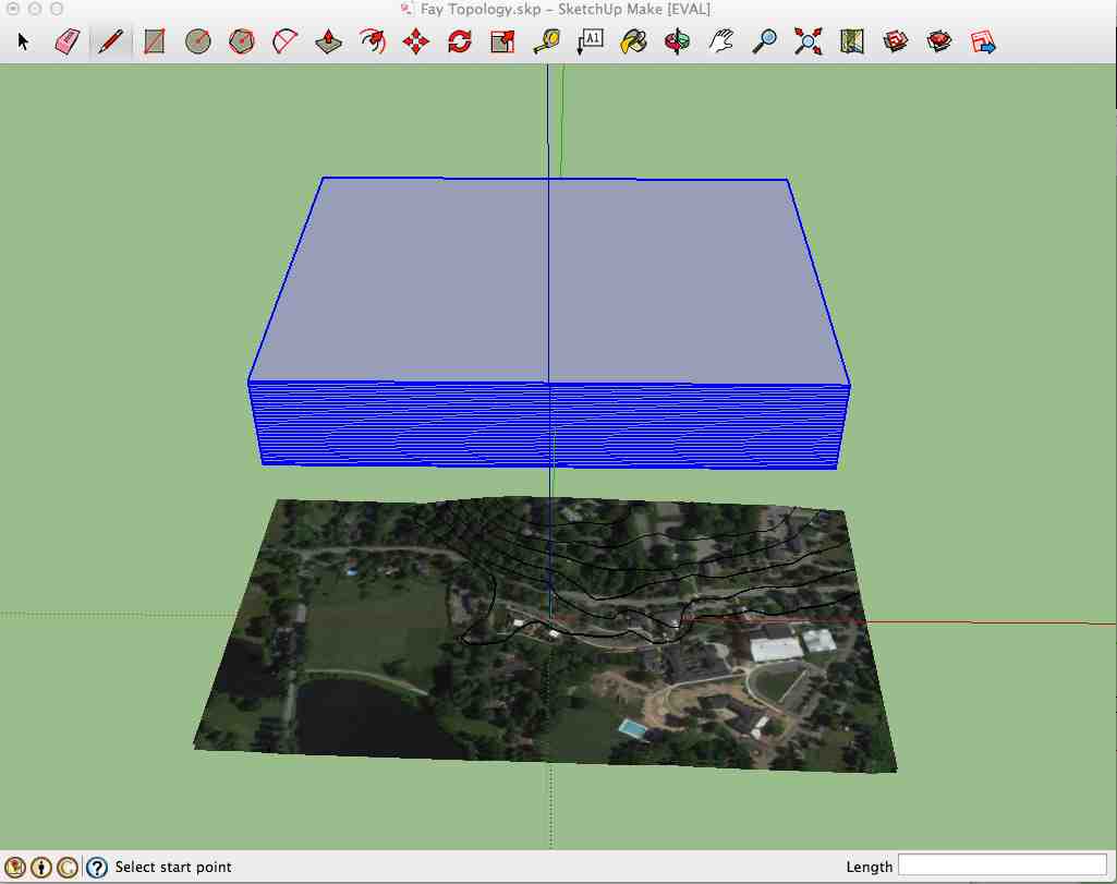
Figure 4: Google Sketchup with Google Earth section and layers that intersect the map data.  Notice you can see our school (and school pool) in the bottom of the image.  I wasn't aware of this before, but Google Earth contains elevation data. 
Sketchupi with
              Contours

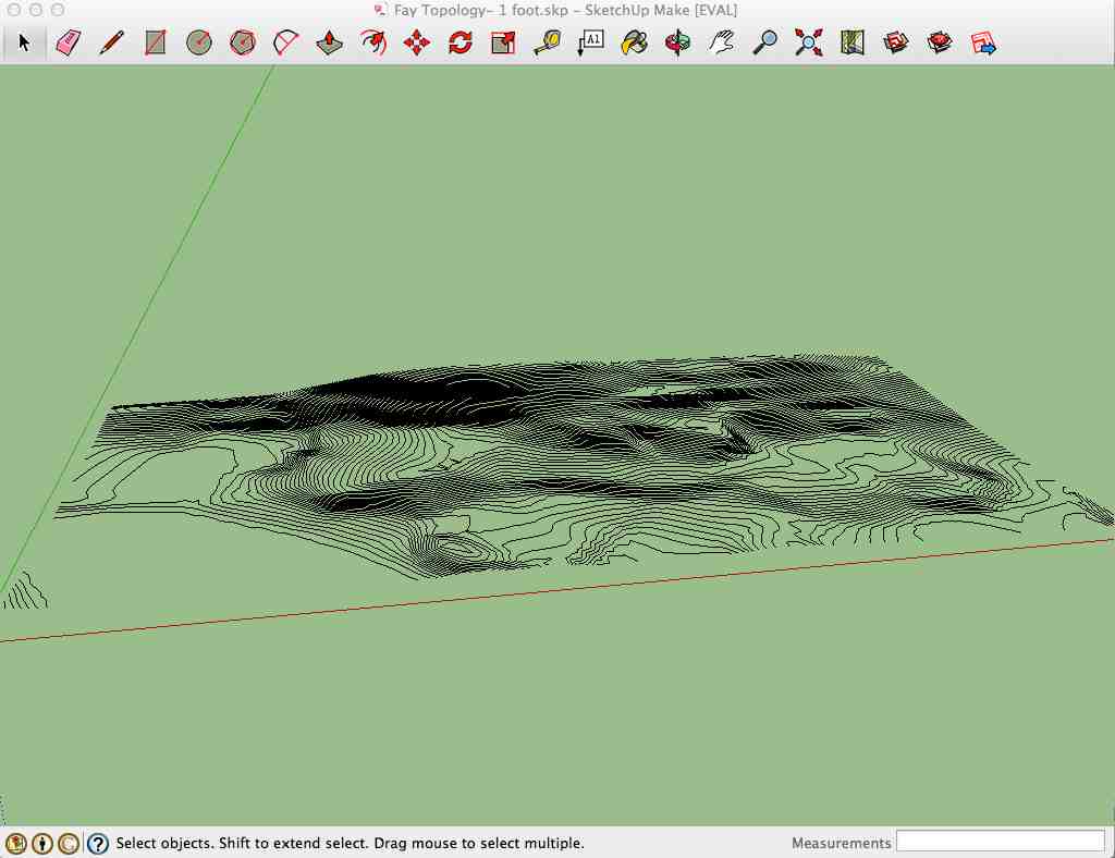
Figure 5: Resulting contour lines where intersections occur. 
Southborough mold
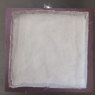
Figure 6: Southborough Mold (with Gesso).  This was the result when I cut this out on our 2Bot. 

At this point I realized that the Gesso on the insulation foam wasn't going to work that well.  That brought me to doing my final round of testing and molding where I wanted to make some progress against the final project.  Here's what happened:

Project Tile Design

During the week 10 Inputs Week, I got velostat sensing when I punched the velostat/copper (here's writeup).  Unfortunately, I didn't get as good a reading when I hit it with a lacrosse ball.  That left us with two theories about why...
  1. Punching the velostat caused a broading impact because my fist has a larger surface area than the ball, and
  2. The ball bounced MUCH more quickly and my sensor was only set to measure every 100 milliseconds so the ball bounced up long before the impact could be registered. 

To isolate this (and to perfect the design) we decided to two things:

  1. Create two different molds for something that will cover the LED and Velostat backing.  We need something to cover the LED anyway so that it doesn't break when hit by ball.  My assumption is that I also need something to distribute the shock of the ball hitting hard.  So we built a 3D object and milled it out with my school's 2Bot.  Then we created two molds with different materials (Dragon's Skin 20 and IS
  2. Change the programming so that it measures the signal on the velostat sensor at a much higher frequency and only reports out when there's an impact. 

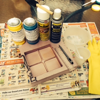
Learning #1: Insulation Foam needs to be prep'ed first
After trying Gesso on my original mold project and reading Matt Pearson's writeup on doing molds with the foam insulation, I wasn't sure if this would work well.  So I went to buy supplies and to talk to the folks at the Rhode Island School of Design store, they suggested prep'ing the foam insulation with two products:
- Bulls Eye Shellac
- Smooth On Universal Mold Release

As it turns out, this worked beautifully.  The Dragons Skin model popped right out mold, which was nice because it meant I could use the same mold for the PMC 121/30.

Learning #2: This stuff is expensive (and I didn't need to use that much)
Because I had the gaps for the wires and LED, I needed to pore enough for about 1/2" thick.  This ended up being about half a $35 bottle.  That would mean that each tile would be about $20...WAY too expensive.  When I do the final project, I am going to build the wire runs and place for the LEDs into the frame and not the tiles. 

Learning #3: Dragon Skin is better for the final project
When I tested the two materials using a sensor, I learned that both seemed to improve the measurement when a ball hit it (initially nothing registered).  And...they both acted the same with similar measurements returned.  The second thing I learned is that the LED looks MUCH better.  The light makes the silicon look cool/bright when used with the dragon skin; whereas, the other material doesn't look as good (it is too dark).

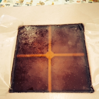
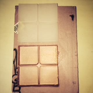
So I started by designing the "tile" that I am thinking will protect the LED (in the center) and it will use the other runs for wires to LED and Velostat. 
Tile design
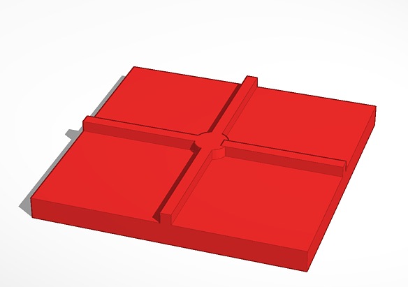
TinkerCAD design of tile
Dragons Skin
                      20 Prep
round 3
                      after poor
Dragons Skin and Prep Materials
PMC 120/30 After Poor Into Mold


Round 1
                      after modl done
2 molds with board
Dragons Skin after mold dried/removed
2 final molds with sensor behind

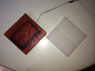
All in all, I am really happy about how this week turned out. Not only did I make progress against the final project, but I learned about a way to use my school's 2BOT to do molding and casting.