Model (draw, render, animate, simulate, ...) a possible final
project and post it on your class page (with as many tools as
possible).
Throughout the past few months I've gotten pretty good at vector
graphics using CorelDraw. This has largely because that's
what we were told to use with our school's Full Spectrum Laser
Cutter. Therefore, for this assignment I am going to focus
on trying to learn / explore:
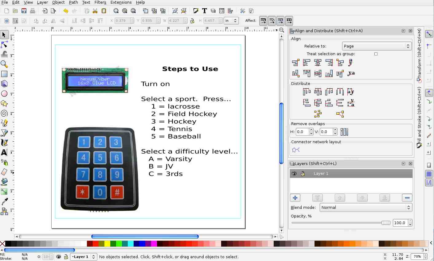
My first goal is to learn Inkscape and so I am going to try to
recreate my vector graphics for the control board into Inkscape
(rather than CorelDraw- which is what I used in the week one diagram). This
proved to be pretty simple, but I ran in to some inconsistencies
that drove me nuts between the two programs. Here are some
of the differences between the two....
| Inkscape |
CorelDraw |
| Clone: The clone feature looks really
promising. I started designing my week 3 project and
it was great using it to model the width of the
material. Unfortunately, I did find it a bit
problematic once I attached the cloned item to other
items. Boolean Logic: I imagine there's a way to do it in CorelDraw, but I haven't find it. The notion of using Union, Difference, etc on objects seems quite useful. Working with Nodes: I get the sense that both programs can do all sorts of manipulations with nodes, but I saw some things that Inkscape does around aligning and distributing nodes that I couldn't find in CorelDraw (and have looked for because I've needed the functionality). Node Placement: OK...I just discovered this and this could be my favorite so far. You can enter the coordinates for the notes. This matters because if I need a node to be .23" away from another node, I can force that. To date I haven't found a way to enter node coordinates. |
Centerline Trace: CorelDraw does a
wonderful job of tracing bitmap drawings. Unlike
Inkscape, you can do a trace that turns a line into a
hairline (rather than a curve. This is quite useful when
trying to trace something you want to vector cut (e.g. the
perimeter of something). Object Manager: While Inkscape does have the concept of the XML Editor, I think CorelDraw's interface and layer functionality seems better. For example, you can specifically say whether you'd like to print a layer in Corel. Text Formatting: Unless I was missing something, CorelDraw provides many more options for formatting text. For example, I couldn't find a way to underline my text in Inkscape. |
One thing that I was quite happy about was the fact that I could easily print from Inkscape to our laser cutter (a Full Spectrum laser). I had tried this before, but it wasn't until someone on the fabacademy thread mentioned setting your line width to .01 inches that I finally figured out how to do it. Here's the most useful part of the email: "The linewidth crossover point between rastering and vector cutting is a function of the raster dpi setting. i.e. for 600 dpi it is 25.4/600 = 0.042mm ; at 1200 dpi it is 25.4/1200 = 0.021mm so 0.01mm line thickness is a safe bet as it will always vector cut no matter what dpi setting you are using on Epilog mini 40w.". Thank you to Dr. Eddie Kirkby for that information.
All in all, this was REALLY useful as it helped me to realize
that Inkscape isn't that bad and that I should be promoting it
(and potentially using it) at our school.
Here is what I ended up with in Inkscape. Not that
different from what I had with CorelDraw, but I finally learned
how to get around Inkscape.
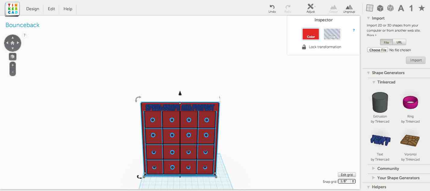
Here's the final TinkerCAD sketch of the bounce-back that I'm
hoping to use for my final project. It's rudimentary, but
given it's the first time I created my own 3D model (rather than
downloading or scanning one) I figure it's a good start.
I found TinkerCAD easy to pickup, but it probably won't be that
useful as my models increase in complexity. Having said that, I
did find a new function that could be really useful to me at
school...Export to SVG. Apparently, once you have your model
you can export parts to a 2D SVG file, which can then be laser
cut.