Choose and Learn about LEDs using Arduino
The first thing I decided to do was to pick a specific kind
of LED that I thought I could program. For this, I
went with the Adafruit
NeoPixel. I went with this because I wanted to
use as few pins as possible and the NeoPixels come with the
ability to control them using only one digital pin. I
was also impressed by their documentation on things like the
power
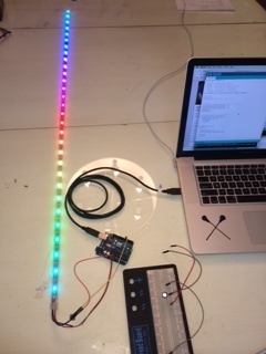
handling. So for the first step, I decided to try to get the strip of LEDs working with the Arduino. Theory being, if I could get the basic program working I'd learn about the wiring and the code needed to drive the strip. I took their example code and fixed a few things up (like the number of LEDs).
Lesson 1: Don't need resistor/capacitor
The first big lesson, some of their best practices messed me up. When I tried to wire it all up using the capacitor and the resistor that they recommended, nothing worked. When I took them out of the mix, things started working. I also noticed that there was a resistor at the start of the strand so I believe they built this in.
Lesson 2: 5v is enough to power strand
The 5V off the arduino seems to power the lights just fine. I was worried because their power handling instructions seemed to suggest that this might not work. Given this, I am thinking my test board should work when I try to power it all using my board.
Lesson 3: Wiring
When wiring this, I found that I needed to wire the following:
- Ground needed to go to both the black wires
- Control could go into any digital port, but I put it into pin 6
- 5V into the Arduino 5V pin
Program the Arduino strand to light up based on power
When a child hits the bounce back on my final project, the strand will need to only light a few lights at the bottom of the shot is weak and it will need to light up tons/all the lights if the shot is hard. And I am thinking that the color could change based on how hard (red if not hard, green if really hard). So here's what I want to program...- weak shot: only a few lights light and have lights be red
- ok shot: medium amount of LEDs light up and they show up as yellow
- hard shot: all lights go off and show up green.
To make this easier, I am going to program the arduino to do this and then I am going to port the code over to work with by board.
Lessons 1: Colors Represented by Unsigned Integers
This is likely unique to the NeoPixels, but color (0,0,0) - parameters are R, G and B- makes the lights go dark. That's good as I'll need to do that before someone's shot goes of. Other colors to remember: Yellow = 255, 255, 0. Red is obviously 255, 0, 0 and Green is obviously 0, 255, 0. To make programming easy, I decided to define constants that I can use to just reference the color without having to worry about the values. Another note: when I created the constants, I used int. This didn't work. I had to set the colors to uint32_t instead. I guess the color values can be between 0 and 64K.
I also created a function that I will be able to call that will take two parameters...color and percent of lights to brighten. This will be what I will use to get the lights working
Here's the arduino code I ended up with.
Program single LEDs with Arduino
Lesson 1: Pay attention to direction of digital signal
The first time I wired this, I was sloppy with the direction of the digital signal. The NeoPixel's require the digital signal to go in one direction and one direction only. This is depicted by arrows. Unfortunately, I mis-wired one of them so they didn't work at first.
Lesson 2: They are fickle
It took me awhile to get them lighting correctly because the connections on the third and forth pixels didn't light consistently. I finally messed with the wires enough so that they eventually worked, but I will need to take this into account with the final bounce back because it will get hit by the ball and that will need to be really secure. I will definitely need to solder it all.
Get working with ATTiny
Now that I have things working with the Arduino, I need get this working with the attiny and the board I previously designed. This might be hard because ...1) the timing is different and the NeoPixel's require precise timing, and 2) will the 1K resistor and/or 499 Ohm resistors work?To start this, I read through the following tutorials:
http://m.instructables.com/id/
and
http://www.correderajorge.es/running-neopixel-ring-with-attiny85/
In order to get this working with my board, I am going to have to be creative about the pins and their use. Here's what I need...
- +5v to power the LEDs (will use A3, as this doesn't have any resistors and will use it as a digital output)
- digital out pin to control the lights (will use A7 as this is the one with the 1K resistor)
- two GND pins, which is good news because I have many available
Lesson #1: attiny needs to run more slowly
The first problem I ran into was that I was getting errors when I tried to compile and upload the attiny code. When I ran the compile I got the follow error:
"/Users/pfearey/Documents/Arduino/libraries/Adafruit_NeoPixel/Adafruit_NeoPixel.cpp:383:3: error: #error "CPU SPEED NOT SUPPORTED""This was because the NeoPixel's couldn't run at 20MHz. To fix that, I got some help from Shawn and updated the boards.txt file with the following:
attiny84-20.name=Attiny84 (external 16 MHz resonator)I was then able to "Burn the Bootloader".
attiny84-20.bootloader.low_fuses=0xfe
attiny84-20.bootloader.high_fuses=0xdf
attiny84-20.bootloader.extended_fuses=0xff
attiny84-20.upload.maximum_size=8192
attiny84-20.build.mcu=attiny84
attiny84-20.build.f_cpu=16000000L
attiny84-20.build.core=arduino:arduino
attiny84-20.build.variant=tiny8
Lesson #2: attiny / avr programming needs different programming
The problem was, I couldn't get it to compile when I tried to get the attiny to use the internal clock at 8 or 16 Mhz. When I tried to compile I got the following error:
/Applications/strandtest_with_attiny_ino.ino:339: relocation truncated to fit: R_AVR_13_PCREL against symbol `__mulhi3' defined in .text.libgcc section in /Applications/Arduino 1.0.5.app/Contents/Resources/Java/hardware/tools/avr/bin/../lib/gcc/avr/4.3.2/avr25/libgcc.a(_mulhi3.o)
http://forum.arduino.cc/index.
As it suggests, I unzipped and replaced the ld file in the Arduino program. Once I did this, everything started compiling.
Lesson #3: attiny doesn't give off enough power
Now that I had the code compiling and downloading to the attiny, I ran my program. Nothing happened. No lights. No nothing. I also couldn't figure out a way to troubleshoot because my voltmeter wasn't going to be able to measure the digital signal because it changed too fast. Shawn confirmed this...you'd need an oscilloscope to troubleshoot that. This is where Shawn saved me (again)! He immediately pointed out (my first) problem...I was using the 7 pin from the attiny to power the LEDs. My theory was that, if I set a pin to high, that it would put out 5 volts- enough to power the lights. I was wrong. Shawn pointed out that the attiny only puts out 40 milliamps (see page 160 of the attiny85 data sheet). It says the following:
DC Current per I/O Pin ............................................... 40.0 mA
DC Current VCC and GND Pins................................ 200.0 mA
And that isn't enough to drive the lights. To fix this, I started plugging the power into the 2x3 programming header and the ground into the same header's GND pin.
Lesson #4: Using port B (rather than port A)
To drive the NeoPixel, I connected it to A3/pin 10, which is part of port A. My thinking was that this was programmed to a pin that had no resistance. When I asked Shawn about it, he started reading the Adafruit_NeoPixel.cpp file and he found the following code in the "// 8 MHz(ish) AVR" section of code.
// Squeezing an 800 KHz stream out of an 8 MHz chip requires code
// specific to each PORT register. At present this is only written
// to work with pins on PORTD or PORTB, the most likely use case --
// this covers all the pins on the Adafruit Flora and the bulk of
// digital pins on the Arduino Pro 8 MHz (keep in mind, this code
// doesn't even get compiled for 16 MHz boards like the Uno, Mega,
// Leonardo, etc., so don't bother extending this out of hand).
// Additional PORTs could be added if you really need them, just
// duplicate the else and loop and change the PORT. Each add'l
// PORT will require about 150(ish) bytes of program space.
Once I changed the attiny port I was plugged into from A3 to pin 8 / PB2, things started working!