Measure something: add a sensor to a microcontroller board that you've designed and read it.
So I wanted to try to use my board that I'd built and I wanted to
start making progress on my final project. The big question
I've been having is whether the velostat will work for my
pitchback/final project.
The first step was to get a sense of how velostat was
designed. To that end, I looked through the following...
- a
pressure sensitive floor
- DIY
bend sensors
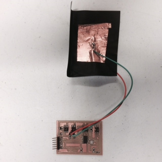
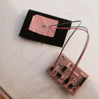
| First I setup the velostat so that I could plug it into my board. I soldered some female wires to copper strips and put them on different sides of the velostat. | |
On my board I have three possible pins I could use to read the
sensors (aka there are headers already soldered and connected to
these attiny pins):
8 It is
directly attached to the attiny pin with no resistor in
between.
A7 It has a 1K resistor
between the sensor and the pin
A3 It has a 0K resistor
between the sensor and the pin, and with internal pullup it goes
to 10K
A2 It has a 0K resistor
between the sensor and the pin, and with internal pullup it goes
to 10K.
These matter because I am trying to figure out the resistance and whether I can use the board I made to do my testing.
First, I needed to get a sense of how much resistance the velostat had. This mattered because it is best to offset that resistance with a corresponding resistor with the 5v pulllup. So, I tried to measure the resistance of the velostat by connecting it to a voltmeter. When on 2K setting, I was getting a reading of 0.366 (with no pressure). That suggests that the velostat has a resistance of 300 Ohms. We then put pressure on the sensor (simulating what happens when ball hits it) and the resistance went to 500 ohms. So we now have our range.
First lesson, the internal pull-up has a resistance of
10K. Shawn reminded me of this. We also worked
through the math and it started to make more sense because....
| That's when I realized I could hack my
board. When I originally setup my board, I had
imagined having an LED hooked up to the 7 pin (hence my
putting a 1K resistor). In this case, I realized that
by making the 7 pin an output pin and by setting it to high,
I could use the pullup resistor in A3. So I soldered another wire to the copper plate and wired it up in the following way: Side one (with only one wire): Wired to the ground. Side two (with two wires): Wire 1: To pin 7 so there's a 5V Wire 2: To pin A3/3, which is what will be doing the readings |
 |
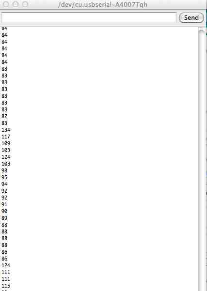
| When I ran the following
code, I got the following result (using the small 1"
patch of copper)... Here's what was going on... When I put pressure on the copper/velostat, the values jumped up to 134 and 124. That's good because it suggests that there's a noticeable change that I might be able to capture in code... ...BUT... Notice the gradual decrease. I didn't realize this, but after I released the pressure the value gradually dropped (I figured it was going to drop immediately). LEARNING: I am going to have to program this to account for the gradual drop by doing something like taking the the average of a bunch of readings. NOTE: It took about two to three seconds before the value dropped to the steady state (~85). QUESTION: Will the results be consistent if I create a bunch of these copper/velostat combinations? Will have be able to use the same programming logic for all pairs or will I need to custom calibrate/code for each section. Will have to figure that out later. |
 |
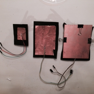
| So I decided to try three different kinds of
plates... #1: 1" copper soft pad (leftmost pad) #2: 2"x3" copper soft pad #3: 3"x3" copper boards (rightmost item) And here are my findings: - The values returned are different when try different plates. When I use #1, the values go between 18 and 50. When I use #2, the values go between 30 and 150. When I use #3, it doesn't really work. Primary reason is because the stiffness limits the impact on the velostat. |
 |
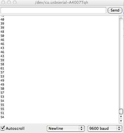
| Gradual Pressure For this test, I just pushed down on the materials. The values went up, but they didn't go up very quickly. As you can see from the results, the values didn't go up much. They went from 43 to 59. That's not a big jump. |
 |
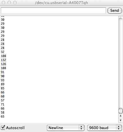
| Crumple While this isn't a test that will help me with the final project (because the ball hitting the bounceback can't crumple the copper), I thought it would be good to test this to see if this caused a change. Notice the results on the right... The value goes from 32 to 108/132. That's a good, big jump, but it still seems a bit more gradual (partially because the crumple takes longer than the punching below. Bottom line: interesting results and better than the gradual pressure, but this isn't something I will use for the final project. |
 |
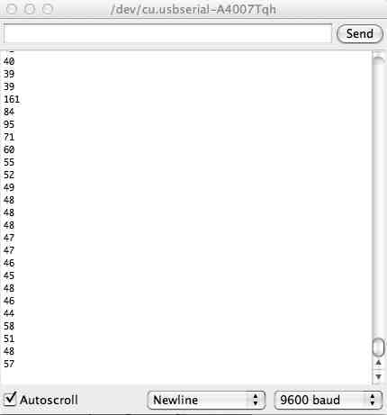
| Hitting with fist To execute this test, I just punched the patch of copper. And the good news...hitting looks like the best option. Unlike the others, the values jumped a huge amount, and they jumped quick. Notice the change from 39 to 161. That's the kind of change I was looking for. The other thing that's interesting about this is that it quickly responds back to the steady state (in the range of the 40s). Bottom line: there's hope! This might work for the final project. |
 |
| Hitting with Ball Now that I've got it responding to some form of hitting, I wanted to simulate the real situation...a ball hitting the material. The problem was, it never registered the hit. Why would it register my punching it, but not the ball? Then it occurred to me... I was just doing an "instantaneous reading" every 100 ms, which I'd put in place when I couldn't read the debugging I had spewing across the screen. And my hitting with my had was much slower than the lacrosse ball bouncing off. That made me change the program around so that I'd track max/min values and would report when I hit different values. When I did this, I found that, without the 100ms delay it was registering a hit with the ball. |
/* In this round, I am going to "simulate" the 1K pullup resistor by using the 7 Pin, which has a 1K resistor in between the attiny and the connector for the sensor. So the wiring will be... One side 1 of the velostat I'll have it connect to the ground On side 2 of the velostat there will be two connections: 1) to the 1K pullup resistor, and 2) to the A3 pin that plan to read And to get the 7 pin to be a pullup resistor, I will make it high to simulate the connection to the +5V. http://arduino.cc/en/Tutorial/AnalogInput */ #include <SoftwareSerial.h> |