Mechanical Design
For more details about how I did the GIF check the Digital Model Week
One unit
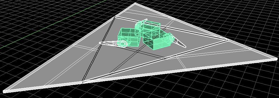
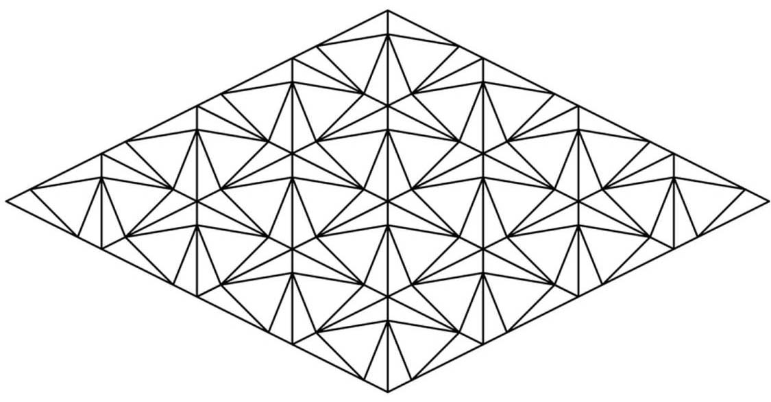
This week as well is a step for my final project, I had to study the behavior of the surface I'm making. Its based on the origami grid hence it should fold and unfold equally without changing in dimension even if used for a long time. The project is divided into panels, each panel has 4 parts, three of them is movable and attachable to the next panels while only one is fixed where the servos should lie on
.jpeg)
.jpeg)
Digital Mechanism
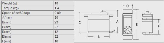
While modeling the design I used this reference from the servo's DATASHEET to give me the exact dimensions of the motors. According to these dimensions I tested the minimum dimension of the bed with respect to the servos size, direction and the range of freedom I wanted to apply to have (from 0 degree to 90 degree).
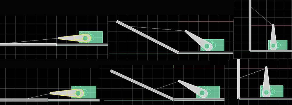
On Rhino I also testes where exactly should I place the pulling wire. I had two alternatives either at the lower or higher part of the unit. From what I read online I went with the higher point to reduce the load applied on the servo arm.
Choosing the Material
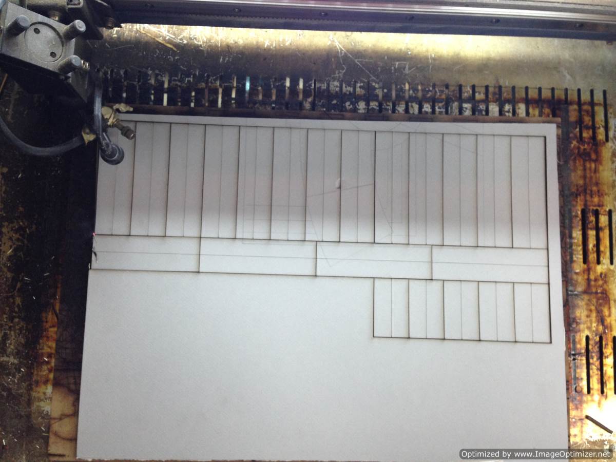
I started with the single unit design made it out of thin compressed cardboard. I used the laser cutter with Cut a high power of 100 and a moderate speed of 80 with the engrave I used less power and moderate speed as well at 80 but I had to go over the engraving once more as I wanted the mechanism to be as loose as possible.
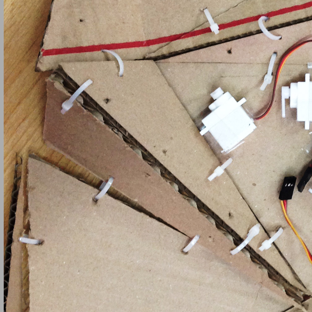
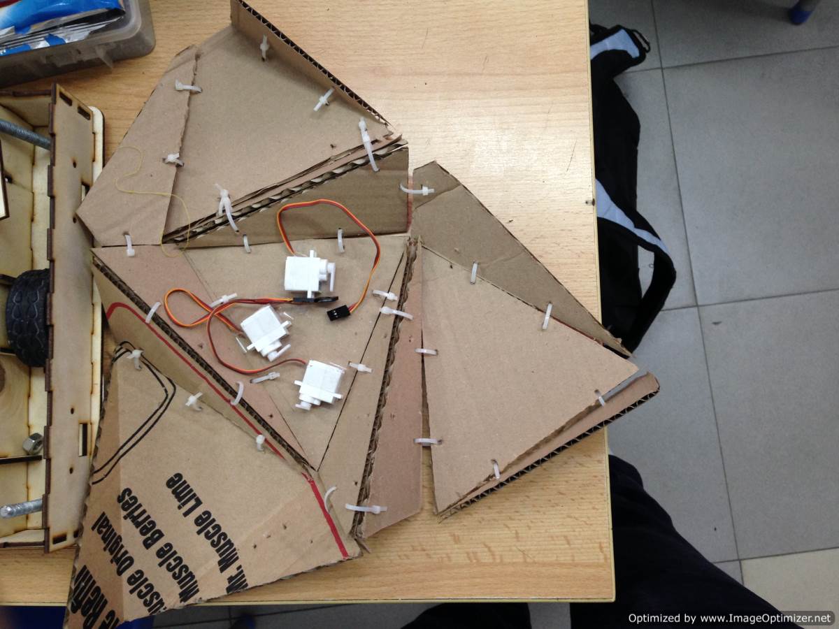
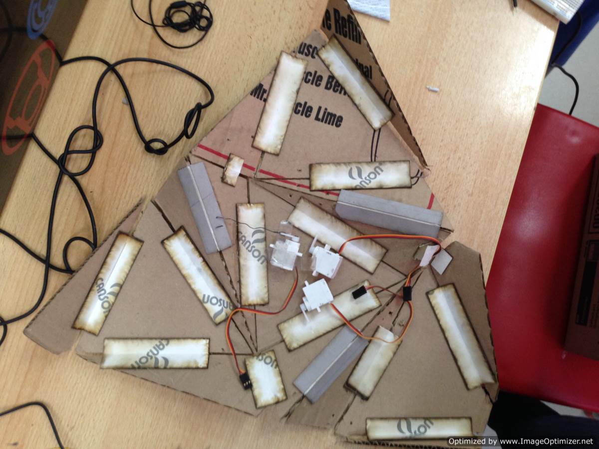
as shown in the picture the three servos should lie on the stable triangle fixed with crossed supportings of tape. The crossed supporting would help resolute the torque force applied on the servo while pulling up the sides while the tape is temporary for the current trial, later on I will develope it into something built in the body of the unit. To pull the movable triangles I used fabric wires they were good at the tension phase (pulling the unit up) but they were not good enough at the compression phase (pushing the unit down) so I had to make the engraving as loose as possible depending on the gravity and the surface's weight to pull it bach down again
WATCH A VIDEO
Connecting units
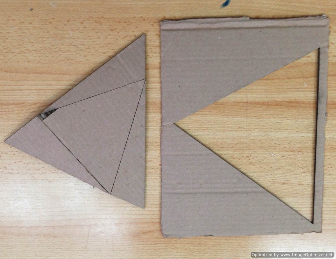
This system works with synchronizing the motion of the movable parts all at once an at the same degree. The manual test I started with meant to make it as a one continues surface with only engravings that help it move up and down. But this model's scale was too small, when I tried the same way on the right scaled model it wasn't lose enough, also was very hard and heavy for the motors to move it up and down.
so I decided to separate it into smaller units. The idea now is to try out the connection between the unit neighbours that makes them move together. I came out with two different techniques each one has PROs and COs
First
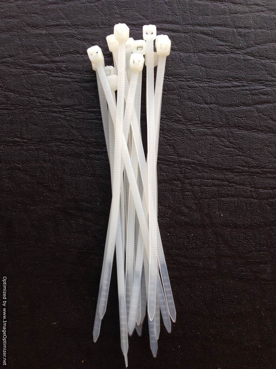
one was using these plastic connectors, where each side has three holes two at every edge and one at the middle. Same thing goes with the neighbour unit, then these plastic connectors are sewed in them to hold them together
This connection was easy at casting, and saved a lot of time but it both edges kept bumping into eachother. The friction was too high and gave minimum degree of freedom.
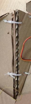
Second
One was this connectors I used a lighter material for the body and stiffer material for the connectors to minimise the load on the servo yet make it as stiff as possible. This and by all means was a better solution it kept the edges aligned during the motion up or down, gave all the degrees of freedom wanted from 0 till 90
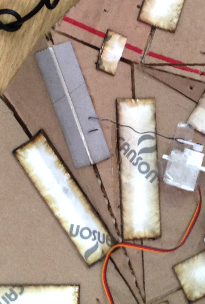
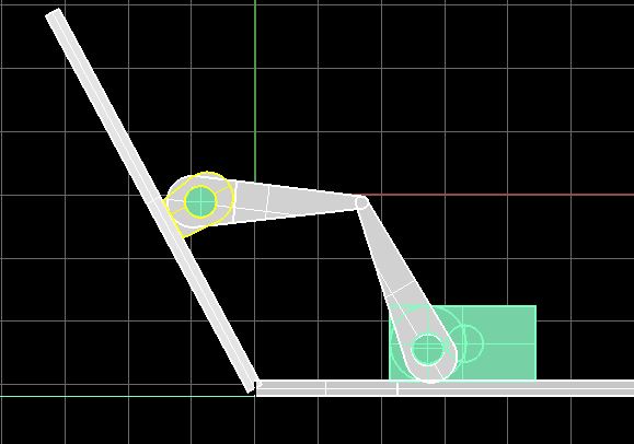
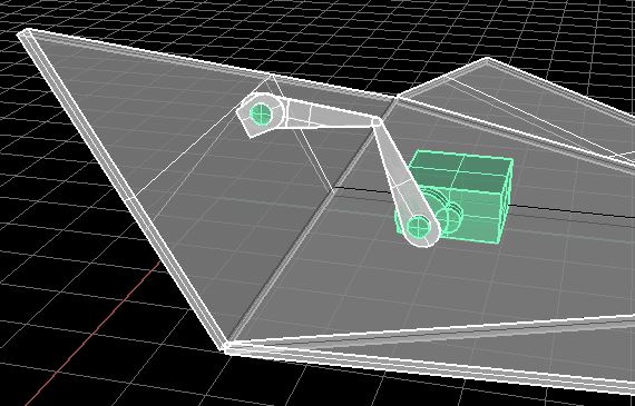
After the first test, Wires were not very good at compression as it was with the tension so I will have to change it with something more stiff. I designed this two joint arm. First joint is at the movable surface and the other is at the end of the servo arm.
Download The Design Files
"The surface Layout" on AutoCAD 2013
"The surface Supporders" on AutoCAD 2013
The 3d designed unit on RHINO5
The GRASSHOPPER defenition
"The Proposed 3Djoint" on RHINO5