OutPut Devices
CHECK THE INPUTS WEEK FIRST
After modifying the library, the program compiled and the board got programed I used the external battery for the power supply. The board passed the smoke test so there were no short circuits B U T since the motors started moving the regulator started getting warmer and warmer I rechecked all the internal connections and the connection to the power supply there was nothing to be fixed!!

So I replaced the regulator with a regulated power supply from a 7805 regulator done locally at our lab on a breadboard using 100 uf, 100 uf and 10 uf capacitors This solution made it better but still I needed to redesign the whole board. This solution made it better but still I needed to redesign the whole board.

The New Board
Asser in our LAB was developing a similar board for his final project so I modified his design to remove the unwanted components and added others for my final project. I was planning to use this board as a bridge in the networking and communication week so I added a serial communication pin for the network which also would be helpful for the digital interfacing. My board should run 6 servos at a time so i removed some of the extra unwanted headers.

This Design
Replaced the 5V regulator with a ready regulated power supply (7805 or even a wall adaptor)
Removed the Crystal to have extra pins (it's not the best thing to be done but my project don't require high quality of precision so it's okay to depend on the microcontroller's internal crystal)
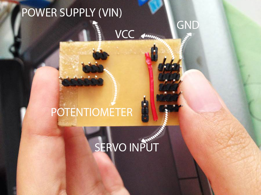
Separated the power supply going to the motor (Vin) than that of the microcontroller (VCC)
Added a jumper that unifies connects both VCC and Vin if wanted to supply them both from the same power supply
Download The Design Files
Code.de
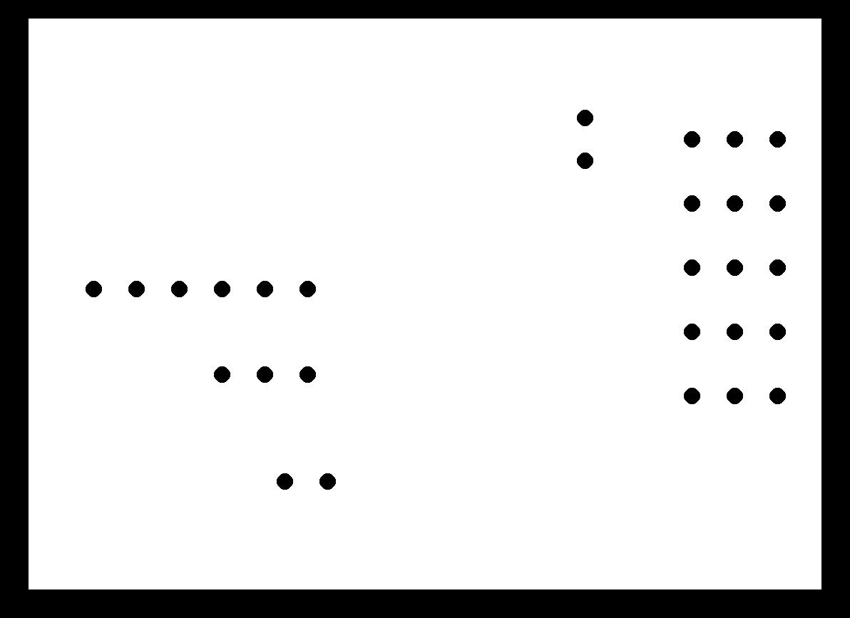
Interior.PNG
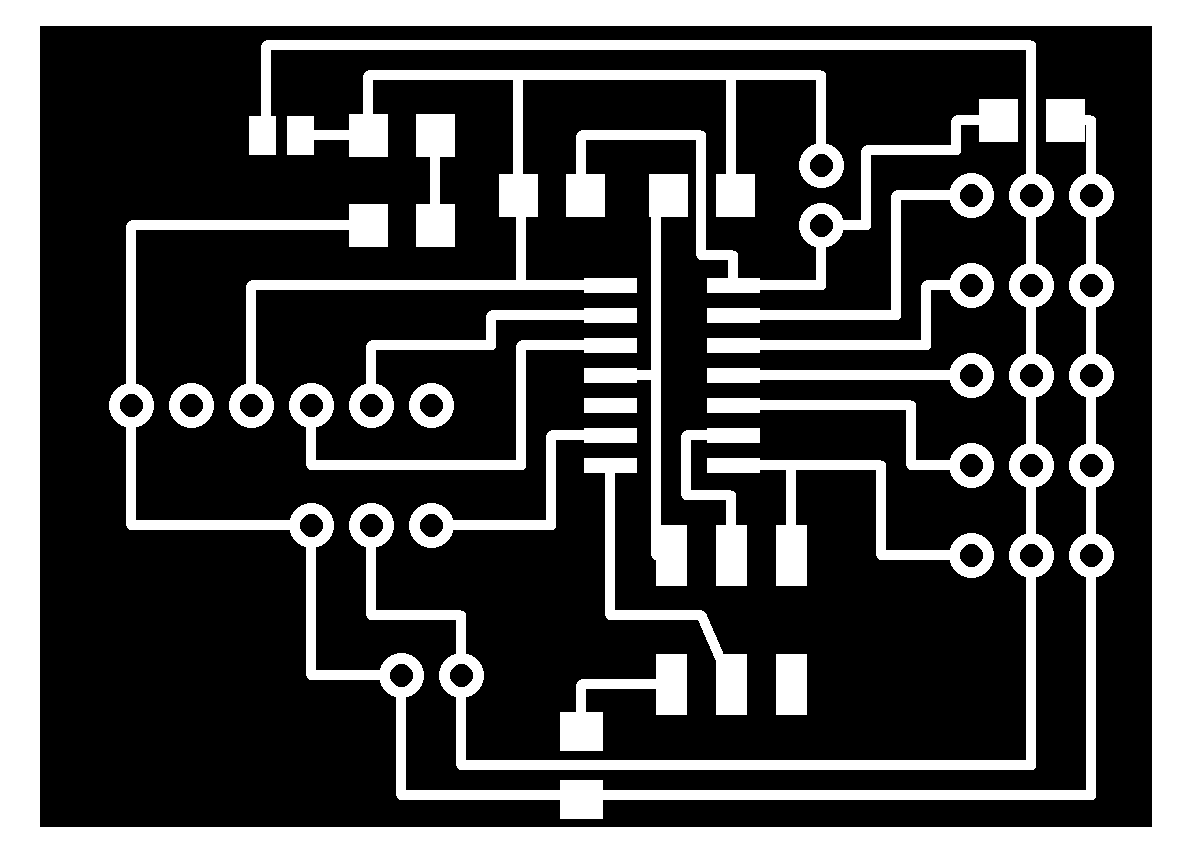
Traces.PNG
Schematic.SCH & Board.BRD
.JPG)