Fab Academy 2014
This week I decided to create another sensor based daughter board and try to take my Embedded Programming assignment a step further. I've been considering and reconsidering my final project, and one idea that keeps coming back is a touchpad with capacitve sensors hidden beneath a thin wooden veneer (which could be laser cut). This could maintain a nice aesthetic, and easily be integrated into any one of the projects I'm considering. So, for this week, in addition to working with my Hall Effect sensor, I decided to create a step response sensor using Neil's hellow world option. This turned out to be more challenging than I had expected. For updates on the Hall Effect sensor including an important reminder about checking to make sure you're not reading a floating pin, see Embedded Programming.
Since I ended up going down a few rabbit holes with the step response sensor, I actually wrote my documentation as quick notes in class. This is actually a much better way of doing things, and hopefully I can continue this going forward. Here was my blow by blow account:
- milling the traces for the board went smoothly. It was a very simple design and milled quickly.
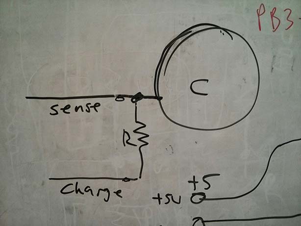
- created the capactive touch sensor board, but thought I had flipped the connectors (brown and red)
- flipped the connectors, and it still didn't work. Eventually figured out that I needed to connect the orange wire instead.
- LESSON - ALWAYS check connections with voltmeter using a continuity test. This would have spared me some grief on the Hall Effect sensor as well.
- tried using this arduino sample sketch.
- got a compiling error that looked like this: /Applications/Arduino.app/Contents/Resources/Java/hardware/tools/avr/bin/../lib/gcc/avr/4.3.2/../../../../avr/lib/avr25/crttn84.o:(.init9+0x2): relocation truncated to fit: R_AVR_13_PCREL against symbol `exit' defined in .fini9 section in /Applications/Arduino.app/Contents/Resources/Java/hardware/tools/avr/bin/../lib/gcc/avr/4.3.2/avr25/libgcc.a(_exit.o)
- Found some user tutorials saying I should update crosspack. Got intimidated and rethought using the example code Neil had provided.
- Tried using Neils example and adopting it by copying and pasting straight into the Arduino IDE.
There was an extra line that I had to delete because there was a variable not declared in the scope (this was something specific to ATTiny)
ADMUX = (0 << REFS2) | (0 << REFS1) | (0 << REFS0) // Vcc ref (Had to remove (0 << REFS2)
I think this is due to the difference in the power pins between the ATTINY 85 and the 45. - Then I needed to change the pins to match the ones used by my header. starting up here:
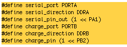
- Next, I had to set the sensor pin here:

see datasheet for details - Then followed AS220's tutorial for setting up Python to work with Neil's python program on my mac. This involved installing pyserial. See the tutorial here.
- At this point, the board worked. Numerous small stumbles along the way, but these were all silly mistakes and the material notes are listed above. Here is the terminal command to get Neil's python program running (make sure you're in the right directory and have checked out what your serial port is, it may not be 'FTGDIDS5'. Refer to the tutorial above for help with this):

- Tested it running through a sheet of veneer, worked, but with much lower shifting in the Python values.
- I also noticed that when I was holding it (and the ground plane was running through my body), I got a much bigger range of inverted values (touching the board caused the values to climb) than when I wasn't holding it.
click for full size 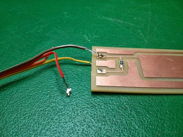
click for full size NOTE FOR NEXT TIME: Shawn advised that I look into the QTouch sensors for multiple button input. These support up to 8 buttons and communicate sort of like a serial connection which would save a lot of pins. Their also developed by ATMEL, so they should integrate nicely with the ATTiny.
- Next, I had to set the sensor pin here: