Design INTERFACE for CNC tooling
The interface is used for creating router bits for 3d milling of semi rigid molds. The idea of make something works at various levels. First it is an interface that design bits that are then printed using 3d printer technology. Second the bit shape and size can now be customize according to ; material density and strength and articulation on surface in order to produce a mold for casting different things. Tooling customization is an effective way to 3d mill conventional and non conventional materials such as; foam, woods and wax, sand, semi soft papers.
Method of work:
- Print test of router bits using a 3d printer
- Develop GH interface with parameters for bit customization
- 3d print of bits
- Test mill- to adjust print setting (mainly density of print)
- Test mill 2 materials ABS and PLA for strength during milling
—Phase 1- proof of concept
Is it possible to mill using a 3d printed bit?
 1
1  2
2
 3
3 4
4
 5
5 6
6
- 3d print of conic bit: Question that raises from this test: If anything is printable! What is the most optimal way to print stronger router bits
- Mill with it – the bit has weaknesses doesn’t resist torque over time.
- Mill result – surface articulation in relation to tool
- Print Generation 1a looked at printing with ABS and PLA ; checking for material strength in relation to print setting, noting limitation in printing and accuracy.
- Sample print of ABS and PLA bits with different print setting
- Print setting to test how print density affect strength of tool
—Phase 2- Milling testing
 1
1 2
2 3
3
4  5
5
6
- Milled pattern; using a base pattern for all milled experiments to allow for precise understanding of what each bit type is capable of producing. The only variable in this experiment is the bit (Variables such as: material, machine setting; tools move speed, and rpm, are with no change.) Noted here are the variation of pattern due to bit variation.
- Bit resistance: here the density of the 3d print is equated to resistance of material to breakage: 2 types of material where used ABS and PLA- shank diameter of ¼” and ½”
- Customization of a tool according too desired result
- ½” Shank dia using PLA has demonstrated exceptional mill qualities.
- Test demonstrate the ability and potential; the former being a programmable purpose of the bit the latter being the erosion rate, which indicate life expectancy. It raises a question in regard to equating a programmable bit that can consume itself at the end of the mill job? After further assessment I opted to disregard this potential due to unpredictability in the erosion rate of the bit and the many factors that affect it; bit material, milled material, feed rate, spindle speed etc….
- Bit size shape to surface articulation is apparent. Noted: tool size can possibly reduce mill time and still maintaining desired result.
—Phase 3- Bit Customization

 1
1
 2
2
 3
3
 4
4
 5
5
- A sample of bit generation with the GH code
- The parameters that affect the bit shape
- Generation of series based on # of fins and top diameter
- From Rhino to Makeware- preparation of files for 3d printing
- Variations of bit shape
—Phase 4- Printable bits
 1
1

2
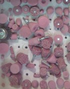
- All generation of bits from concept to proof
- The ability to print more then one bit at the time
Some Notes:
3d printing of bits has demonstrated great potential for the advancement of tool customization specifically to this case, the router bit.
There are more then one direction for this project to continue, as once proven possible the possibilities are in the hand of the designer. As noted earlier many things can be done with those bits, however my primer interest was to create an interface that will aid in the customization of router bits. My main focus in the next phase will be to see how pattern logic can inform bit design.
