Make Something Big
Lesson 9
This week's assignment is to make something BIG. We did not do this assignment alone, but it was a team effort.
This week's assignment is to make something BIG. We did not do this assignment alone, but it was a team effort.
This week’s assignment was to make to something big. We decided to make something really big and work together as a team. The shopbot has a vacuuming installation, which is dusty and loud, so we wanted to make an airtight and sound proof enclosure for this machine. We took the measurements of the room and the machine and put that data into the computer. In our case, we used rhinoceros. The easiest and most obvious solution would have been to make a square enclosure, but we wanted to do it the difficult way and make a curvy wall instead. With the size of the room and position of the machine in mind, we drew several curvy horizontal lines and connected them with the loft function in rhino to make one wall.
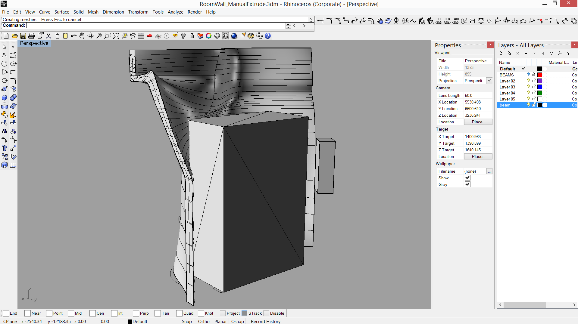 |
There are some beams going overhead and there is one big side beam, which we used as a starting point of the wall. We put these beams in place in rhino and we subtracted the beams from the wall, so we would end up with a perfectly fitting wall.
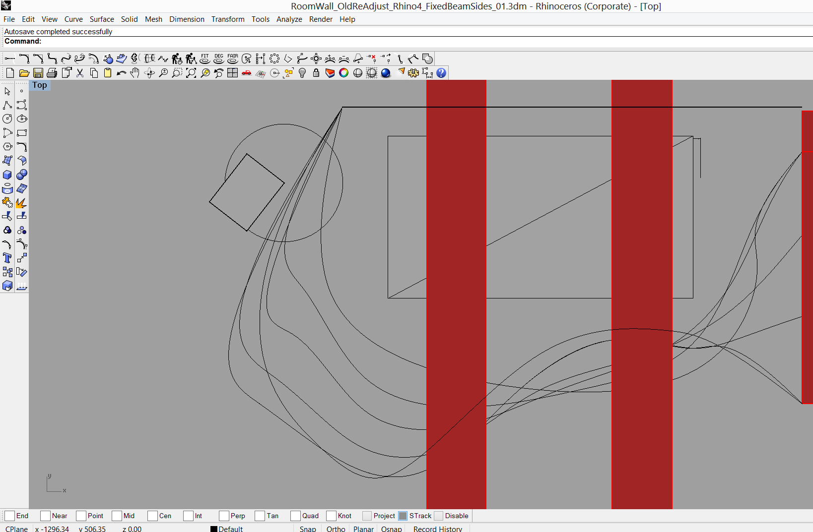 |
We exported this wall file into 123d make, which was used to slice the model into pieces. The file we used was an stl file and we could easily import that into 123d make The program slices the model and make a cut sheet from this model, so it needs some information to do that. It needs to know, if you use inches of mm, the size of the material, thickness of the material and information on the tool diameter. The next step is to set the actual size of the model. In our case we used 3110 mm as height and by using uniform scale the width and length were set automatically. The next step was to choose the way we were going to cut the sheet. For our model we chose interlocked slices. 123d make shows where there are problems with the cut sheet. Our problems were:
We solved the first problem later on in another problem by cutting the 123d make cut sheet into smaller pieces and a puzzle connection pieces, so the parts would click together to make one big piece. In order to keep the wall strong, we decided to change the positions of the “puzzle” pieces, so the wall would not be weak at one horizontal point.
 |
The second problem was relatively easy fixed. The individual parts can be moved around in the model, so they do fit. The third problem was fixed by halving the amount of horizontal and vertical ribs and using a 9mm MDF sheet instead of an 18mm MDF sheet. In addition, we rearranged the parts in such a way that we needed even less sheet. In the end we used 6 sheets of 9mm MDF to make the entire wall. Our wall is curved, so we unfortunately ended up with a lot of excess material. We solved the fourth problem by adding a second line behind the other line, so we would be able to determine the thickness of the wall ourselves.
We exported the cut sheet from 123d make and Michael and Mio added puzzle parts in 123max as we could not get the sheet to imported into illustrator. The file we imported was bigger than worksheet of illustrator. As we cut the parts into smaller pieces, we could more easily arrange the parts and that saved a lot space and thus material.
 |
We made two smaller models to see, if the model would stand on its own and if everything would fit. We cut one out in cardboard and one in wood. As you can see, the smaller models have more ribs than the end model.
 |
 |
We fixed the MDF sheet to the shopbot and set the XYZ direction of the machine, so it would stay within the material and it would not hit any of the screws that would hold the material in place. We used a 3mm and set the size of the material and its position. The next step was to add dog bones to all the snap fit connections. In some of the sheets there were some issues with the model’s connection to the puzzle pieces. This could be mended in the partwork’s software. We set the cutting depth to 10mm as the machine has to go through the 9mm MDF plate. The next step was to make and save a toolpath and see if the machine would follow the correct path in the material. The material is 9mm thick, but we found out that at some places it did not cut through even if we used 10mm cutting depth. We changed the measuring position of the Z direction to a place more in the center of the board and changed the cutting depth to 11mm and this solved the problem of partially cut sheets. We had spend a lot of time on designing the model and we had to change it several times, so we did not have much time on the shopbot left. We worked together efficiently, so we would work as a well oiled machine to get everything done on time.
 |
When we put everything together and then we encountered some problems:
We solved the first problem by widening the snap fit by hand. We should have used an offset to make the snap fit a little bit wider. We wanted to make a test run, but were short on time. The second problem we solved by sawing the wall by hand, so it would fit. The third problem we will solve by putting supports on the parts that have been broken.
 |
The wall will need a door and at the back of the wall, there is a breaker box, which was not reachable as the wall was scaled to big. We decided to cut the end of the wall to enable easy access to the breaker box. We were already aware of the issues with the breaker box before we started cutting, but we could not solve it within the software. The door will be added later and we are thinking of adding supports at the place where the door is going to be.
Individual things done:
The first step was to measure the exact dimensions of the wall around the vacuum machine and put these data into the computer. These dimensions were relatively straigthforward, but the 3d model had to be modelled around a standing beam. We needed to know the exact dimension and we concluded that we needed a 3d model of the beam to accurately model the wall around this beam. My task was to design this beam in a 3d model, so Rick and Michael could use this to model the wall around.
We tried different models to make a waving wall. Rick, Michael and Mio were better at 3d design in Rhino. I tried to make a wall in sketchup and R statistics, but we choose to use the model from Rick and Michael as the Rhino has a nice feature which can combine lines into wall.
Next we made some scale models of the designs, made by Rick and Michael, and me and Rein cut them out on the laser and put them together.
When Michael and Rick were designing the cut sheets for the shopbot, me and Mio started to cut out the cut sheets. We split the work in half, so Mio and me did half the work. Michael numbered the cut outs, so we could easily put them together. Rick and Rein were cleaning the cut out parts and started putting them together. When we finished the cutting of the plates, we joined them and also helped putting the model together.