Electronics Design
Lesson 6
This week's assignment is to redraw the "echo hello-world board" and add at least a button and a LED (with current-limiting resistor), check the design rules and than make the board.
This week's assignment is to redraw the "echo hello-world board" and add at least a button and a LED (with current-limiting resistor), check the design rules and than make the board.
Before we started to change the board, we downloaded eagle and added the fablab library in the eagle/lbr directory. The next step was to create a new project and add new parts to the schematic while looking at the example given to us. You can add parts by typing add in the bar above the schematic or click on the logo as indicated below.
 |
The next step was to the power (VCC and GND) to the all the components, so that the components can function. VCC is + and GND is -.
 |
After this has been done, we add the rest of the connections between the components and between the IC and the components. We can name lines, so we can refer to them and this prevents cluttering of the design. Look at RESET in the picture below. These lines are not connected in the schematic, but they will be when we go the board design
 |
Click and generate/switch to board button and a new window will open. In this window the parts are shown in their real size and the yellow lines are their connections. Arrange the parts by clicking on the white cross once and then move them to the place you want it to be.
 |
The next step is to click on the ends of the parts and when a red line appears drag it to the part where the yellow lines points to. The red line will snap to the grid. This might cause a problem, as you might need a smaller step. You can change the grid or use ALT and then move the red line.
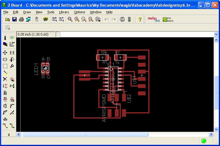 |
The next step is to make the area marked by the white line smaller, as this will indicate the size of the board.
 |
The next step is to add our own components, namely the button and the led light.
 |
To check the board for failures, you have to go to the DRC button (design rule check) and eagle will check if the lines are not too close together. If they are, this should be corrected or else you can go to next step. The last part is to add a layer which is invisible, but bigger than the board. This will be the area that will be cut by the milling machine. This picture will be exported in png format and edited in the gimp or illustrator. The image has to be separated in two pictures. One with only the copper milling parts and one with only the exterior which will be the cut out of the entire board.
 |
 |
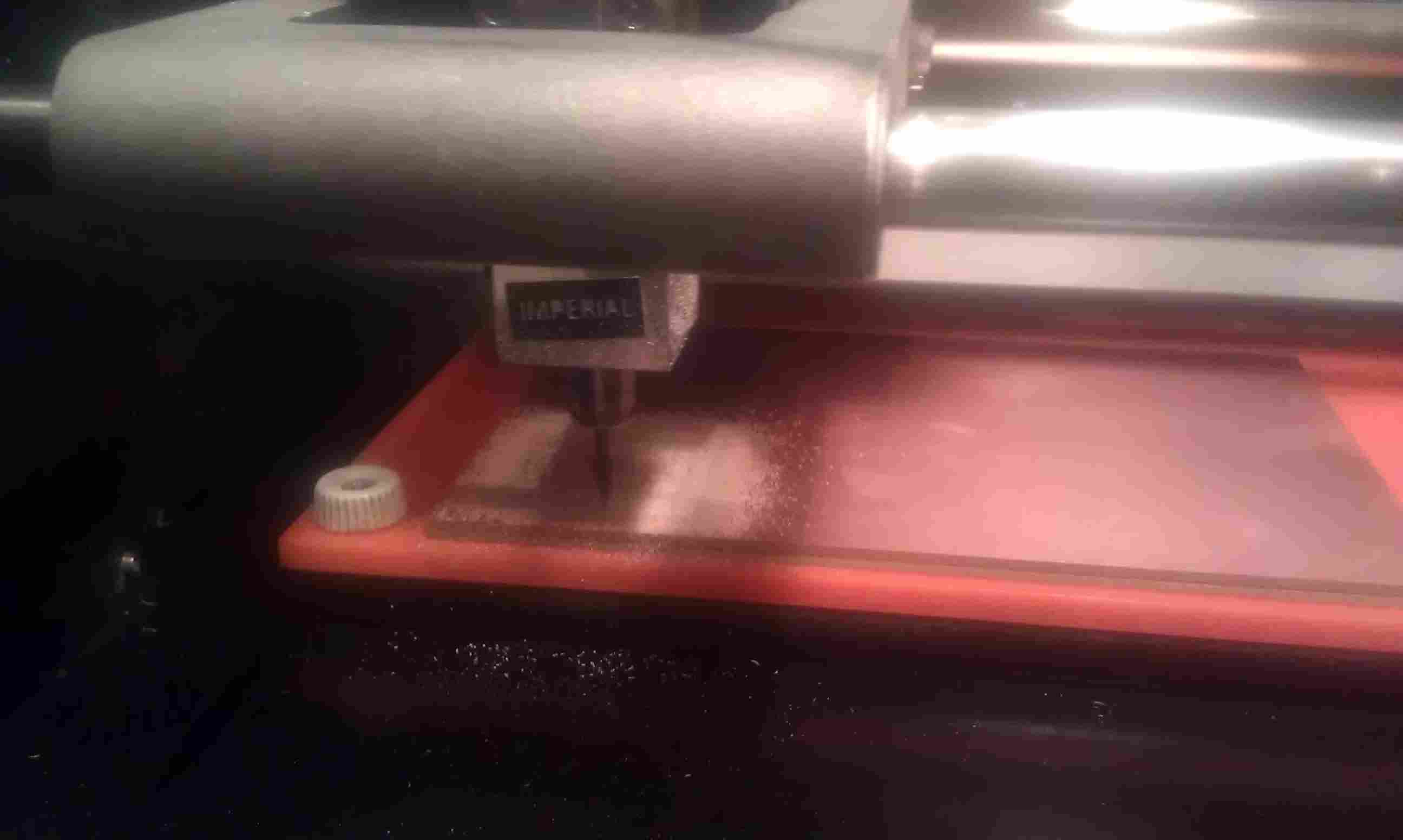
Milling the board is the same as in the electronics production. The png file has to be converted to a rml file for the milling machine to read. For the copper milling, the machine has to be set to 1/64 setting and you have to set the appropriate mill. Make the board and then load the other png file with the cut out of the board. Set the settings to 1/32 and use the appropriate mill 1/32 to cut the board.
 |
 |
The last part is to solder all the components on the board.
 |