Computer controled cutting
Lesson 3
This week's assignment is to make a press-fit model with a laser cutter and make sticker with the vinyl cutter.
This week's assignment is to make a press-fit model with a laser cutter and make sticker with the vinyl cutter.
I have little experience with illustrator or inkscape, so i was happy just to learn the basics of these programs for now to be able to get a text print out for the vinyl cutter. For my final project i am working on a hydroponics system in the form of a cube, so i came up with the name:HYDROCUBE for my system. I wanted to print this, so i might use it later in the project. I wrote the text:HYDROCUBE in illustrator and i drew a rectangle around it. I outlined the text, so it would cut around the text. I set the stroke thickness at less than 0,001mm, so it would be less than the thickness of the cutting knife. I took a piece of vinyl and put in the machine. The wheels indicated where the cutting will be. I cleaned the knife and set it, so it would stick out just a little. I put the knife back and tightened it in the machine. I let the machine measure the width and length of the piece, set the pressure at 160 and the cutting speed at 20. I did a test and noticed the knife was not cutting deep enough. I reset the knife and did the test again. This time the knife went through the vinyl. I set the origin away from the test cutting, transferred the dimensions of the piece of vinyl into illustrator and changed the position of the cutting on the screen. Next, i pressed on print and the printer started cutting the vinyl. It started cutting on another place than i expected, but it did do the cutting correctly. Although i could get vinyl from the support material, it was quite a struggle to get everything off without damaging it. I noticed that, at some points, it looked as if it did not cut the vinyl completely. The end result of the cutting, you can see below.
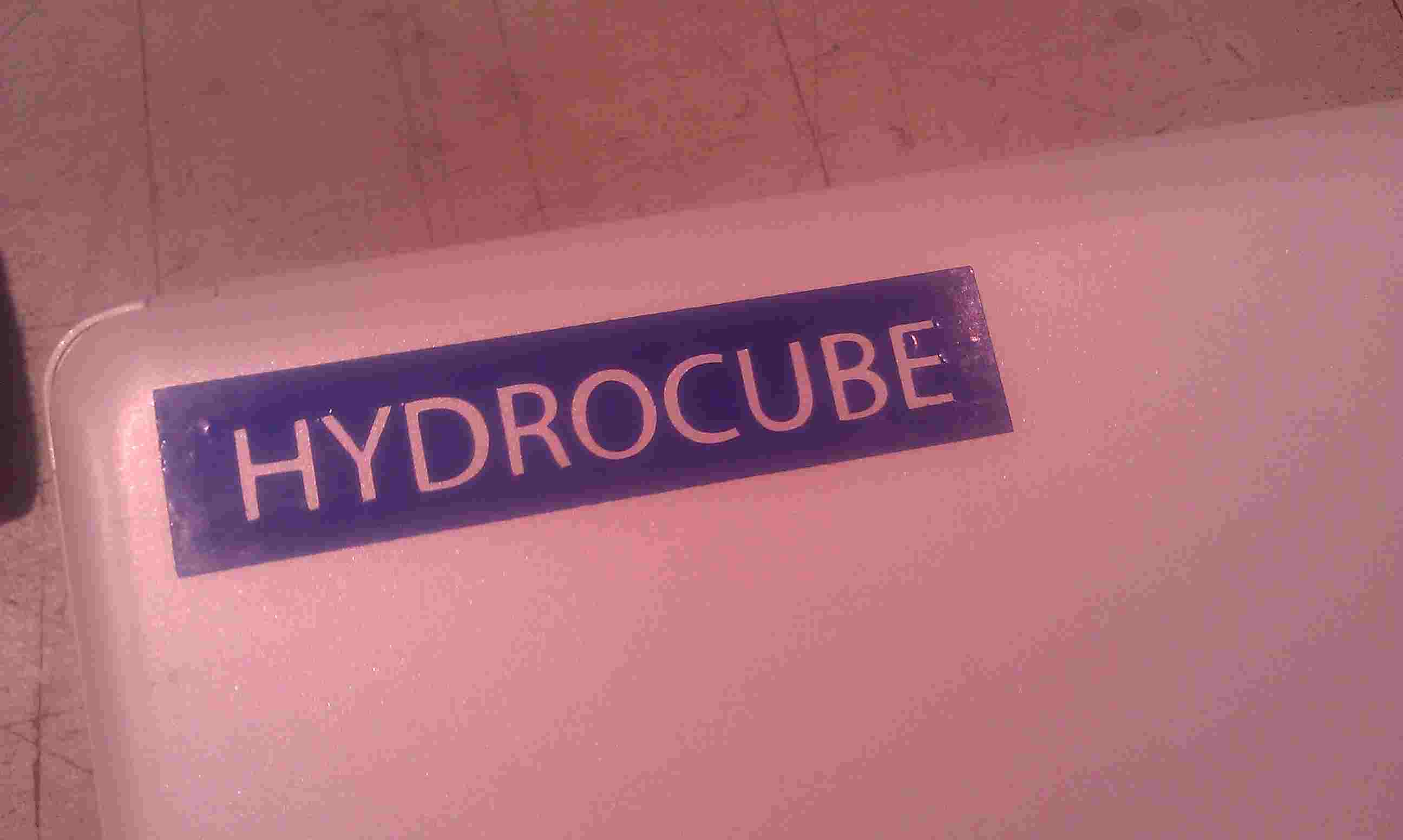 |
I started making the press-fit in inkscape, but i quickly found that it was quite a struggle for me to get all the dimensions right. I started looking at openscad and found it easier for me to work. I am used to java programming and the parametric approach really suits me. I learned the basics in an afternoon and at the end of the day, i was able to make quick press-fit models and change their dimensions in a heartbeat. My cutting material of choice is MDF 3mm, so i knew the approximate slot opening of the press-fit, should be around this dimension. I decided to make a test model having varying opening dimensions to find out which has the best fit.
The model below is created in openscad with 5 slots starting from 3.2mm going down to 2.8mm
 |
 |
openscad code:
c_radius= 30; // size of the circle (times 2)
s_length= c_radius*0.5; // level where slot ends
s_width=0.1; // testing for size
setter= 4.7; // adjusting width manually
width= (s_length/2)-(1*s_width)-(setter);
space= 2*c_radius*0.1; // space between the cuttings
echo("width:", width);
echo("space:", space);
module circlefab2()
{
difference(){
circle(c_radius);
for(r=[0:5])
{
rotate([0,0,r*360/5]) translate([c_radius-((s_length/2)),0,0]) {
union(){
translate([(s_length/2)+(setter),0,0]) rotate(a=45, v=[0,0,1]) square(s_length,center = true);
square([s_length-(r*s_width),(s_length/2)-(r*s_width)-(setter)],center = true);
}
}
}
}
}
module circlefab3(){
translate([c_radius+1,c_radius+1,0]) circlefab2();
}
After laser cutting the two press-fit above. I found out that 2.8mm is the best fitting slot size for the press kit.
I transferred that slot information to my production set and reproduced that particular press-fit model 20 times (6 * 5 times). The code (and its image) for reproducing this press-fit you can find below.
 |
 |
openscad code:
c_radius= 30; // size of the circle (times 2)
s_length= c_radius*0.5; // level where slot ends
s_width=0.0; // testing for size
setter= 4.7; // adjusting width manually
width= (s_length/2)-(1*s_width)-(setter);
space= 2*c_radius*0.1; // space between the cuttings
echo("width:", width);
echo("space:", space);
module circlefab2()
{
difference(){
circle(c_radius);
for(r=[0:5])
{
rotate([0,0,r*360/5]) translate([c_radius-((s_length/2)),0,0]) {
union(){
translate([(s_length/2)+(setter),0,0]) rotate(a=45, v=[0,0,1]) square(s_length,center = true);
square([s_length-(r*s_width),(s_length/2)-(r*s_width)-(setter)],center = true);
}
}
}
}
}
module circlefab3(){
translate([c_radius+1,c_radius+1,0]) circlefab2();
}
for(x=[0:4]){
for(y=[0:5]){
translate([(x*2*c_radius*1.1),(y*2*c_radius*1.1),0]) circlefab3();
}
}
Laser cutting process
When i loaded my openscad model into illustrator, there were some unexpected issues with recognition of my model in dxf format. I had to select the entire model, click to set to path and then combine, so the computer knew which path to follow when it cut the model. I changed the line color to RGB red and its line thickness to 0,001mm and then i adjusted the laser cutting setting for the red color to cut MDF 3mm (1.6 speed, 100 power and 400 dpi.) Furthermore, i used relative printing, so i needed to use autofocus to choose my starting point. I turned on the air fan, closed the cover, send the print to the laser cutter. Checked if everything was ok and then the laser started cutting the press-fit pieces from the board.
I had some unexpected issues, which did not result in a perfect end result. I noticed after cut my press-fits in the laser, that my MDF board was slightly bend and that the laser cutter did not cut through all the material in the part where the board was bend. Also the quality of the cutting deteriorated when it was further removed from its origin.
Below, you can see the end result.
 |