Assignment : measure something
Using Machinery :
- Modela MDX-20
- Solder Set
- Glue Gun
Using software :
- Eagle
- Arduino IDE
Switch
At the beginning, I failed to make circuit board.
Because my design was incorrect.
My failed design
Next I used Neil's design. because I didn't have a time to design.
But I also failed milling .
I used "fabmodule" milling curcuit.
I executed command "make rml" before "moving x and y" command.
I had to execute "make rml" after "moving x and y".
So I couldn't make the board first.
As I didn't have a board, I tried to use the board which I made "electric design" assignment.
For using "hello button 45.c " and make file, I changed their files about below.
	---hello.button.45.c---

	#define input_pin(1 << PB4) > (1 << PB2)

	#define serial_port PORTB > PORTA

	#define serial_direction DDRB > DDRA

	#define serial_pin_out (1 << PB2) > (1 << PA1)


	---hello.button.make---

	PROJECT = hello.button.44 > hello.button.45

	MMCU = attiny45 > attiny44

	F_CPU = 8000000 > 20000000

	And I change all "a44" words to "t45"
Button sensor was working. I checked using the Arduino IDE serial monitor.
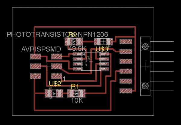
Light Sensor
Then I also tried to make a lighting sensor and a step response sensor.
First, I made lighting sensor.
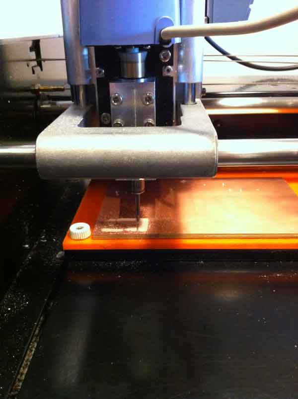
I set copper sheet to the Modela.
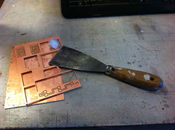
I milled the board and solder.
I connected my computer to the sensor board.
Then the ATTiny45 was burned with smoke.
That's why the ATTiny45's direction was incorrect on the board.
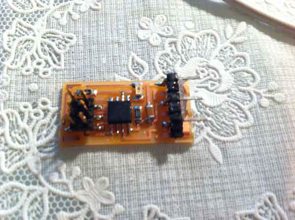
I changed it and fixed direction, the sensor was working.
Step Response
Next I made a step response sensor.
I could mill and solder perfectly.
But This board was fixed with glue.
So when I connected my computer, and pulled out, header pin were dislocated the board.
And some copper sheet also dislocated from the board.
So I had to solder using connector again.
And My circuit board was messy, that's why some copper sheet were dislocated.
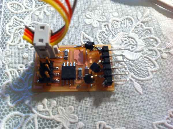
This sensor was working.