Week 16 Final Project
I can summarise my progress towards my final project by assembling the steps I made as the course progressed...
Week 1: FabLab Project
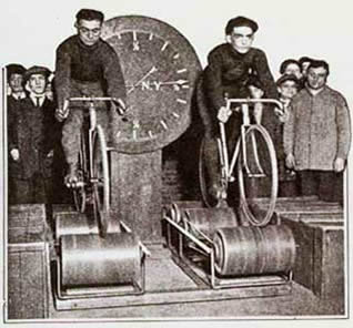
My FabLab project will be the design and manufacture of a cycle trainer with virtual reality capabilities. I am a keen cyclist and in the winter in the UK it is often too cold and dark to go cycling outside in safety. For many years cyclists have trained in the winter on rollers and turbo trainers (resistance devices connected to the rear wheel of a static bike). There has even, in the past, been a branch of cycle sport devoted to racing on rollers.Two or more bikes were placed on rollers side by side, and the rollers are connected to a timing system. Roller racing was popular in 1950s Britain, often preceding films at the cinema or taking place in between dances at dance halls.
I want to make a modern roller trainer with which it will be possible to train or race with other riders connected via the internet. This is a product that I want and which I am sure is of interest to other riders keen to alleviate the tedium of winter training.
The design and manufacture of my cycle trainer will also require me to acquire the skills being taught in the FabLab. I will need to produce a design on CAD. Large frame components will be CNC machined. Smaller components will be moulded or 3D printed. I will need to develop and make a wireless device to pick up wheel speed, cadence and power data from my bike. I will need to develop software and interfaces to allow virtual interaction over the internet. I believe this to be challenging but ultimately achievable.
Week 2: Computer-aided design
SketchUp
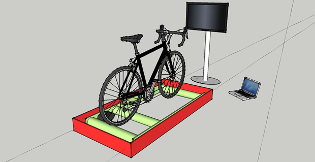
I decided to use the freely available SketchUp program to generate concept drawings of my cycling rollers project. The basic tutorials for SketchUp are easy to follow and provide all the tools needed to produce a basic drawing. SketchUp is good for quick free drawing in 3D. It has an extensive library of building and interior design elements available for import from its warehouse. In my view, it is biased towards architectural design. I am not sure how easy the surface and line generated elements will be to use for a complex engineered assembly.
Week 6: Electronics design
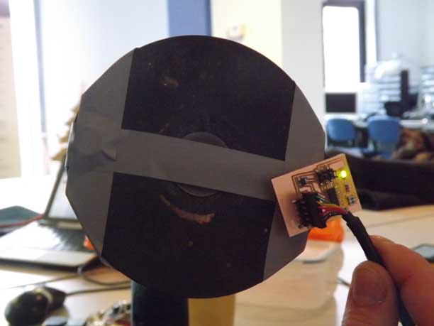
My final project, cycling rollers, requires a method of sensing the rotational speed of one of the rollers. Typically speed sensors on cycles work by detecting the passing of a magnet attached to a spoke on one of the wheels using a Hall Effect sensor or a reed switch. I intend to use a similar principle to determine the “road” speed of the rollers by placing a magnet on one of the rollers and counting the number of rotations in a known time. As an initial step towards this, I want to establish that I can use a Hall sensor in this way by having it illuminate an LED as it passes. This feature will be incorporated in the final design to allow a user to determine the speed sensing is operational and will allow me to start developing with the Attiny44.
Hall Effect sensor
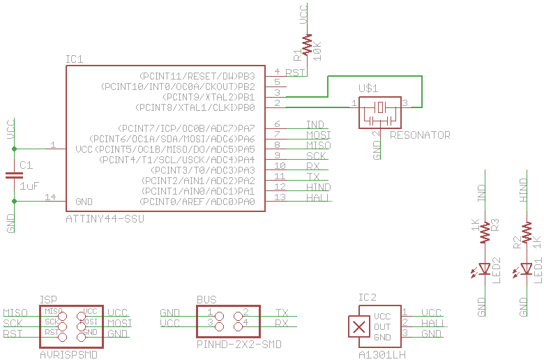
I reviewed the data sheet for the Allegro A130x series of Hall sensors in the FabLab inventory and determined they were suitable for my need. One feature of their operation was the output signal was centred on Vcc/2 swinging up to Vcc and down to Gnd depending on the polarity of the magnet passing the sensor. This meant that I needed to use an Analogue to Digital Convertor on the Attiny44 to read the input signal which in turn determined that a bit on Port A would be required for the input signal. I reviewed the data sheets for the Hall sensor and the Attiny44 and determined no further external circuitry was needed to connect the two devices.
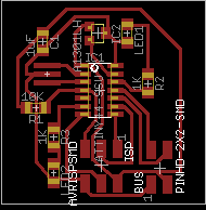
Circuit board design
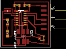
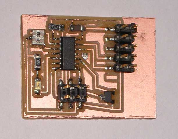
Having become familiar with Eagle following the tutorials on Sparkfun, I drew the schematic for my circuit. Once I had inputted that, I used the auto-routing feature to layout the board traces. I found that I could eliminate the need for any jumpers by utilising a combination of Port A pins which I finally selected. I cut the PCB using the Modella and mounted the components on the board. I found the resonator particularly difficult to mount as I could not be sure solder had flowed underneath it. I managed to lift a copper track through overheating the board whilst doing this, although it was not broken and did not need repairing. Mechanically it is held in place as the resonator has 3 contacts holding it in position.
Programming the ATtiny44
Once the board was checked I programmed it using the FabISP. My programming experience is limited so I elected to use the Arduino compiler to ease this process. As a test, I first programmed the controller to blink the LED on and off every second.
The next step was to establish the controller was reading the Hall Effect sensor by reading the ADC output in a serial data stream sent to my computer. This was successful and showed a stream of readings averaging 512 corresponding to Vcc/2 as expected, changing when a magnet was passed near the sensor.
Finally I added some logic which illuminated the LED when the sensor reading crosses upper or lower thresholds indicating the proximity of a magnet of either polarity. This operated successfully.
Week 8: Embedded programming
In this week’s task I carried out further development of the speed sensor I need for my final project – to build training/racing cycle rollers. I built on the simple program I loaded in to my speed sensor circuit at the time that I built it in the electronics design week.
For the final project, the embedded program needs to count the number of rotations of the roller per second and send the result to a lap top for display and further processing by the laptop’s software.
Given my lack of knowledge of programming languages, I decided to continue using the Arduino development environment to allow me to learn basic coding principles. The two key components to develop were to find a way of incrementing a counter once when the magnet passes the Hall sensor and counting the number of times this happens in one second. The Arduino examples library includes a sketch which shows how to perform edge detection. This formed the basis for my using a variable to detect the state of the Hall sensor and how it compares to the state it was in, the last time the program looped. If it has changed from LOW to HIGH, i.e. if a leading edge is detected, a counter is incremented.
Once I had worked out this function, I needed to find a way of counting the number of edges occurring in one second and then re-setting the counter for the next second’s count. I designed a loop timer using the number of milliseconds the program has been running since starting and added 1000ms to set an end point for a loop. Originally I tried to use an “if” statement to try to control the loop. However, a “while” loop was actually needed so as to allow the loop to keep re-running until the second has ended. Once I understood this properly, I nested the edge detection code within a loop that counts for one second. At the end of one second the current pulse count is “printed” to the serial port and then the timer and counter are reset.
The program was compiled successfully and loaded on to the chip using the Attiny44 interface in the Arduino IDE. It was possible to see the count written to the serial port using Arduino’s serial monitor. Pulse counting was then successfully tested up to 15 pulses per second using 2 magnets attached to a disc rotated by an electric drill at up to 500 rpm.
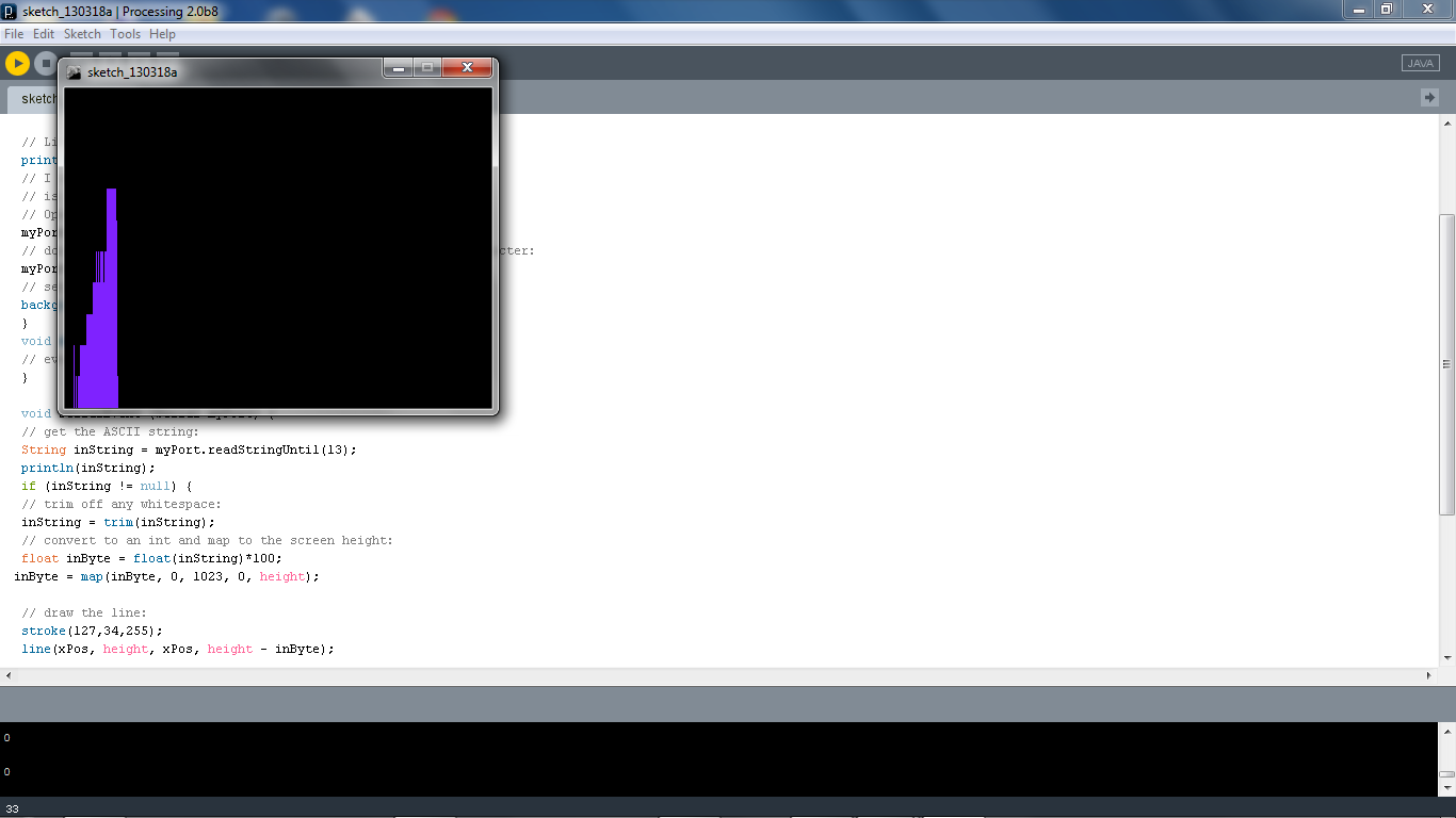
The next stage of the development was to display the pulse count graphically on my lap top. A proof of principle was achieved using Processing graphical display software based on an example in the Arduino library. The software displays a basic bar chart of each second’s reading.
Week 9:Computer controlled machining
This week I wanted to make the inner frame of the cycle trainer/racing rollers machine for my final project.
This frame needs to bear and position accurately 3 rollers which will support the rider and bike plus the speed sensor and device to create resistance on one of the rollers. To achieve this it needs to be stiff, strong enough to support up to 250dN [3* (bike +rider)] of shock loads and be sufficiently accurately built to allow the rollers to be aligned correctly across the frame. I selected 12mm ply for the frame material as I believe it has the correct lateral strength for the load bearing, would be sufficiently stiff when braced, durable and not too heavy.
 My first task was to complete the conceptual arrangement of the design. I started this in FreeCAD earlier in the course. Whilst the basic elements had been drawn, I now needed to ensure the parts were accurately dimensioned and to add stiffening structural elements.
The next requirement was to add details of the joints. I experimented with adding finger joints in FreeCAD. I found it difficult to make quick progress without creating tremendously complex drawing components comprising many small joint elements. I was also concerned about exporting the results to the ShopBot. I tried exporting one part as an *.stl file and reading it into SketchUp and found I could not see the result. These concerns about detailing the design in FreeCAD prompted me to produce the cutting paths outlines in another software package.
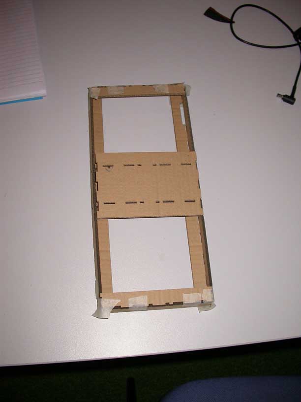
The detailed cutting paths were made in Inkscape. It was particularly important to check the detailed parts for fit as they were not derived directly from the 3D arrangement; rather they were re-drawn in 2D. I scaled the large design down by a factor of 5 and cut it in cardboard on the laser cutter. The first scale model highlighted 2 errors in placement of joints which I corrected. Joel also advised me to reduce the number of fingers in the long joints to aid assembly. I cut a second scale model and found the new design to be correct.
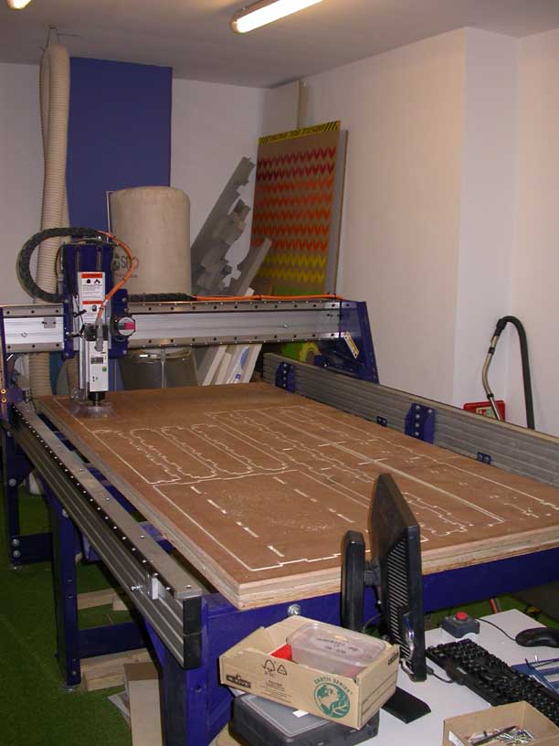
The Inkscape files were translated to *.dxf for the ShopBot and I added fillets and prepared the files for cutting. A sheet of 12mm apply was fixed in place and cut. Two problems became immediately apparent. The plywood sheet was warped when freestanding. Although we attempted to eliminate this when fixing to the ShopBot, in the cutting process the restraint provided by the fixing screws diminished as the cutting progressed. This caused many of the cuts not to be deep enough despite the programmed cut depth being theoretically sufficient. Secondly the design of the finger joints is problematic. The build up of tolerances over 1.7m length is leading the joints to be misaligned. This could be a result of designing each part separately in Inkscape and not using exploded parts from a unified 3D design and/or general tolerance build up.
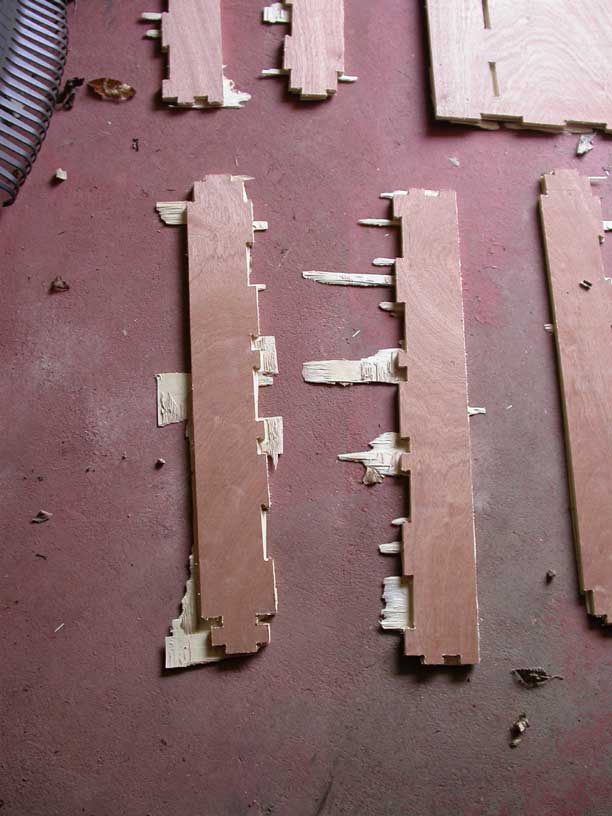
As a result the construction of the frame is not complete yet. My next step is to redraw the detailed designing SketchUp in 3D and then explode the parts – a technique Joel has shown me. I will modify the finger joints on the long joined edges and create test pieces before committing to the final cut. I will also create fixture points in the cutting path layout to restrain the pieces more effectively in cutting.
Update 09/04/13
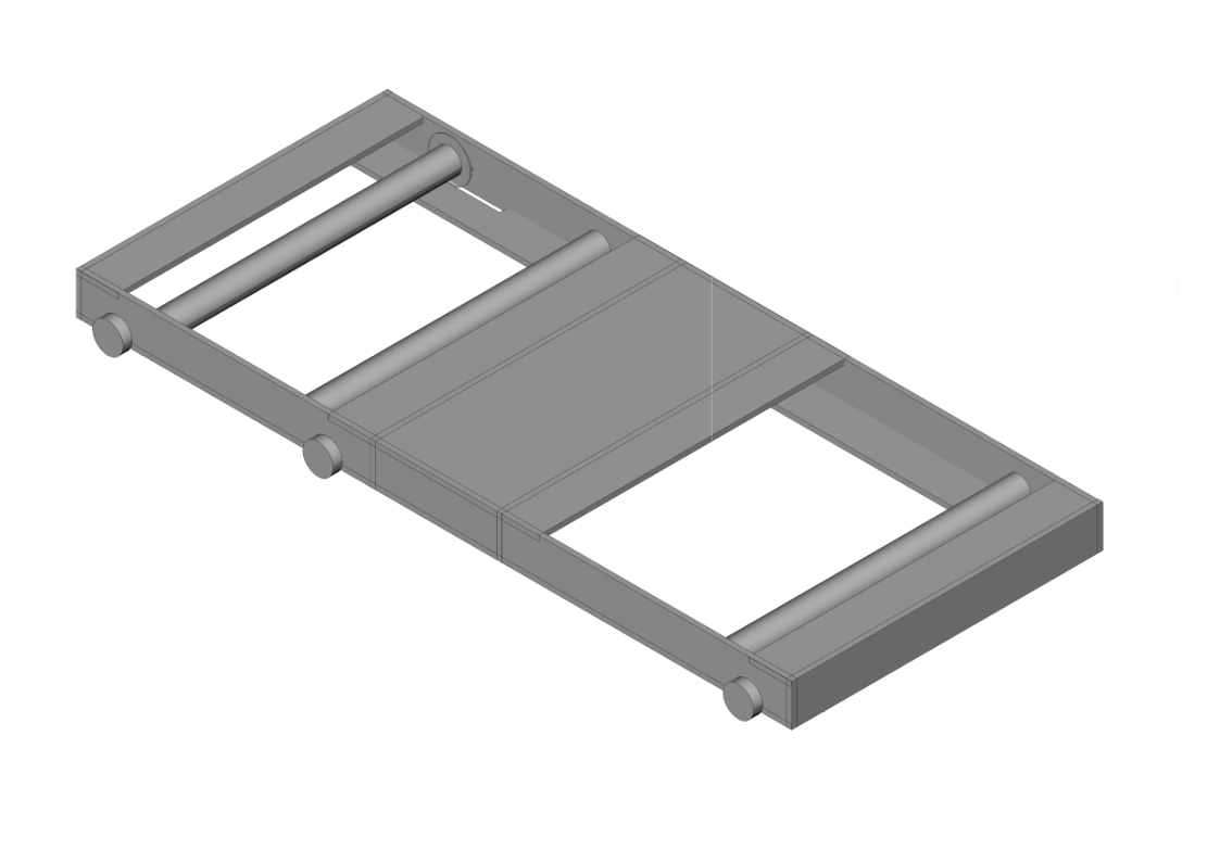
The rollers frame was re-designed to be simpler and to have less jointed lengths. I also completed the whole design by including the rails and wheels to allow the roller carriage to move backwards and forwards.
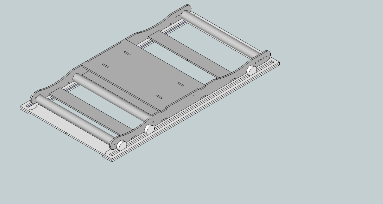
I used SketchUp to complete the design. Once the 3D assembly was designed, I copied the surface shapes I needed to cut on to a 1220*2440mm surface to be cut on the ShopBot. I also ensured there were sufficient sites on the cutting sheet to fix it properly to the ShopBot bed in order to prevent the poor cutting experienced in the first attempt.
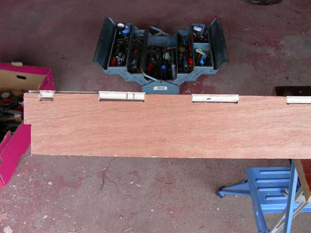
Several tool paths were designed in Partworks with 2 drilling paths needed for the fixturing holes and another for some 6mm holes which were part of the design, in addition to the end mill paths for inner and outer surfaces. The resulting cut quality was vastly improved despite the plywood used being very warped.
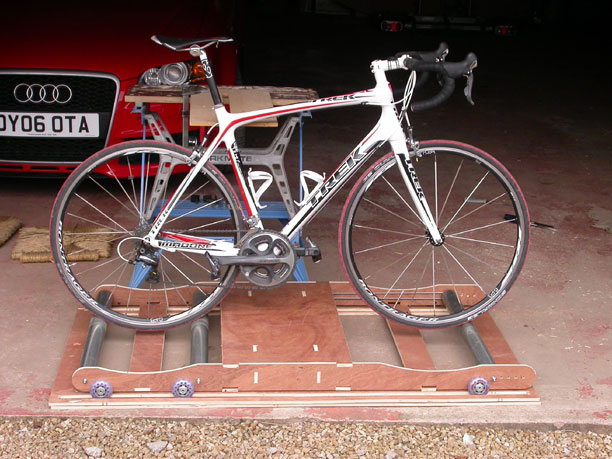
Most of the joints needed to be cleaned and eased by hand, but assembly was straight forward.
Update 22/05/13
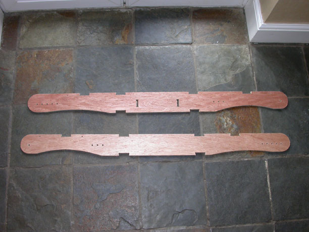
I modified the rollers spacings to improve the support for the bike and to allow the drive band for the front roller to operate at the correct tension. The front roller was positioned too far away from the middle roller. I did this using a hand drill making holes at 25mm intervals and experimenting until I found a satisfactory arrangement.
Once I had this, I modified my original SketchUp design and recut the side plates on the ShopBot. I need to cut two further cross stretchers as they now need to be modified.
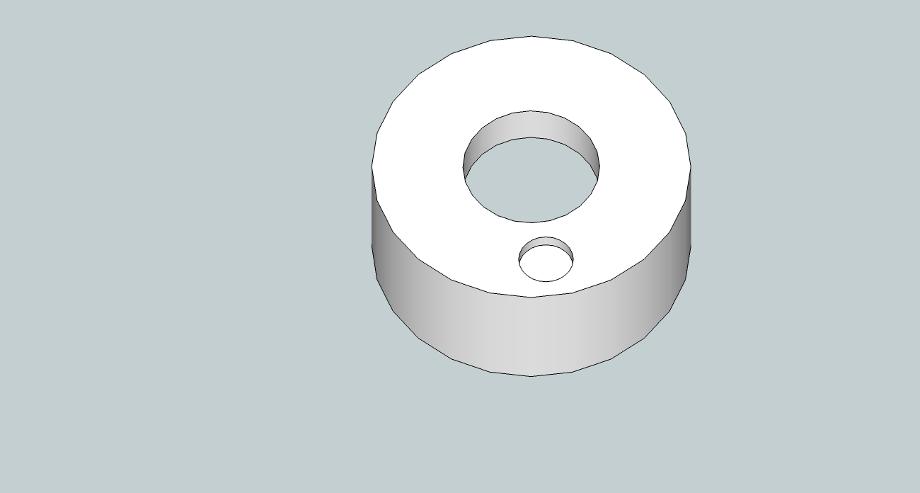
I also designed a carrier which will sit on the rear roller for the magnet needed for the Hall sensor to detect the speed of rotation. I produced an stl file which is awaiting the 3D printer.
Next steps are to re-assemble the modified design and mount the circuit board and magnet. Further work is also required to improve the Processing sketch which measures progress in the race.
Week12: Interface and Application Programming
For this week’s task I started to build the user interface for the cycling training/racing rollers I will be building for my final project. I am aiming to measure the distance covered and the speed of two riders competing and compare them in a computer application to determine a winner. I have already developed a speed measuring sensor based on the hall sensor in the input devices week.
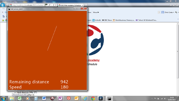
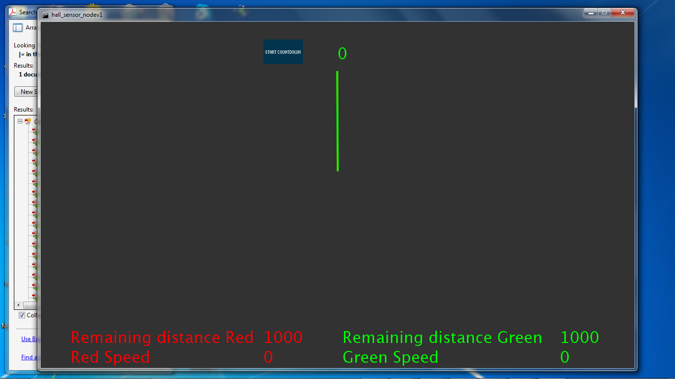
I used Processing to develop the graphics. I want to include a clock which counts down the racing distance with a numerical indication of distance and speed. I found an example which illustrated how to draw a circle using Processing. I modified this to position the end point of a line, the other end of which is a fixed point. Progress towards the finishing distance is factored over the circumference of a circle and the end of the line is progressively moves producing the effect of a clock hand moving. A count down of distance to the end point of the race is added in text form alongside an instantaneous reading of speed.
The hall sensor circuit produces a count of revolutions as measured by the passing of a magnet each second. The count is written as an ASCII string to the serial port. I modified an example routine to read in a string and make it in to an integer, which is deducted from the race distance very second. This controls the position of the clock hand and is displayed on the distance counter. Speed is calculated by multiplying the revolutions per minute count by 60.The Sketch works well when tested with a magnet mounted on a drill.
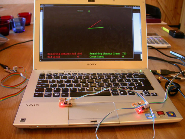
Next I wanted to explore the possibility of the graphics comparing the distance and speeds of two remote riders connected via the internet. This requires the application to be based on the web and to receive data via two (or more) computer’s serial ports. Processing has a java script mode so I used this to export the processing script to an html page. The next stage is to connect the html with serial data inputs. I am still currently working on this.
There are two avenues I am exploring. Seriality is a browser plug in which is being developed to allow interaction between physical devices and certain web browsers. I am also looking at developing a Chrome app. Chrome apps offer the possibility of being connected to usb, serial or bluetooth devices.
Week 14: Communications
My final project, a roller racing system for cycles, needs a small network to start a race timer, poll the speeds of two competing cyclists and to display the results. So, this week I designed the network to execute this.
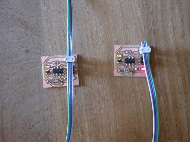
My first step was to add a serial bus and an additional indicator LED for communications activity to the Hall sensor detector I made in previous weeks. I designed this using Eagle. I then made two circuit boards, one for each racer in the network. I also made a bridge circuit from the hello. bus. bridge design. I mistakenly thought that the bridge circuit was needed to interact with the nodes. On closer examination I found that the bridge is simply a node with a FTDI header, but with no difference in code.
I needed to complete two pieces of coding. The nodes’ program needs to detect the passing of a magnet using edge detection, count the number of detections in a second and transmit them with a node identifier. A Processing sketch needs to countdown a race start, communicate to the nodes that the races has started, decode the messages from the nodes and display the results.
The coding is still in progress. I have a functioning Processing sketch which I believe is working correctly. I am currently fault finding the C code for the nodes. They are successfully detecting and transmitting data. As I wrote the code for the previous implementation of the Hall sensor using the Arduino IDE, I wanted to use C this time and use the hardware timers on the Attiny44 rather than software. Thus, I am becoming familiar with interrupt routines and at the time of writing have designed a simple one which flashes a LED. Next steps will be to use this to transmit race data each second and then finally to ensure that the node receives data from the Processing sketch correctly.
Update 8/5/13
A timer interrupt routine was successfully coded to send count data for the number of passes of the magnet each second. The next challenge involved combining this information with a node indentifier and transmitting the data. This is also working well now. The final step was to deocde the transmissions in the Processing sketch. I need to decode the transmitted string characted by character in order to identify and decode the speed data. This has now been executed. Some more work is needed to improve the count down and accuracy of the Processing sketch but effective communication between the nodes and the hub software has now been established.
Update 28/05/13: Final project completion
One of new side pieces which I cut for the roller’s frames broke or when I was attempting to re-assemble the structure. The interference fit on the joints was too heavy and the part split. Given the time constraints and the fact that the previous set of side pieces was functional, I decided to assemble the frame with them. All the pieces went together well.
I re-designed the magnet holder to require less material thus reducing its printing cost. This fitted well over the end of rear roller. The recess for the magnet was eased a little with a file to allow the magnet to sit in the holder. The only other addition to the design was two rubber belts on the driven rollers to guide the main drive band and stop it falling off its rollers.
On initial testing the design works well. The structure is rigid and the rollers run true. The rollers present more resistance to turning than originally expected which may be due to their being specified as heavy duty – a choice I made to ensure they were sufficiently robust. The roller carriage moves well on its tracks. It is restrained by two elastic bungee cords to absorb changes in momentum as the rider moves backwards and forwards on the bike. Overall the unit functions well.

Improvements were made to the Processing sketch to make the initial countdown accurate and to make the count of the data from the Hall sensor boards accurate. The countdown timer was improved by reordering statements in the countdown loop. The speed and count data was made correct by moving the speed calculations out of the sketch’s draw loop and putting them in the serial event void.
I also found that the Hall sensor boards were not counting the number of magnet passes correctly. This was caused by the delays in the program whilst illuminating the LEDs. Once these were shortened to 10ms, which is long enough to make a flash whilst being short enough not to interfere with the expected count frequency, their counting became accurate.
The total cost for the projects component parts was £127. Approximately half of this was spent on three conveyor rollers.
I hope to publish the mechanical design as an Instructable but need to prove the new side plates design before doing so. I also hope to work further on the software. Cyclists typically use wireless speed measurement devices on their bikes. It is my intention to develop the racing game to read speed data via the ANT+ wireless protocol rather than using my Hall sensor boards. Once this has been established I hope to make the game in to Google App.