Assignment 6:- Electronics Design
Learning outcomes
This week, I learned about basic electronic components, including active and passive components. I also studied microcontrollers, sensors, and actuators, and understood how electronic circuits work. I learned how current flows in a circuit and how to calculate electrical power. I explored simulation tools such as Tinkercad, Wokwi, EveryCircuit, and Simulide to test circuits before building them. For PCB design, Before using KiCad for PCB design, I learned about DRC (Design Rule Check) and ERC (Electrical Rule Check). ERC is used to identify errors in the schematic, such as missing connections or incorrect wiring. DRC is used to check the PCB layout for spacing, clearance, and routing errors. Understanding these checks helped me avoid mistakes in my design.
Basic Electronic
Electronic devices have small circuits that control their functions and process data.
These circuits are on Printed Circuit Boards (PCBs), which connect different parts with copper tracks.
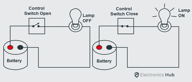
A basic circuit needs a power source, a path for electricity, and a load.
It uses parts like resistors, capacitors, diodes, and transistors. At least one active component is needed for the circuit to work properly.
conducting path
The conducting path is the route that electric current follows in a circuit. Simple circuits use copper wires to carry the current.
In modern electronic circuits, like those found in PCBs, thin copper traces connect the components instead of wires. These traces sit on a non-conductive board.
Voltage Source
The main purpose of a circuit is to allow electric current to flow safely.
For this, a voltage source is required. A voltage source, such as a battery or power supply, provides electrical energy to the circuit.
It creates a difference in voltage between two points, which allows current to flow.
Load
The load is the part of the circuit that consumes electrical energy to perform a function.
Examples of loads include light bulbs, motors, and electronic devices. The load converts electrical energy into other forms of energy, such as light, heat, or motion.
Current
Current is the flow of electric charge through a conductor. It is measured in amperes (A) and represents how many electrons are moving through the circuit per second.
Voltage
Voltage is the electrical potential difference between two points in a circuit. It is measured in volts (V) and represents the force that pushes electric current through the circuit.
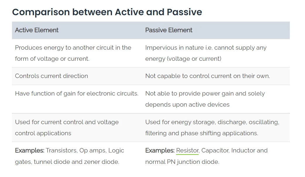
Passive and Active elements
Passive components, such as resistors and capacitors, do not require an external power source to operate. They can only consume energy.
Active components, like transistors and microcontrollers, require an external power source to function and can control the flow of current in a circuit.
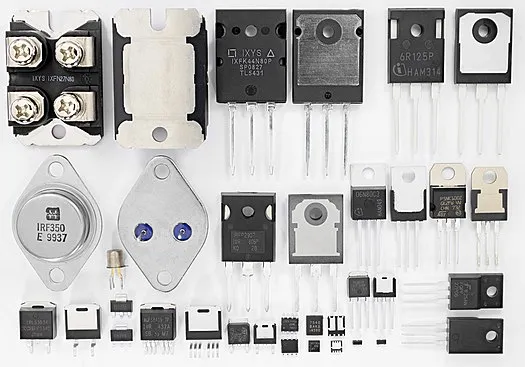
Active Elements
Active components are electronic parts that can control the flow of electricity in a circuit. They require an external power source to operate and can amplify signals or switch currents.
Examples of active components include transistors, diodes, and integrated circuits (ICs). These components are essential for creating complex electronic devices and systems.
Passive Elements
Passive components are electronic parts that do not require an external power source to operate.
They can only consume energy and cannot amplify signals. Examples of passive components include resistors, capacitors, and inductors.
These components are used to control the flow of current, store energy, and filter signals in electronic circuits.

Reference links
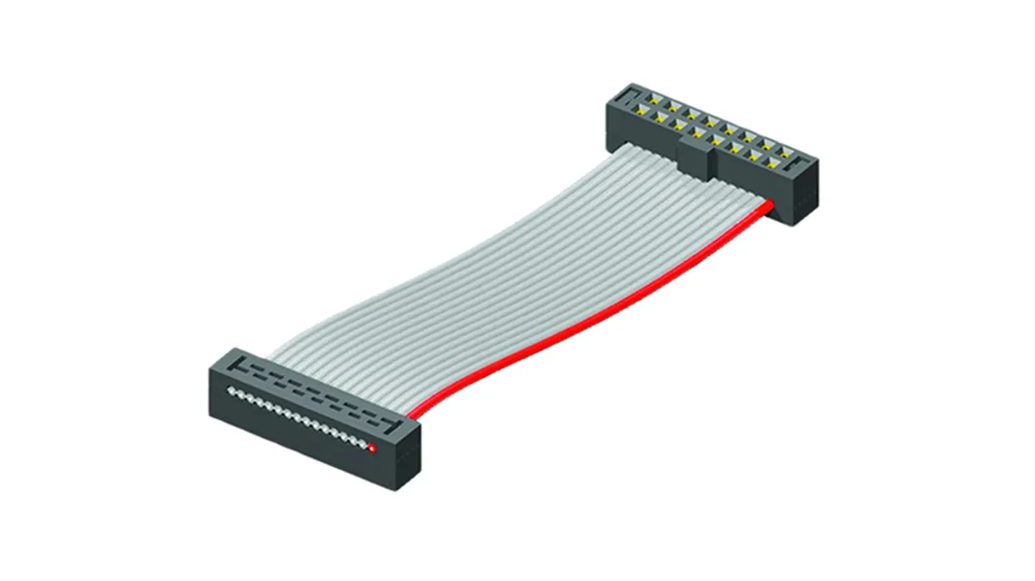
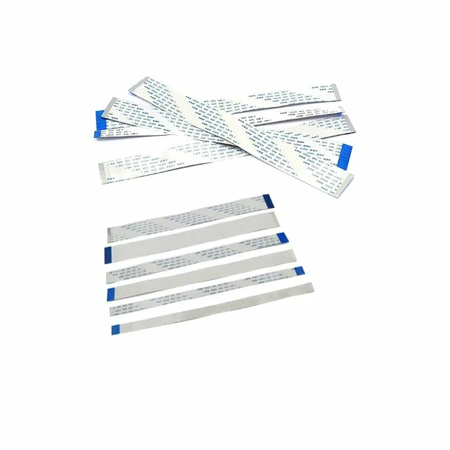
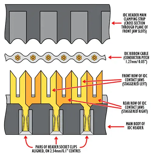
1. Ribbon Cable
A ribbon cable is a flat, wide cable that contains multiple wires running parallel to each other.
It is commonly used to connect different components in electronic devices, such as connecting a microcontroller to a sensor or display.
Ribbon cables are often used in situations where space is limited, as they can be easily folded and routed through tight spaces.
Reference links
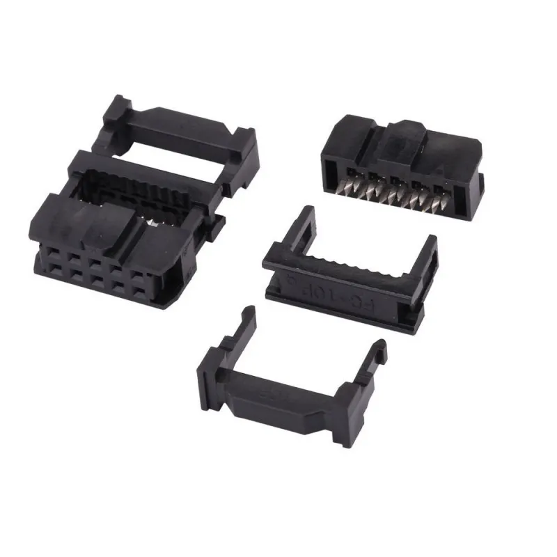
IDC Converter
An IDC (Insulation Displacement Connector) converter is a type of connector used to connect ribbon cables to other components or devices.
It allows for easy and secure connections without the need for soldering. IDC converters typically have a row of pins that match the wires in the ribbon cable, and they can be easily attached or detached as needed.
Reference links
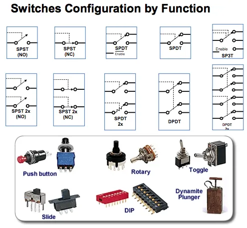
Button
A switch is an electrical device that can be used manually or automatically to break or make an electrical circuit. The ON/ OFF mechanism is the basis for the switch's operation.
Switches are used to regulate or trigger the owl circuit in a variety of electrical or electronic circuits. The many sorts of switches are determined by the circuit connections they make.
Types of Switches
There are four different types of switches, which are:
1) SPST (Single Pole Single throw)
2) SPDT (single pole double throw)
3) DPST (double pole, single throw)
4) DPDT (double pole double throw)
Reference links
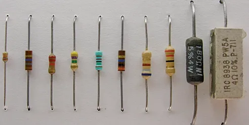
Resistor
A two-terminal passive electrical component that is used to limit or regulate the flow of electric current in electrical circuits. The primary function of a resistor is to reduce current flow and lower voltage in a specific area of the circuit.
Resistors are commonly used to protect components from excessive current, divide voltages, and create specific voltage drops in circuits.
Reference links
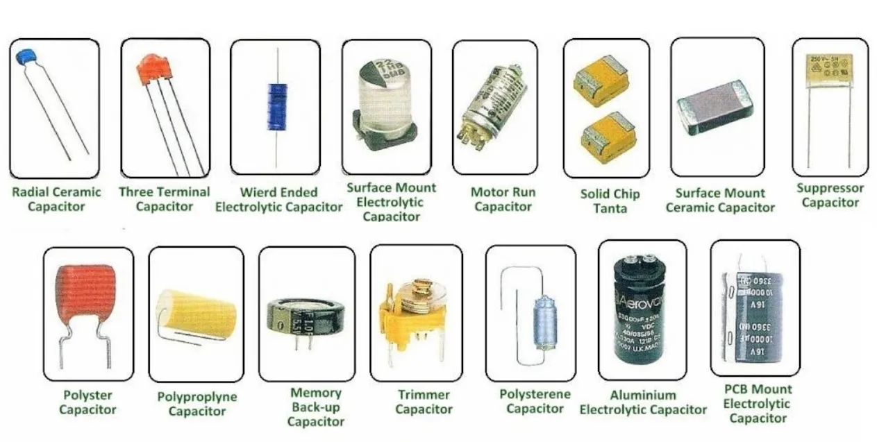
Capacitor
A capacitor is a passive two-terminal electronic component that stores electrical energy in an electric field. It consists of two conductive plates separated by an insulating material called a dielectric.
When a voltage is applied across the plates, an electric field develops, and charge accumulates on the plates. Capacitors are used in various applications, including filtering, energy storage, and signal processing in electronic circuits.
Reference links
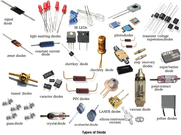
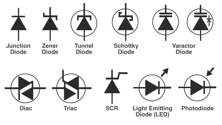
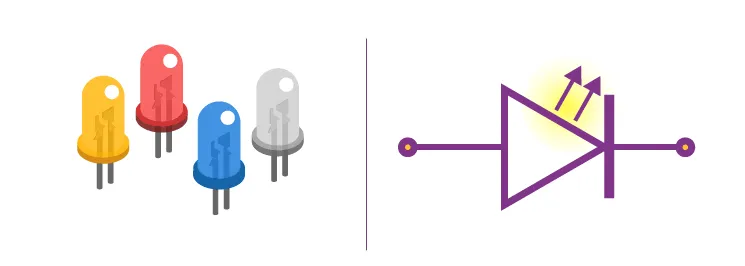
Diode
A diode is a two-terminal electronic component that allows current to flow in one direction while blocking it in the opposite direction. It consists of a semiconductor material, typically silicon, with a positive (anode) and negative (cathode) terminal.
Diodes are commonly used for rectification, signal modulation, and protection in electronic circuits.
Reference links
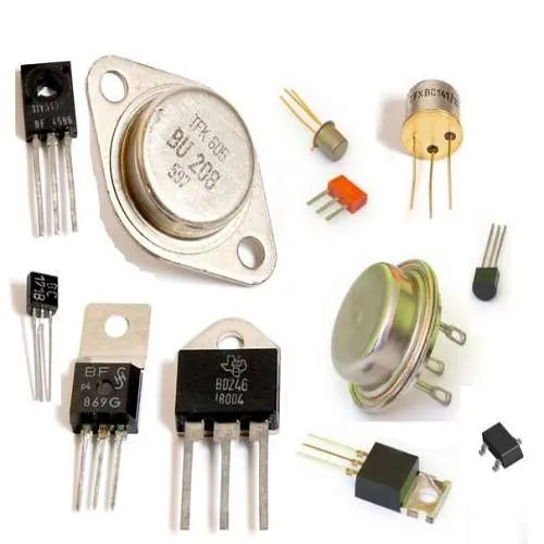
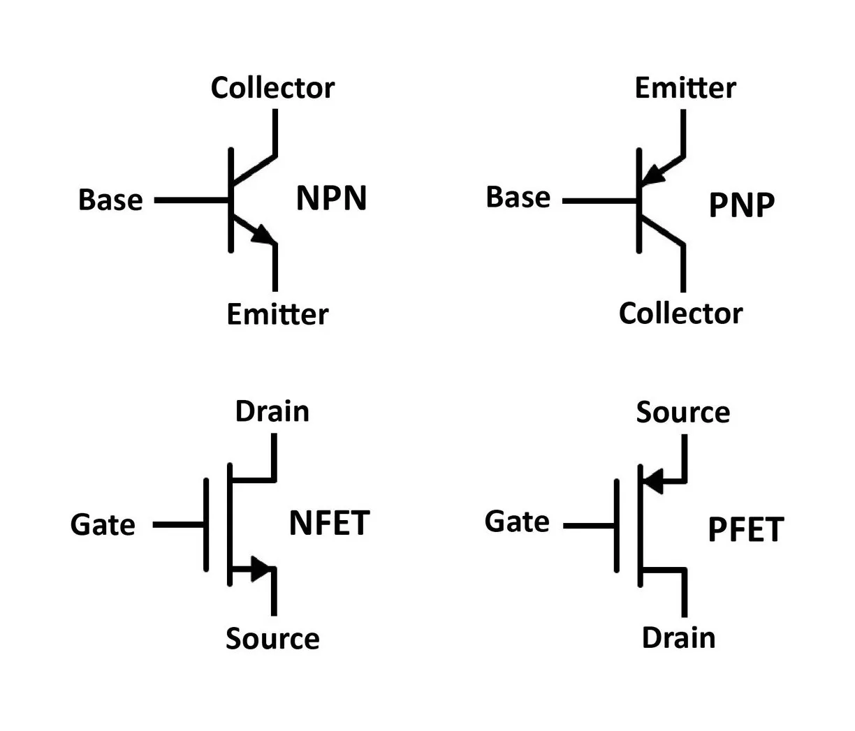
Transistor
A transistor is a three-terminal electronic component that can amplify or switch electronic signals and electrical power. It consists of semiconductor material, typically silicon, with three layers: the emitter, base, and collector.
Reference links
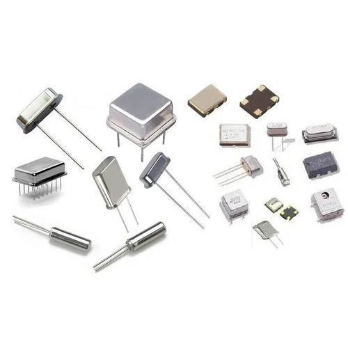
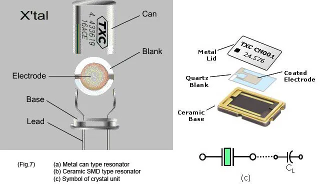
Crystal oscillator
A crystal oscillator is an electronic circuit that uses the mechanical resonance of a vibrating crystal to create an electrical signal with a precise frequency.This frequency is commonly used to maintain track of time,
such as in quartz wristwatches, to provide a stable clock signal for digital integrated circuits, and to stabilize radio transmitter and reception frequencies.
Reference links
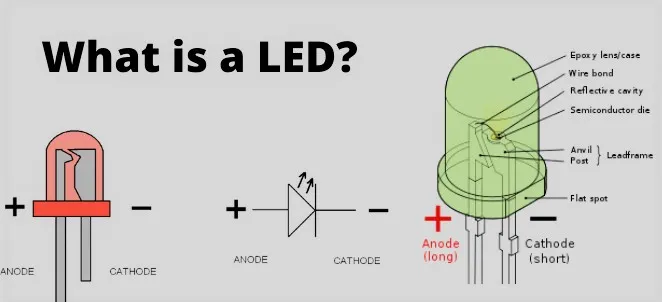
LED
Light is emitted when an electric current passes through a light-emitting diode (LED)an electric current passes through a light-emitting diode (LED),
light is emitted. When current travels through an LED, electrons recombine with holes, resulting in light. LEDs allow current to flow in one direction but prevent it from flowing oppositely the opposite way.
Reference links
MOSFET
A MOSFET (Metal-Oxide-Semiconductor Field-Effect Transistor) is a type of transistor that is widely used in electronic circuits for switching and amplifying signals. It consists of three terminals: the source, drain, and gate.
The MOSFET operates by controlling the flow of current between the source and drain terminals using an electric field generated by the voltage applied to the gate terminal. MOSFETs are commonly used in digital and analog circuits.
Reference links
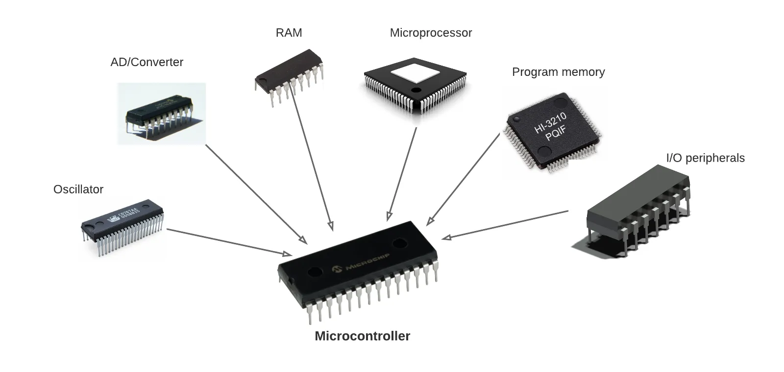
Microcontroller
A microcontroller is a compact, low-cost microcomputer designed to do certain embedded system activities such as displaying microwave information, receiving distant signals, and so on. The CPU, memory (RAM, ROM, EPROM), serial ports, peripherals (timers, counters), and other components make up a generic microcontroller.
Reference links
Group assignment objectives:
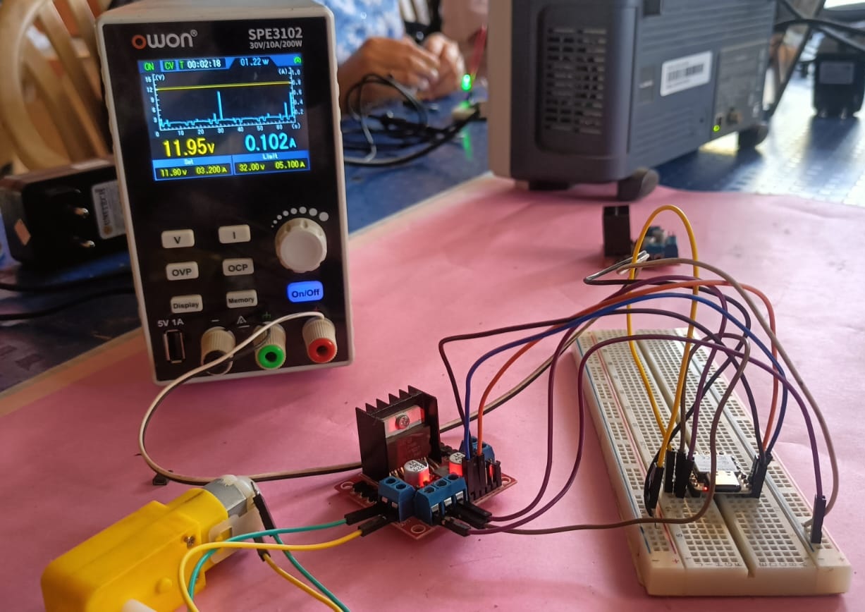
Learn how to use lab test equipment, including a Digital Multimeter, Variable Power Supply, and Oscilloscope.
These tools help you measure and analyze electronic circuits effectively.
Click Here Group Assignment Electronics Design
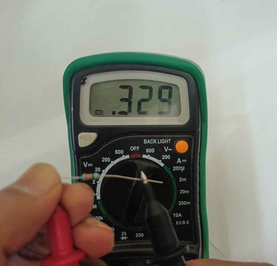
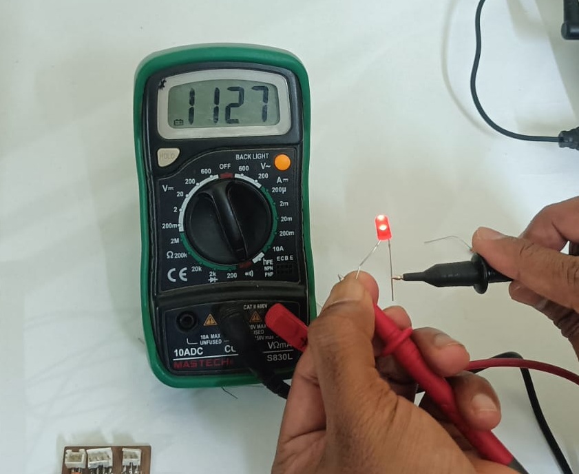
In this group assignment, I learned how to use a multimeter, a variable power supply, and an oscilloscope. During the task, I mainly worked with the multimeter to perform measurements.
To check a resistor, use a multimeter in resistance (Ω) mode and place the probes on both ends. To measure voltage, connect the multimeter in parallel; to measure current, connect it in series, and calculate power using P = V × I.

Individual assignment:-
• Simulate a circuit
• Use an EDA tool to design an embedded microcontroller system
using parts from the inventory, and check its design rules for fabrication.
LTspice simulation software
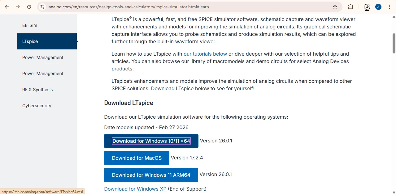
LTspice is a simulation software used to test electronic circuits on a computer. It shows the waveform and behavior of signals in the circuit before building it physically.
Download LTspice
After downloading the file, go to the Downloads folder on your computer.
If the file is compressed (ZIP), right-click on it and select Extract. Then open the extracted folder and double-click the setup file to install the software on your system.
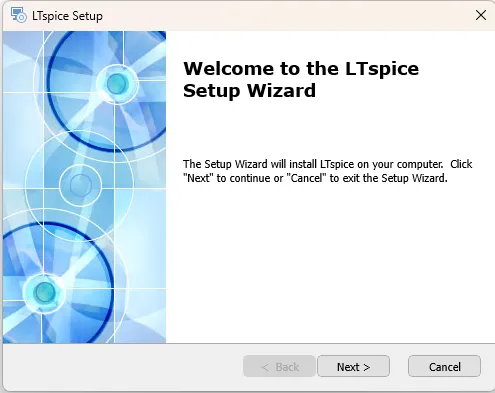
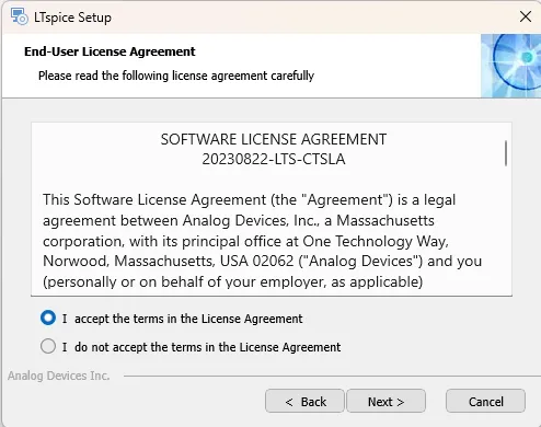
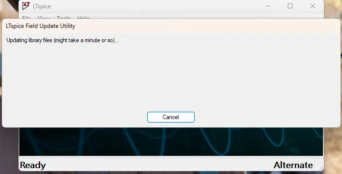
After installation, when you open the software, a window like this will appear. It may show a message asking you to update all libraries.Just press Enter and update all the libraries. It will take only a few seconds to complete.
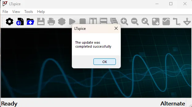
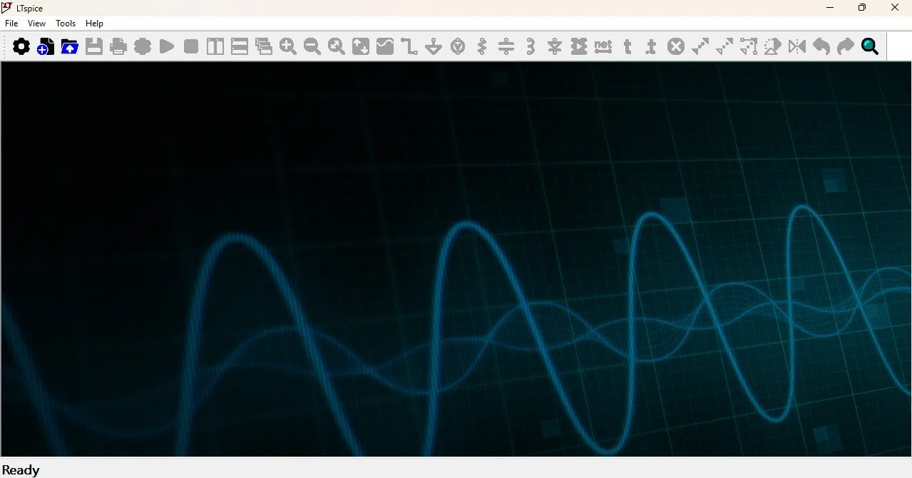
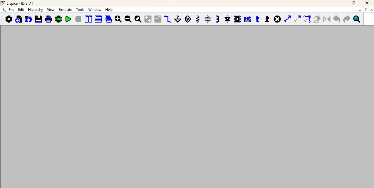
After updating the libraries, you will see the main interface of the software. It may look a bit complex at first, but with practice, you will become familiar with it. You can start by creating a new project and adding components to your circuit design.
1. Transient Simulation
In this software, I learned how to perform Transient Simulation. It shows how voltage and current change over time and helps me see the waveform and behavior of the circuit when signals change.
First, I go to the tools section and selected the voltage source, resistor, and capacitor. Then, I arranged all the components properly and connected them using the wire tool.
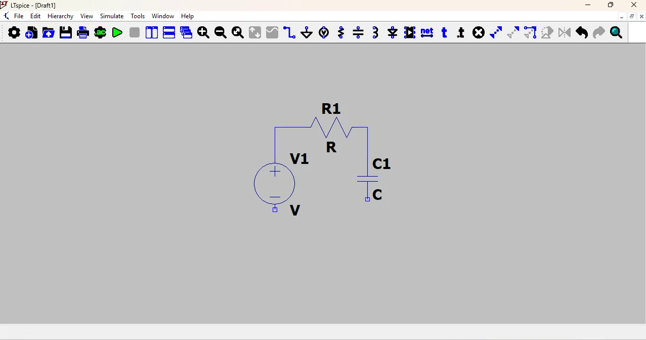
To connect voltage and GND, place the voltage source, then connect its negative terminal to GND (global node 0) using the ground tool.
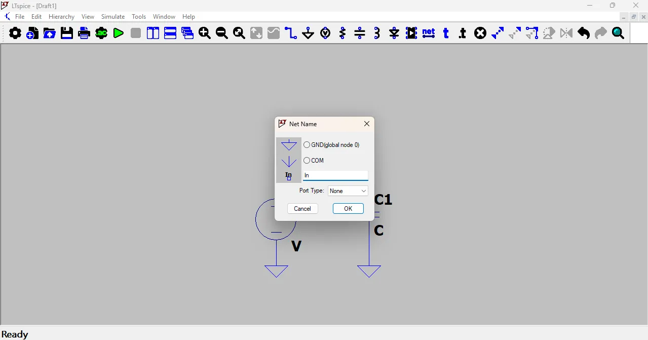
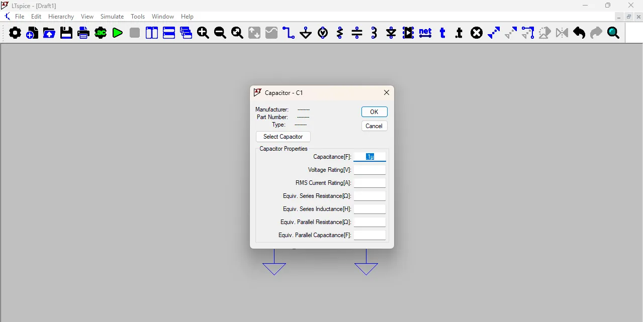
Right-click on the capacitor symbol, and a small window will open where you can enter the capacitor and resistor value Also, go to the Net Label tool and label the circuit nodes as input and output. As shown in the image below.
After that, click on the voltage source and a new window will open. Then click on Advanced, and another popup window will appear, as shown in the image.
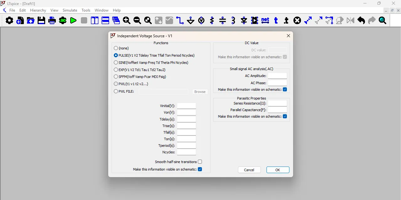
then select the PULSE option and enter the values as shown in the image below. After entering all the values, click OK to close the window.
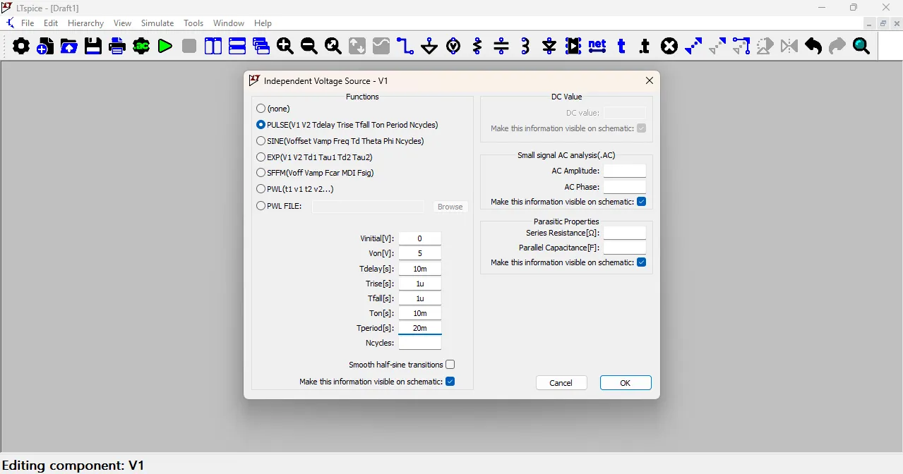
Here, you can see the value you entered, and it is also shown below the component in the circuit. You can move it anywhere to adjust the position clearly.
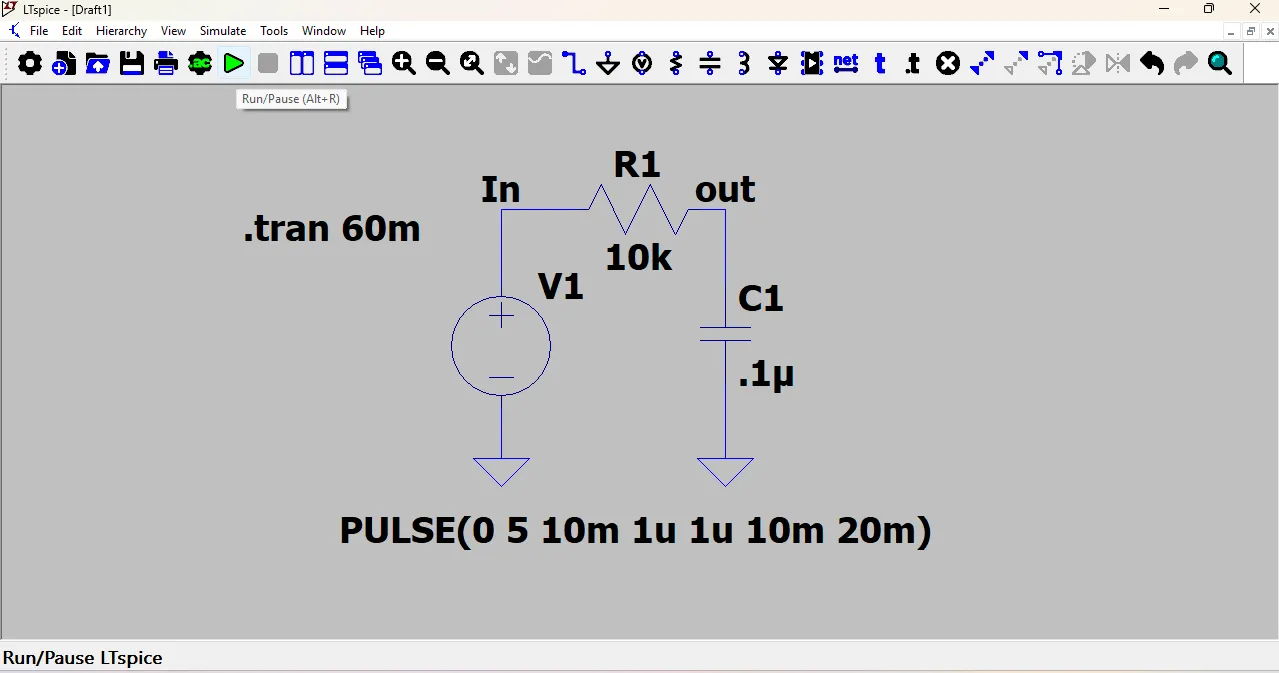
After that, click on Analysis, which is located on the top toolbar near the green Run button.
After a new window opens, select the Stop Time option and enter 60 milliseconds (60ms).
This value will appear in the schematic as .tran 60m which means the transient simulation will run for 60 milliseconds.
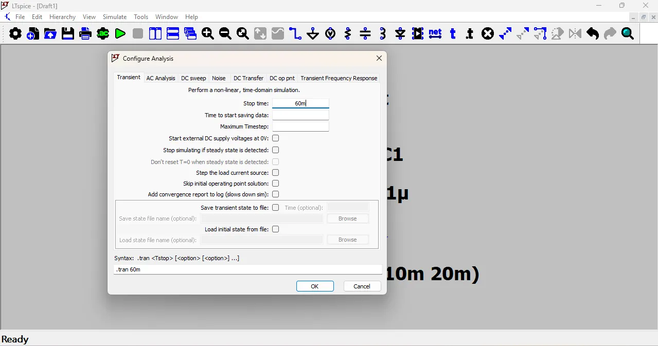
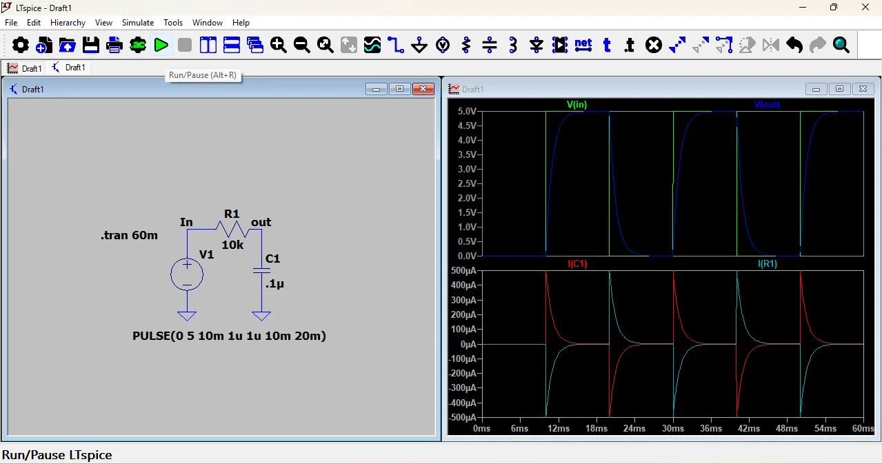
then click OK to close the window. Now, click on the green Run button to start the simulation.
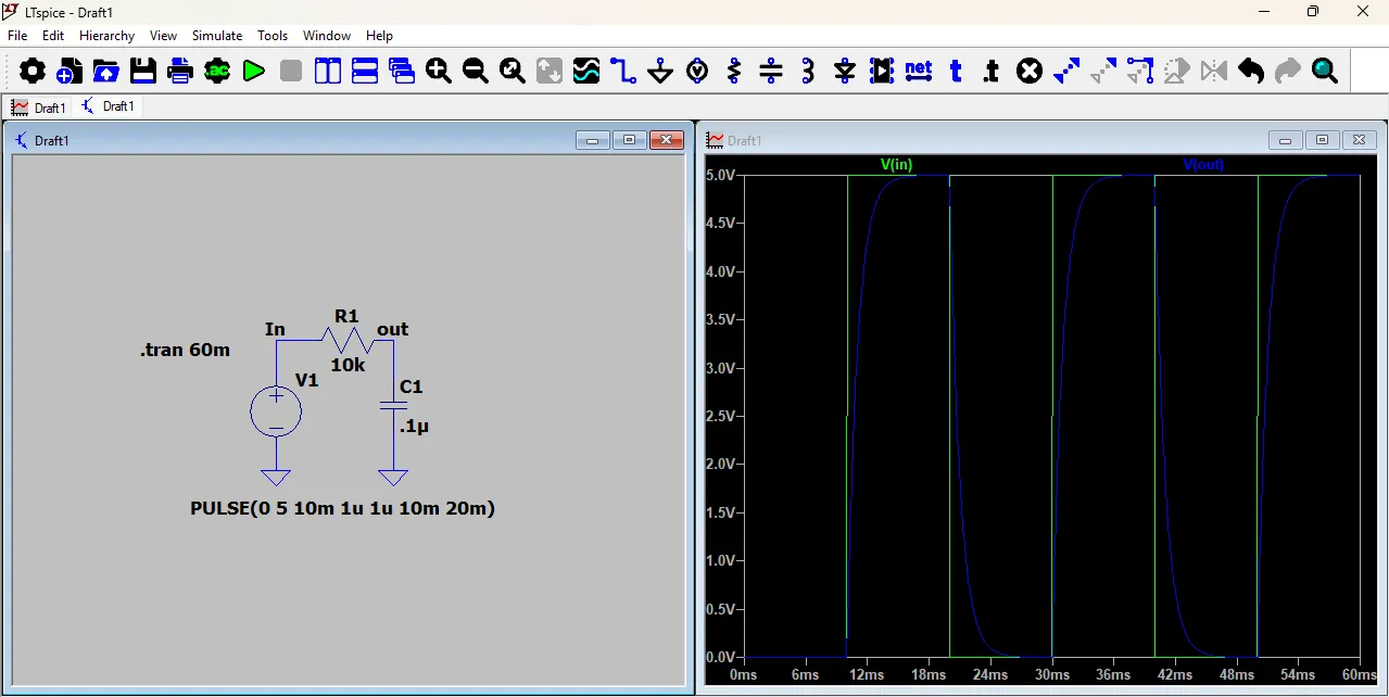
After a few seconds, a new window will open showing the waveform of the circuit. You can analyze the voltage and current changes over time using this graph.
In this graph, the green line shows the input voltage (V_in), which is a square wave signal.
The blue line shows the output voltage (V_out), which charges and discharges slowly because of the RC circuit.
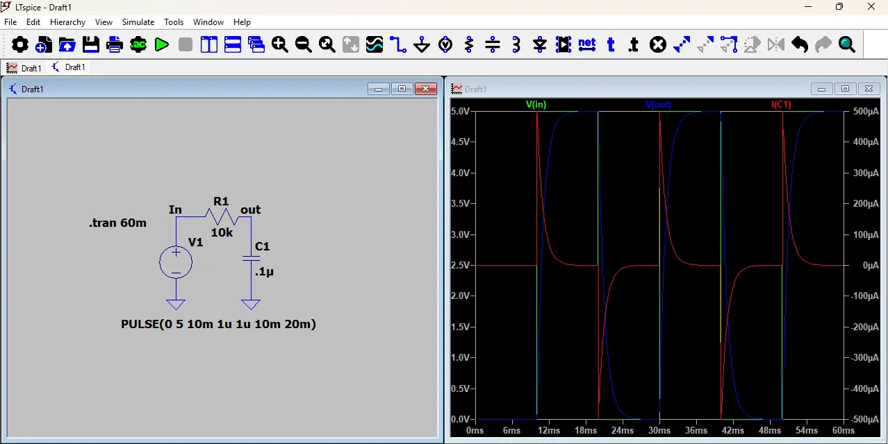
In my RC circuit, I clicked on the capacitor symbol to see its current waveform.
The red line in the graph shows the capacitor current (I(C1)).
When the input changes, the capacitor quickly charges or discharges, so the current increases suddenly.
After that, the current slowly decreases as the capacitor becomes fully charged or discharged.
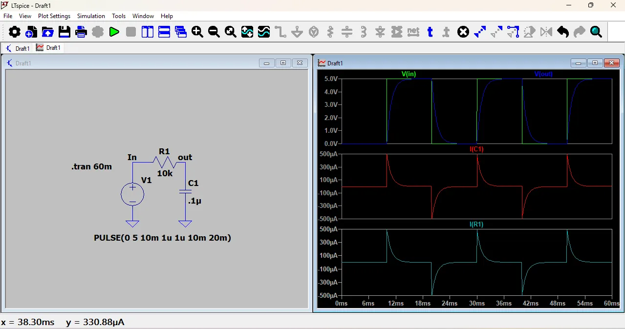
After the voltage and current were shown on the same graph, I wanted to display them separately. So, I right-clicked on the graph area and selected the option to add a new plot pane below. Then, I dragged the current waveform to the lower graph.
To see the resistor current, I clicked on the resistor symbol, and its current waveform appeared in the second graph. Since the resistor current was shown in the negative direction, I checked the current direction by going to View → SPICE Netlist, where the component connections and current direction are defined.
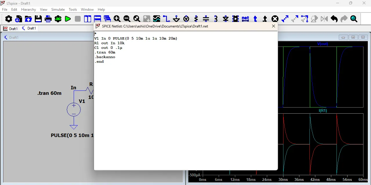
After that, I changed the orientation (direction) of the resistor in the circuit.
Now the resistor current graph is shown in the correct direction.
The waveform looks opposite compared to before because current direction depends on component orientation.
This helped me understand how current direction affects the graph in LTspice.
2. AC Simulation
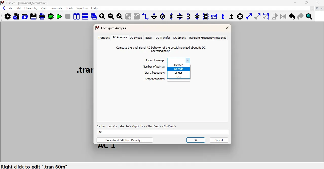
For AC simulation, I used the same RC circuit but made some changes. First, I clicked on Analysis from the top toolbar near the green Run button. Then a new window opened, and I selected the AC Analysis tab.
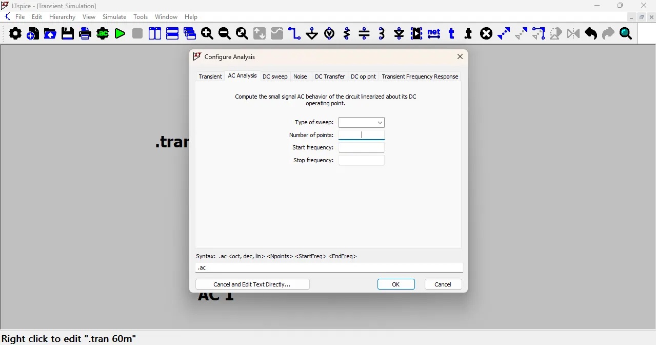
In the AC Analysis window, I selected the Type of Sweep as Decade and entered the Start Frequency as 1Hz and the Stop Frequency as 1MHz.
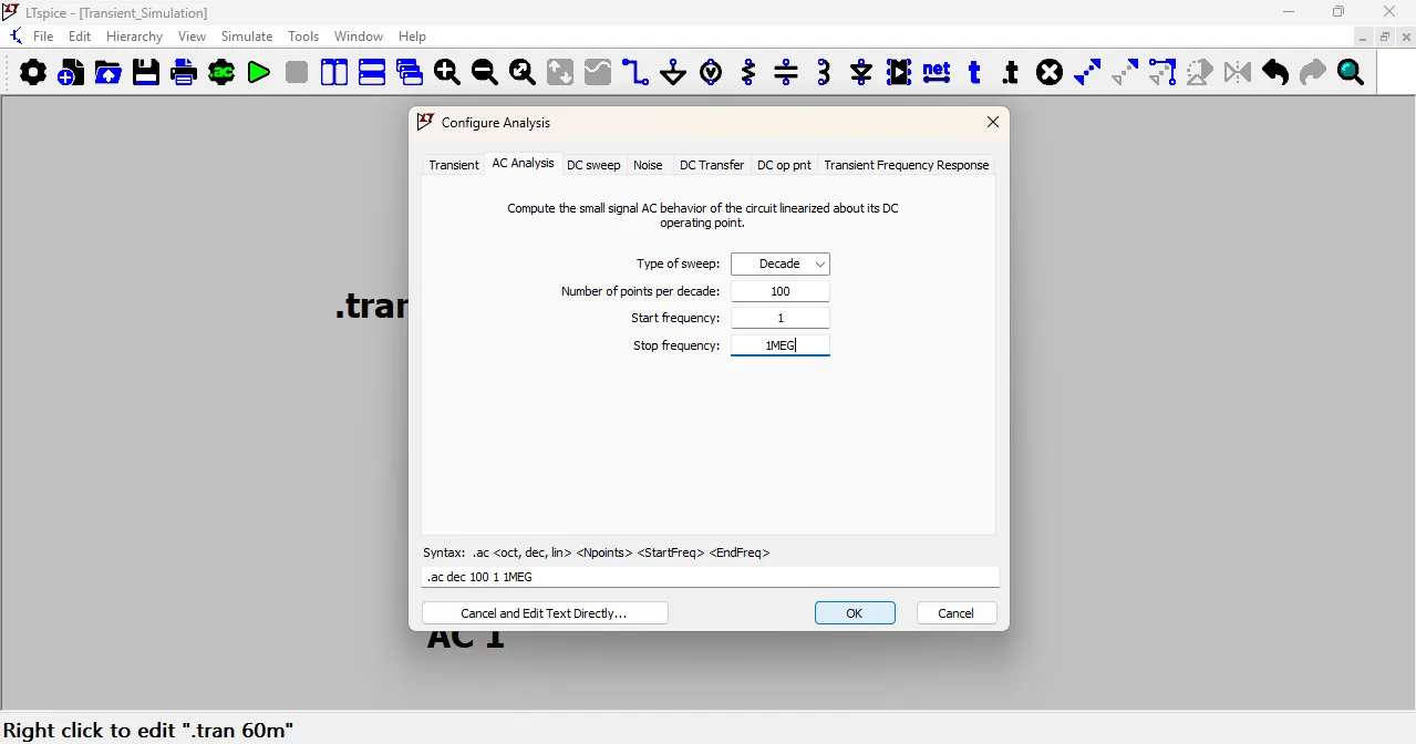
After entering all the values, I clicked OK to close the window. Then, I clicked on the green Run button to start the AC simulation.
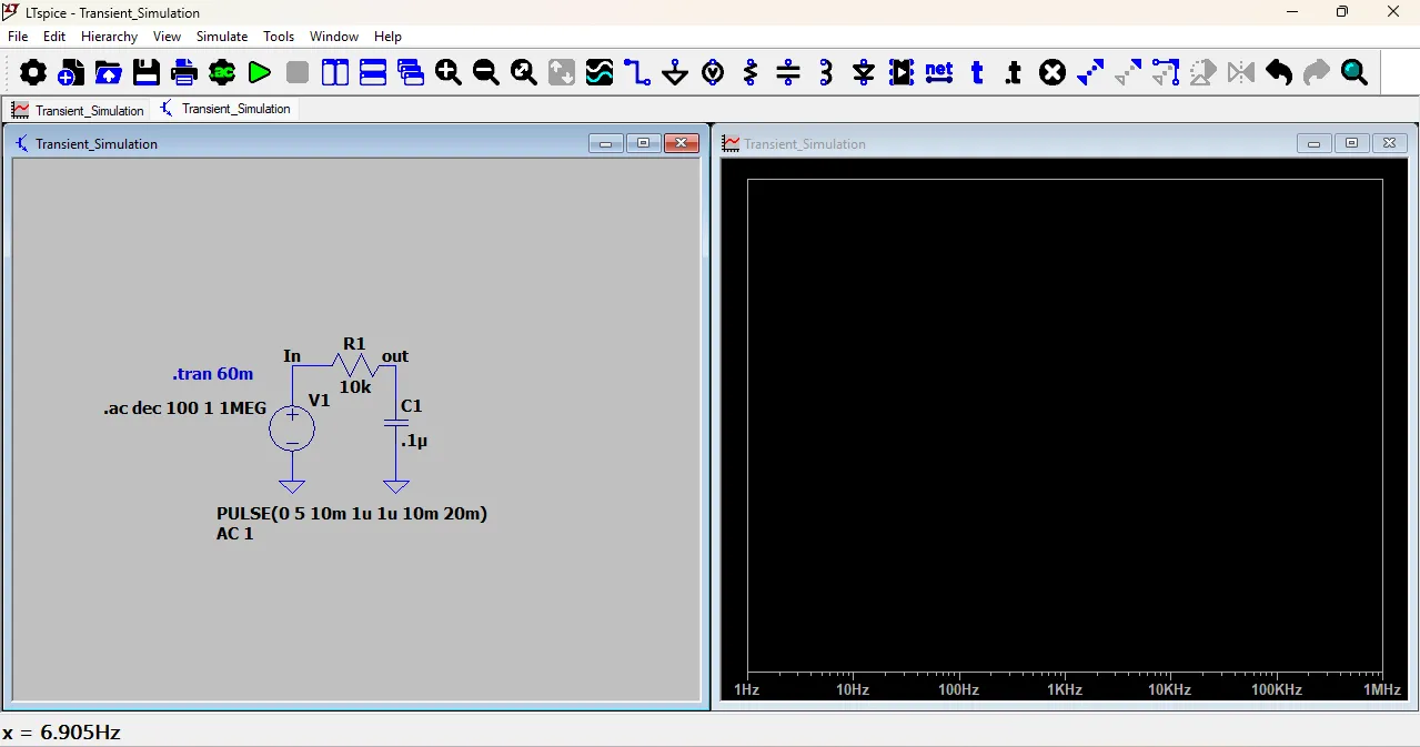
After a few seconds, a new window opened showing the Bode plot of the circuit. The Bode plot consists of two graphs: the magnitude plot and the phase plot.
The magnitude plot shows how the amplitude of the output signal changes with frequency, while the phase plot shows how the phase of the output signal changes with frequency.
In my RC circuit, the magnitude plot shows that at low frequencies, the output voltage is almost the same as the input voltage,
but as the frequency increases, the output voltage decreases due to the capacitive reactance. The phase plot shows that at low frequencies, the output voltage is in phase with the input voltage,
but as the frequency increases, the output voltage lags behind the input voltage due to the capacitive effect.
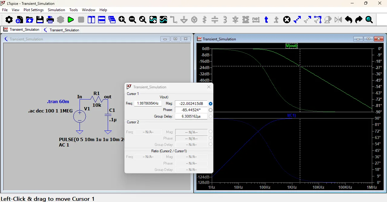
This is the AC analysis (frequency response) of the RC circuit.
The top graph shows the output voltage (Vout) in dB and its phase. As frequency increases, the output decreases. This means it is a low-pass filter — it allows low frequencies to pass and reduces high frequencies.
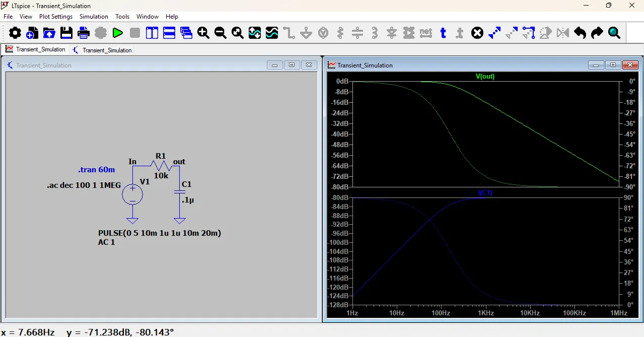
The cutoff frequency (fc) can be calculated using the formula:
𝑓𝑐=1/2𝜋𝑅𝐶fc
Here,R = 10kΩ, C = 0.1µF
𝑓𝑐=1/2𝜋(10000)(0.1×10power-6)
fc =2π(10000)(0.1×10power-6)
𝑓𝑐≈159 Hz
For the cutoff frequency calculation, I used ChatGPT to help me understand the formula and compute the value correctly. This helped me learn how to apply the formula
fc=1/(2πRC) to my RC circuit.
From this, I learn:
The circuit works as a low-pass filter.
Around 159 Hz, the output drops to -3 dB (cutoff point).
Above this frequency, the signal decreases rapidly.
Wokwi
Wokwi is a simulation software used to test microcontroller projects online.
You can add your microcontroller board, input and output devices, and upload your code.
It allows you to run the complete system virtually before building the real circuit.
If the code works properly in simulation, the circuit is more likely to work correctly in real life.
It gives a better understanding of how the system behaves.
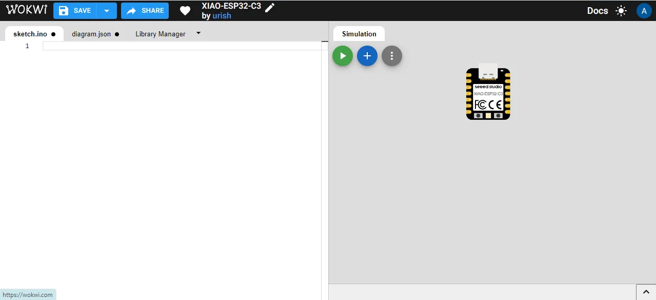
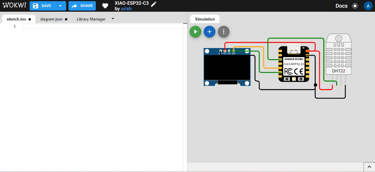
Start New Wokwi Project

After that, select your board. Here, I selected the ESP32-C3 board because I am using it in my project.
In my project, I am using a DHT sensor as an input device and a display module as an output device, so I want to simulate the system with ESP32-C3, DHT, and display.
In the first step, I selected the ESP32-C3 board
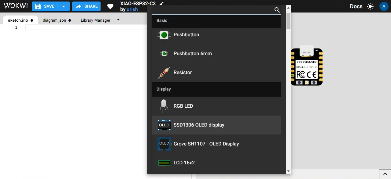
Click on the plus (+) sign to add components like the display module.
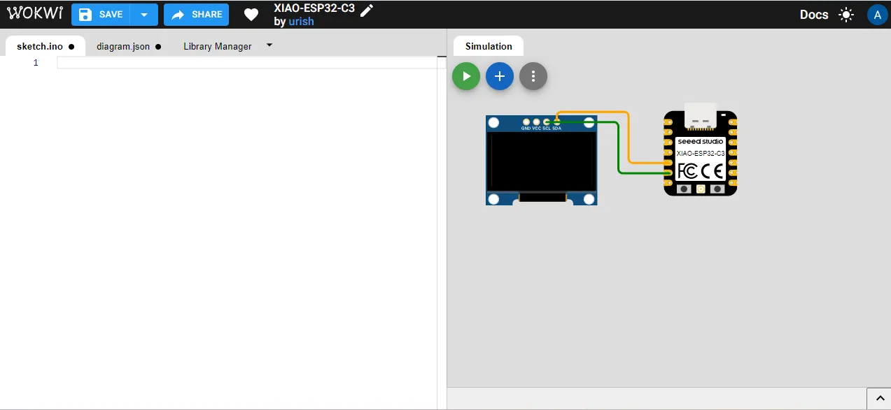
Before connecting the wires, I checked the pin diagram to find the correct pins for the display.

Then connect the display to the ESP32-C3 microcontroller board using jumper wires according to the required pins.
After that, I added the DHT22 sensor to the project and connected it to the ESP32-C3 board according to the correct pin configuration.
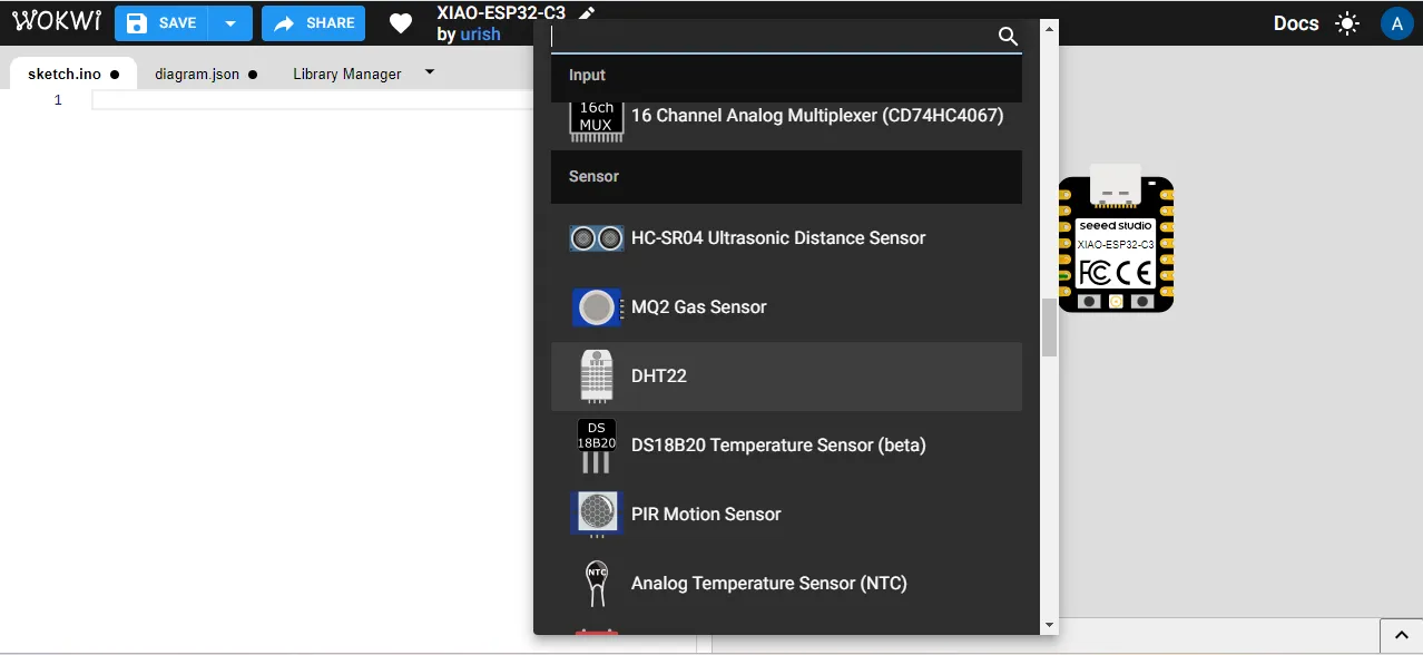
Then I connected the DHT22 sensor and the OLED display to the ESP32-C3 module using jumper wires. I made sure all pins were connected correctly according to the pin diagram.
After that, I created the code for the DHT sensor with the help of ChatGPT.
The code reads temperature and humidity values and displays the data on the OLED screen.
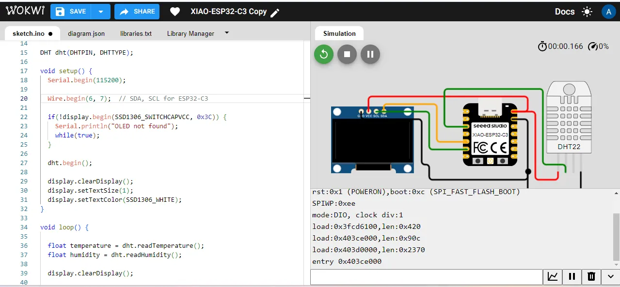
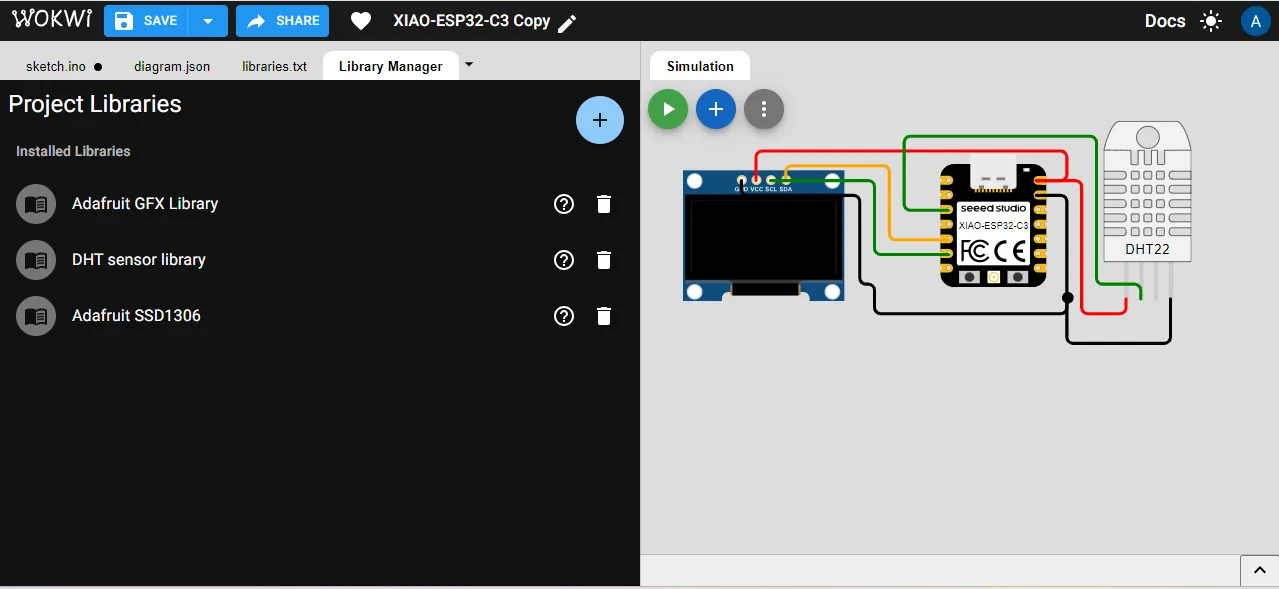
After writing the code, the required libraries are automatically installed in Wokwi.
Wokwi supports many built-in libraries, so there is no need to install them manually.
This makes the simulation process simple and easy to use.
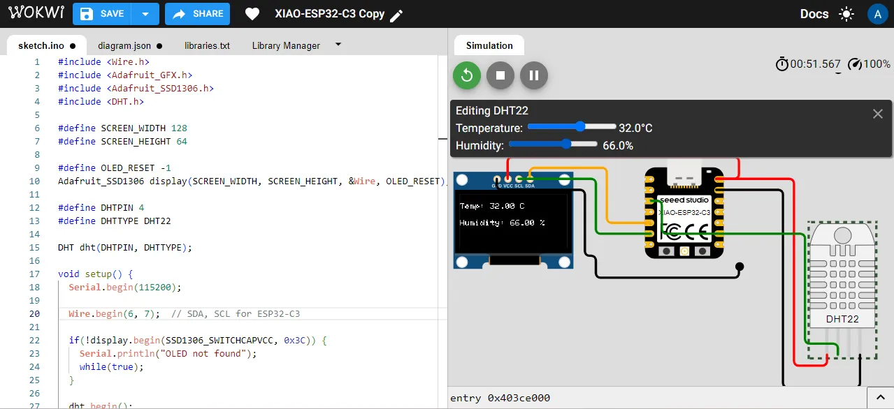
After that, I uploaded the code to the Wokwi simulator and ran the simulation. The output was displayed on the OLED screen, showing the temperature and humidity values read from the DHT22 sensor.
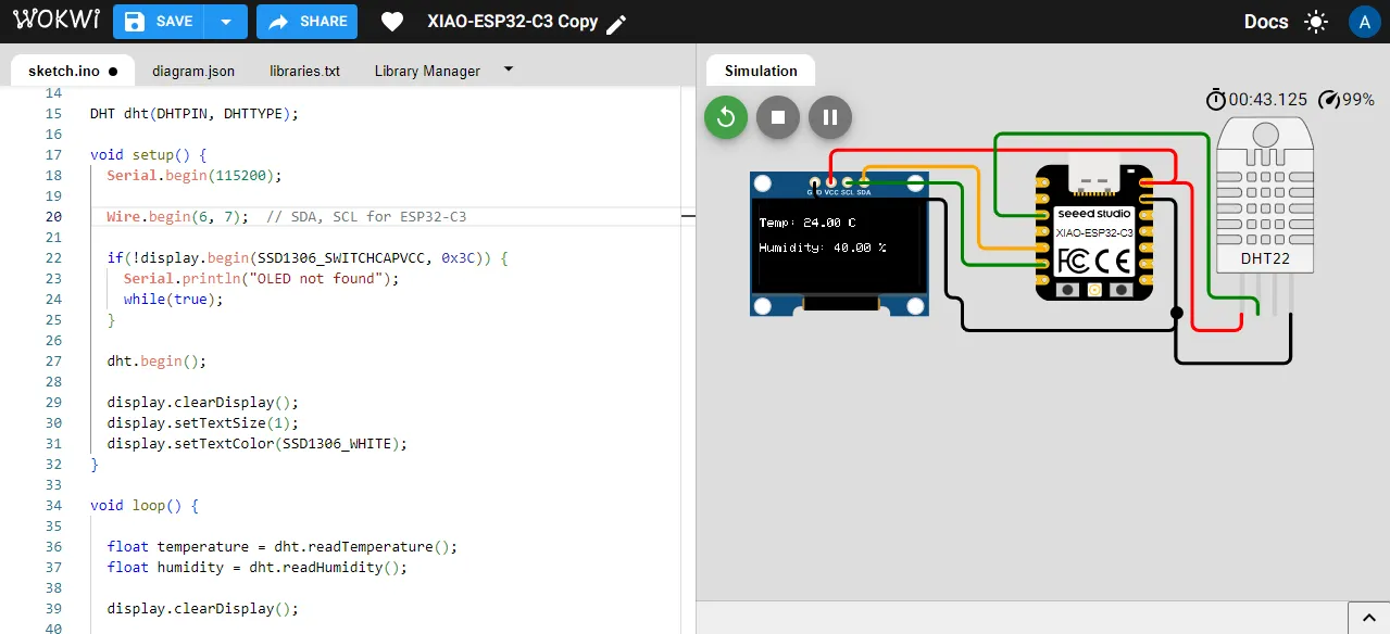
If you click on the DHT22 sensor in Wokwi, it shows slider bars for temperature and humidity.
You can move the sliders to change the temperature and humidity values.
The updated values will automatically appear on the OLED display during simulation.
kicad
KiCad is an open-source software used for designing printed circuit boards (PCBs).
It allows you to create schematics, design PCB layouts, and generate files needed for manufacturing.
KiCad provides tools for checking design rules and ensuring that your PCB design is correct before fabrication.
why I choose kicad?
I choose KiCad for PCB design because it is a powerful and widely used EDA tool that offers a comprehensive set of features for schematic capture and PCB layout.
KiCad is open-source and free to use, making it accessible for students and professionals alike. It has a large community and extensive libraries of components,
which makes it easier to find and use the parts needed for my design. Additionally,
KiCad provides robust design rule checks (DRC) and electrical rule checks (ERC) to ensure that my PCB design meets the necessary standards for fabrication.
DRC and ERC
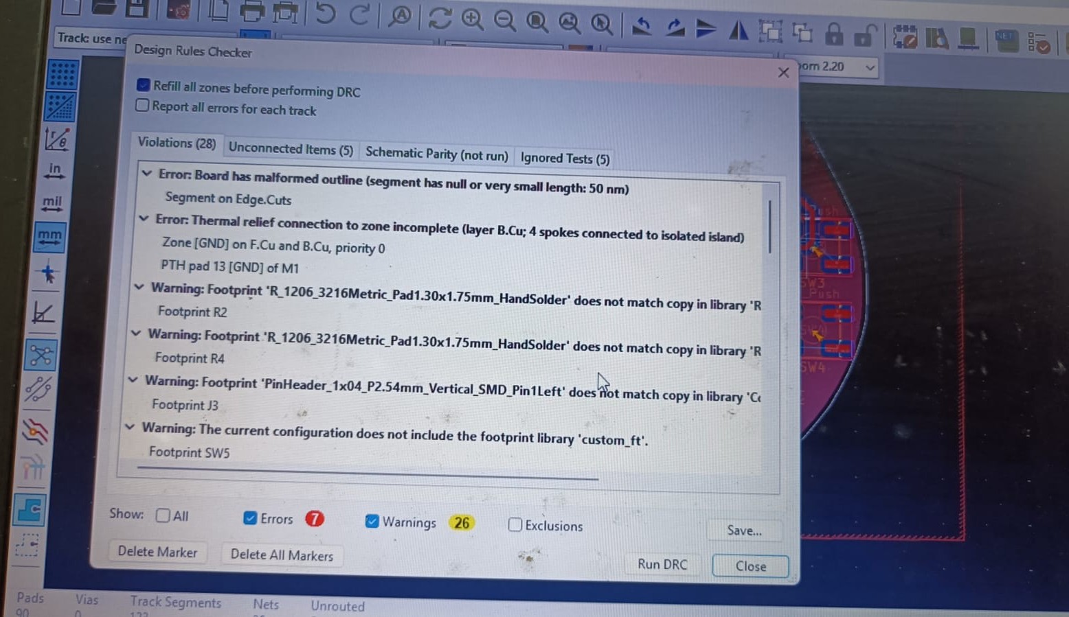
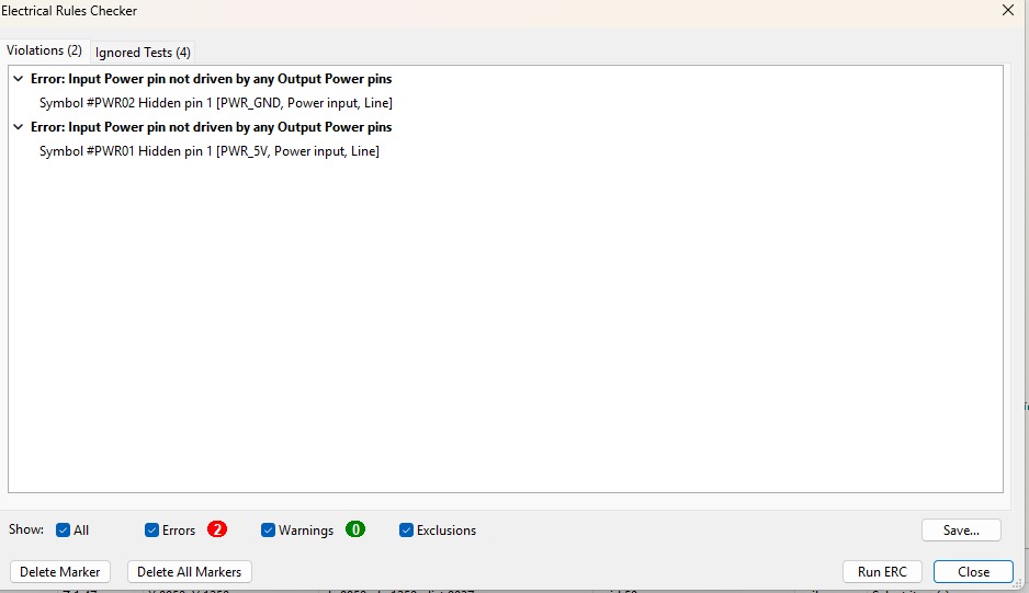
DRC (Design Rule Check) and ERC (Electrical Rule Check) are essential tools in PCB design that help ensure the integrity and functionality of the circuit.
DRC checks the physical layout of the PCB against predefined design rules, such as minimum trace width, spacing between components, and clearance around pads.
It helps identify potential issues that could arise during manufacturing or operation, such as short circuits or insufficient clearance.
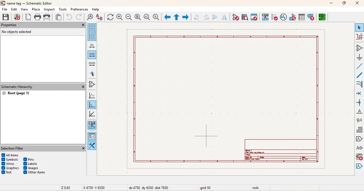
This image shows the interface of KiCad, where you can see the schematic design and PCB layout tools. The DRC and ERC checks can be accessed from the toolbar to validate the design before proceeding to fabrication.
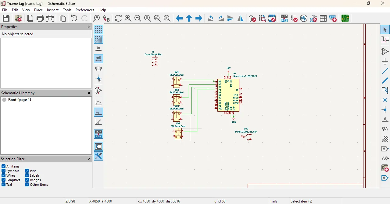
After that, i add footprint and symbol of the components in the library and then i created the schematic design of my project using those components.
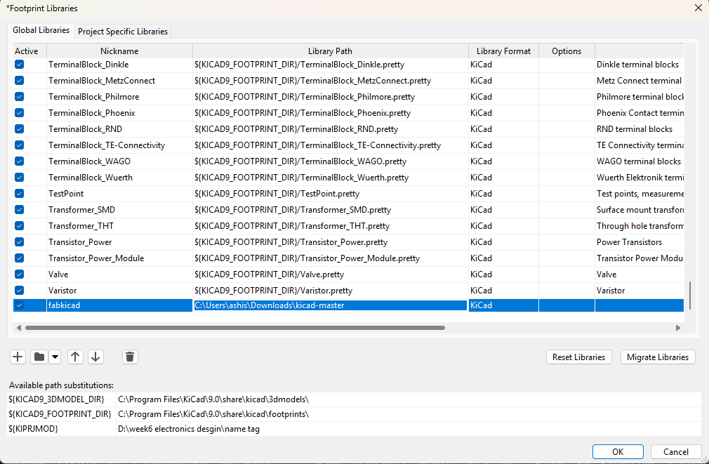
here, can see the install all libraries in kicad.
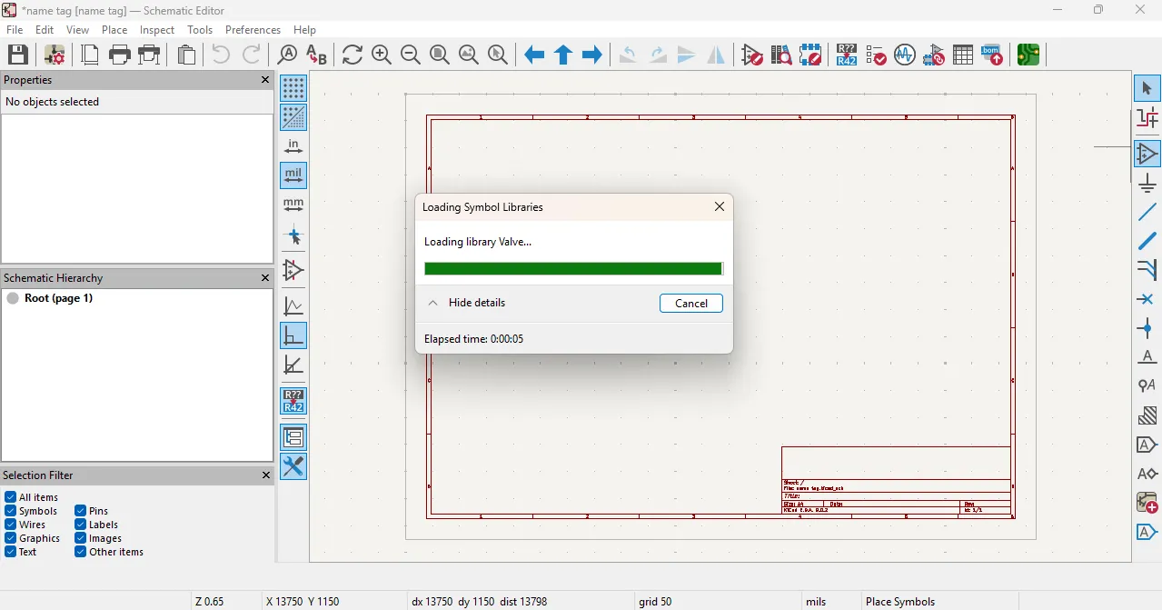
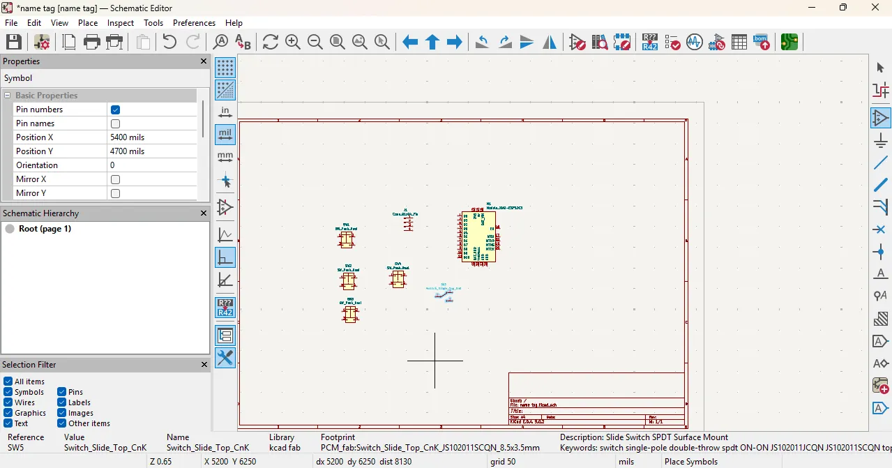
After installing the KiCad library, I chose the components to make the schematic.
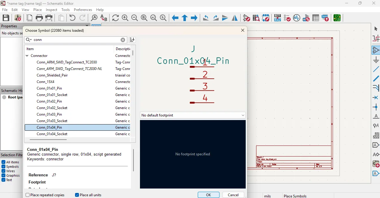
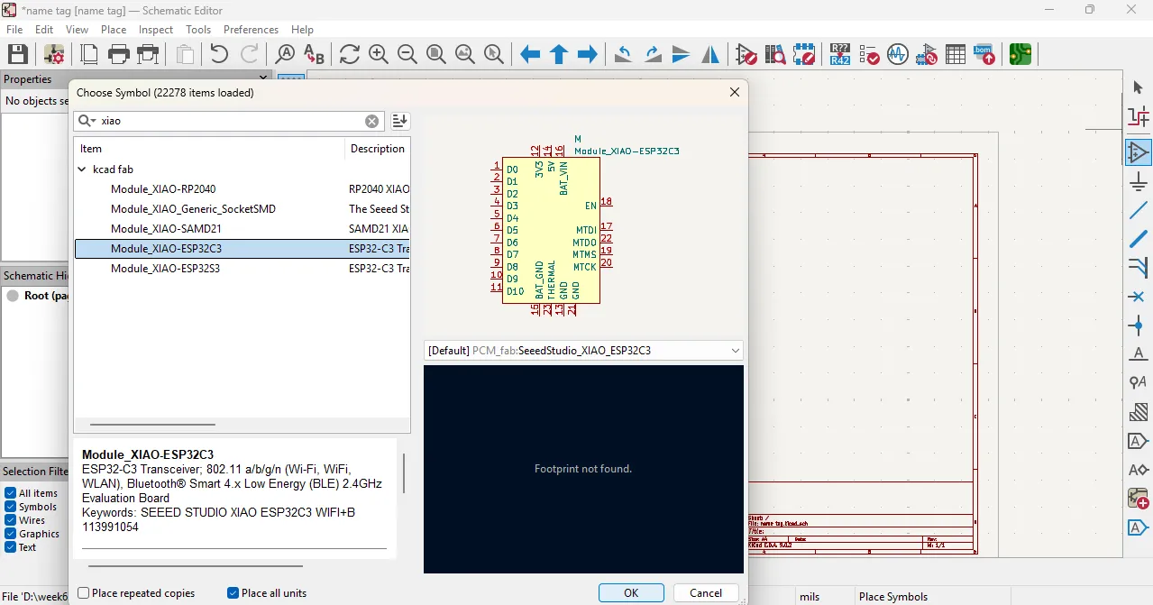
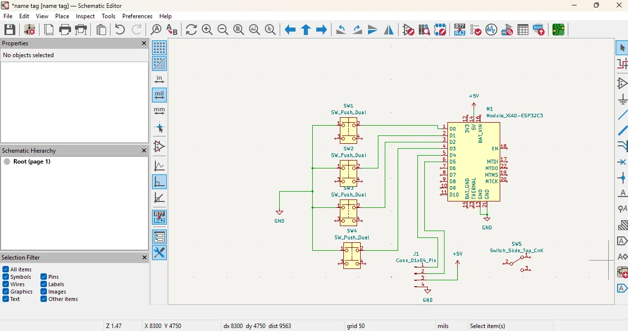
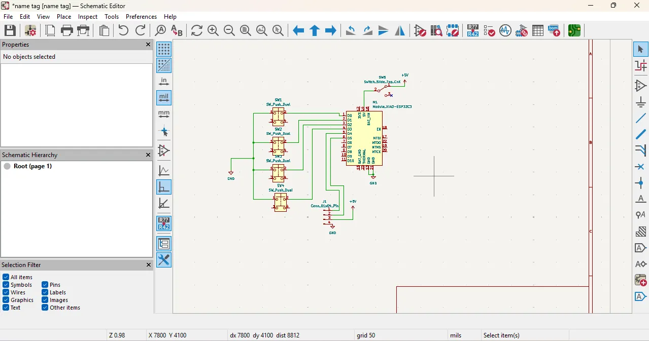
After choose the all components, i arrenged all the components properly and connecting them using the wire tool.
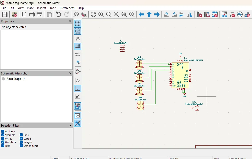
After that, i checked the schematic design after that i went to the pcb layout and imported the schematic design to the pcb layout and then i arrenged all the components in the pcb layout and connecting them using the track tool.
After that, dounload cat head image from the google and thrn i use it in the pcb layout as a logo and resize it according to the pcd arrangement all components and rounting the tracks properly and then i checked the design rules.
in this design, i use the cat head image as a logo for my PCB design. I placed the logo in the center of the PCB layout and resized it to fit within the design.
this image download from this link image reference

After routing the tracks properly, I checked the design rules using DRC and ERC checks to ensure that there are no errors in the schematic and PCB layout finally, looks like this.
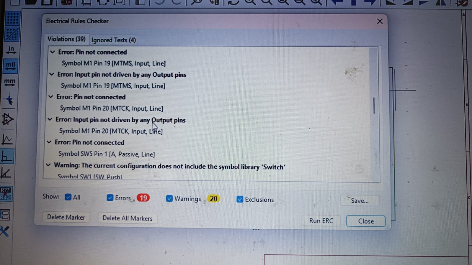
The final PCB layout was generated after verifying the PCB design using the DRC (Design Rule Check) and fixing all the design errors, as shown below.
After checking the design, the 3D view of my PCB looks like this.


Problems
1) During the LTspice simulation, I faced some issues with the waveform display. Initially, the voltage and current waveforms were shown on the same graph, which made it difficult to analyze them separately. To solve this, I right-clicked on the graph area and added a new plot pane below. Then, I dragged the current waveform to the lower graph, allowing me to view the voltage and current waveforms separately for better analysis.
2) In the Wokwi simulation, I encountered a problem with the code for the DHT sensor. The code was not working correctly, and I was unsure how to fix it. To resolve this issue, I used ChatGPT to help me understand the code and identify the errors. With the assistance of ChatGPT, I was able to correct the code and successfully run the simulation, allowing me to see the temperature and humidity values displayed on the OLED screen.
3) While designing the PCB layout in KiCad, I faced challenges with routing the tracks properly. The initial layout had some overlapping tracks and insufficient clearance between components. To address this, I carefully rearranged the components and used the track tool to route the connections while ensuring that there were no overlaps and that the design rules were met. After making these adjustments, I ran the DRC check to confirm that the layout was error-free before finalizing the design.
Refrences:
1) LTspice Simulator
2) Wokwi Simulator
3) KiCad Software
4) Cat Head Image
5) ChatGPT use for the grammar check
Download all files from here