Assignment 2:- Computer-Aided Design
learing outcome
In the second session, the topic was Computer-Aided Design (CAD). In this session, I learned about 2D and 3D design and explored different software used for both 2D and 3D designing. As part of this assignment, I performed tasks related to raster and vector graphics, 2D and 3D modeling, animation, simulation, and rendering. I also used some video editing software to understand how visual content can be created and presented effectively.
2D software
Raster and Vector
Raster images are made of pixels. When we zoom in on a raster image, the quality of the image reduces and becomes blurry.
Raster images are mainly used in photo editing software such as Adobe Photoshop and GIMP.
Vector images are made using lines and shapes. When we zoom in or zoom out on a vector image, the quality remains the same and does not lose clarity.
Vector software is mainly used for logo design and drawings. For this purpose, software such as CorelDRAW and Inkscape is commonly used.
Why I'm choose the this software
For the 2d desigen
I chose Inkscape and GIMP software for 2D designing because both of these open source software are widely used in the industry for 2d designing and photo editing.
Inkscape is a powerfull software that allows me to create detailed and accurte 2D designs with ease. it has a user friendly interface and a wide range of tools and features that make the desgin process efficient and effective.
inkscape lagre community support and a lot of online resources, and tutorials are available, which mkaes it easy for mr to learn and use this software.
GIMP is also a greate software that provides a clean and in tuitive interface wchich makes its easy to learn and use. GIMP is also a cost effective software for photo editing, as it's free and open source. its also a powerfull software that provides a widee range of tools and fatures for photo editing,
wchich makes its a greate choice for mr to learn and use for my photo editing needs. bothse are in indusrty standaed software that are widely used in the filed of 2D designing and photo editing.
inkscape
I started working with Inkscape, which is an open-source software. I downloaded it from the official Inkscape website using this link:
Inkscape Download
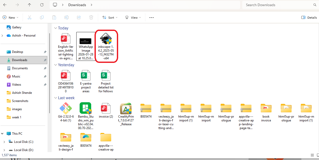
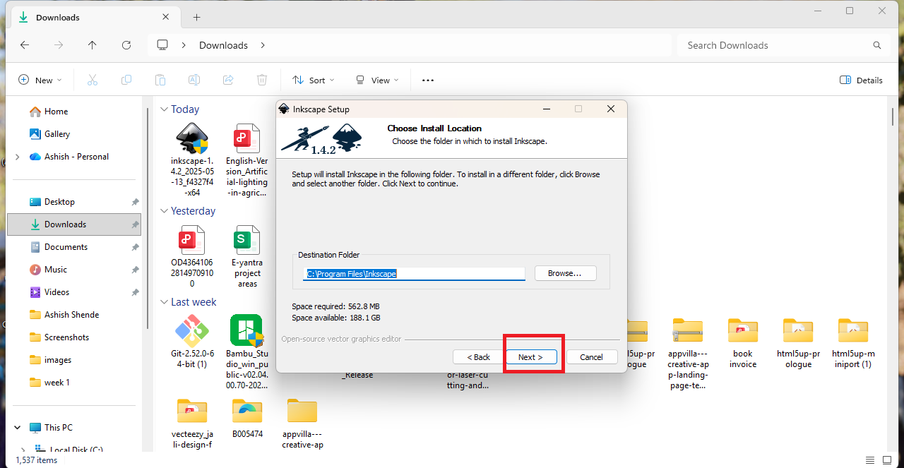
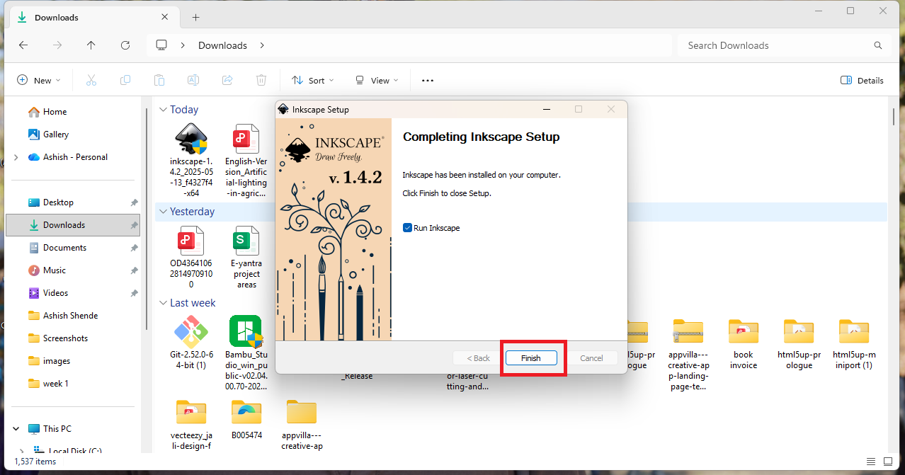
I installed Inkscape on my system using the downloaded file and completed the installation by clicking Next.
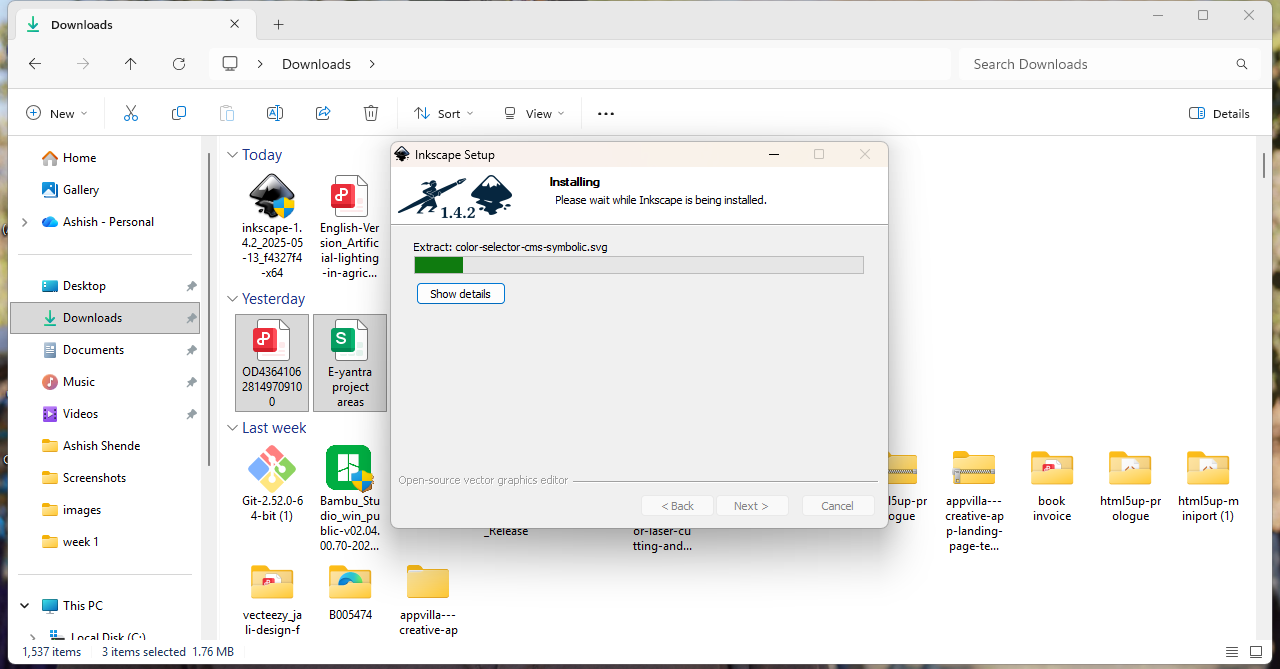
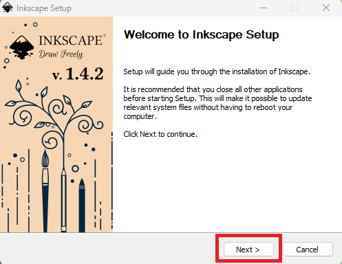
After the installation was completed, a new window opened click on next and finish.
I wanted to learn how to design a logo using Inkscape, so I watched a tutorial video on YouTube. This video helped me understand the basic tools and steps for logo design:
Inkscape Logo Design Tutorial
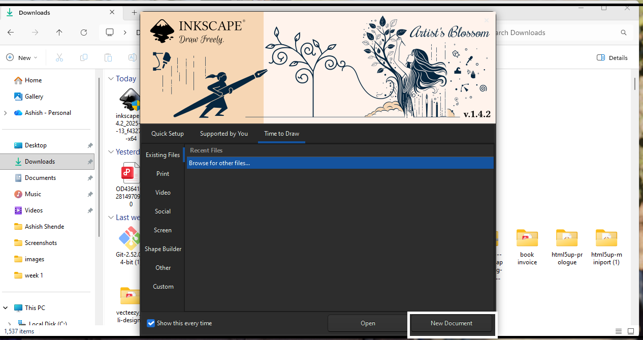
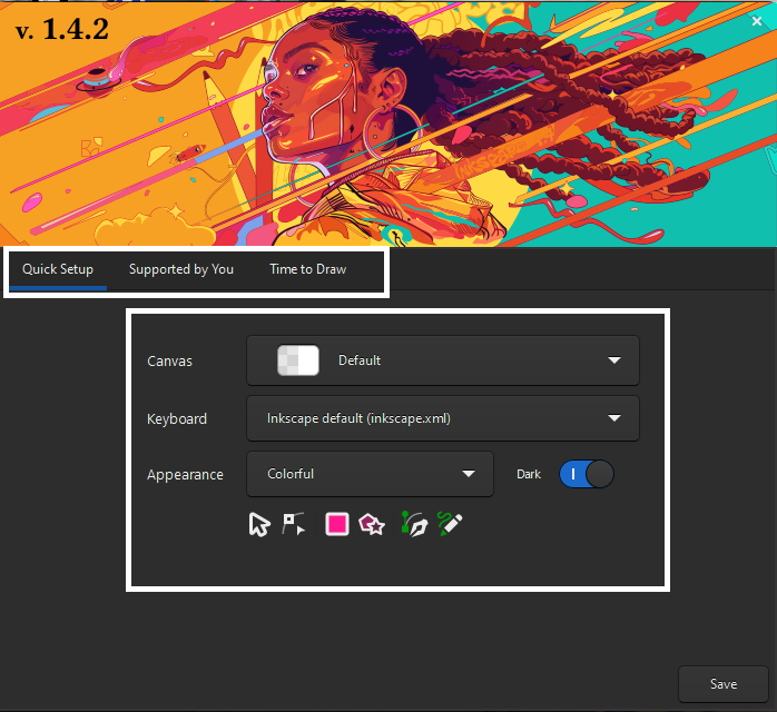
When I clicked Start, a new window opened showing different options for the screen layout. I selected the default settings.
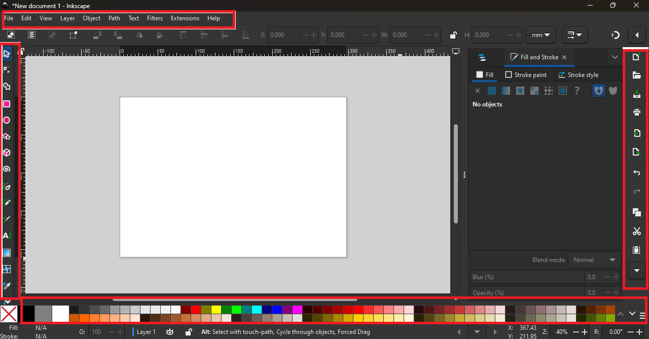
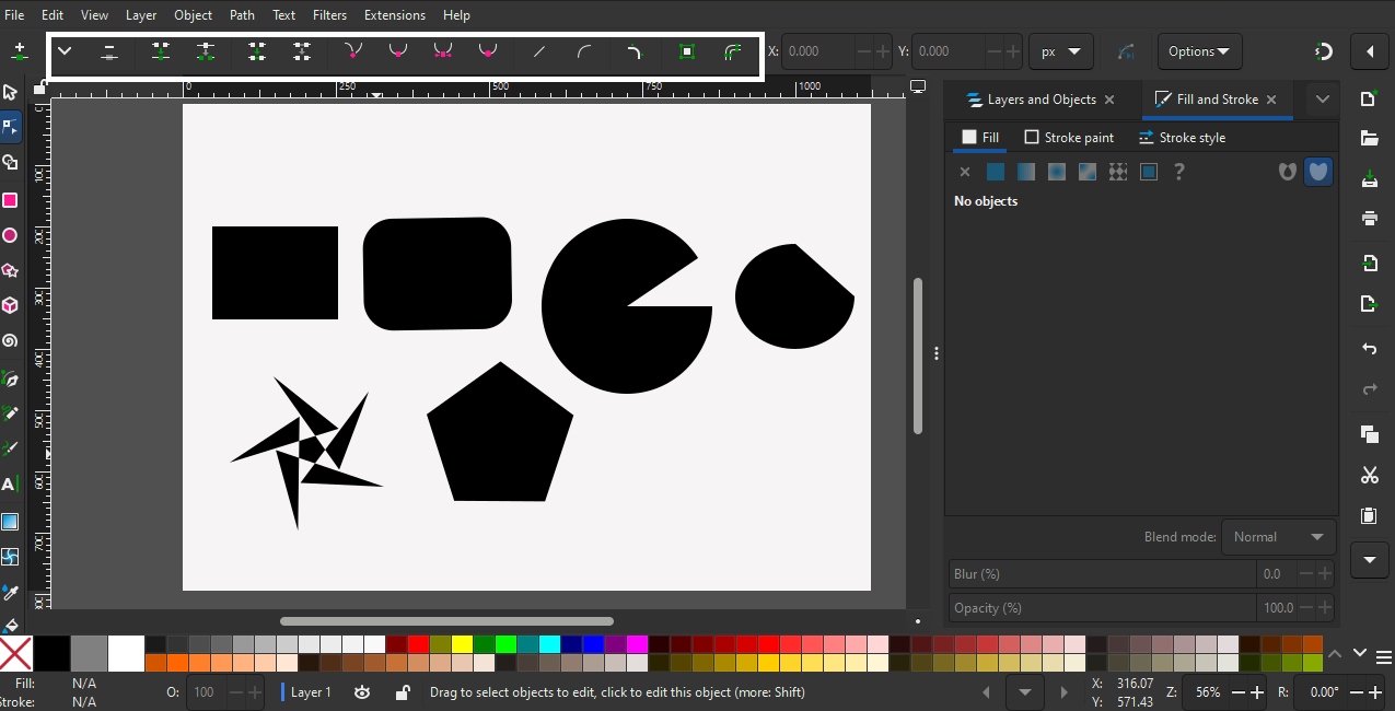
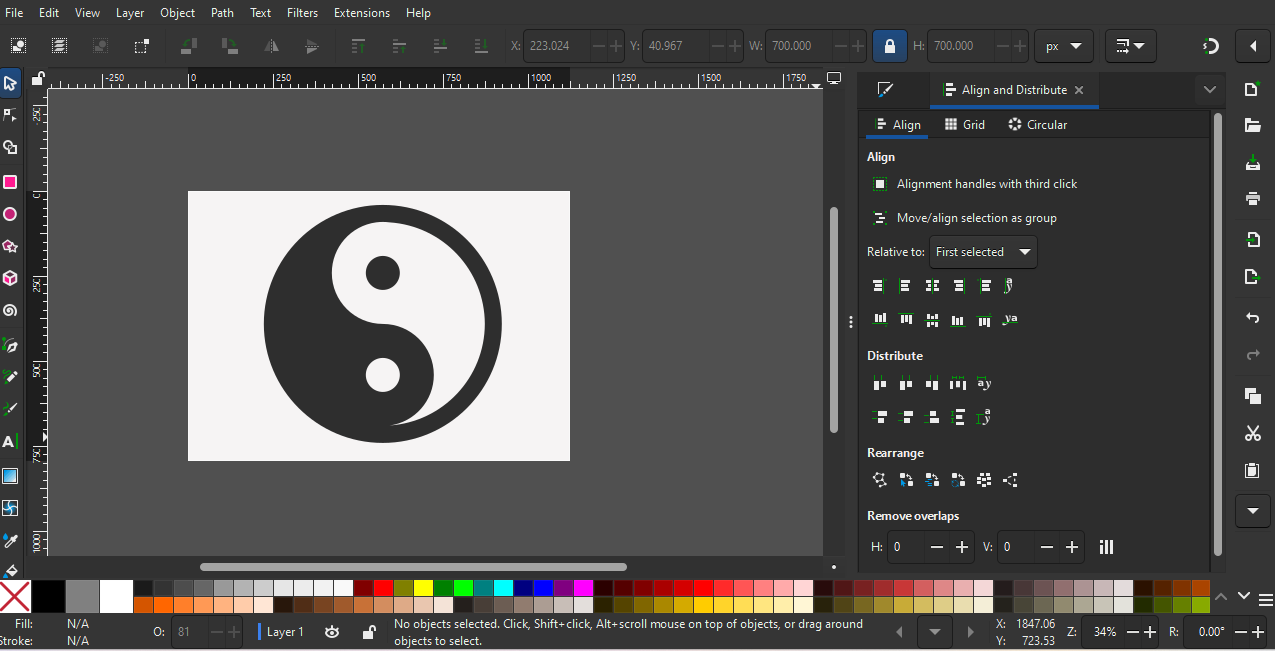
After completing all the settings, the main Inkscape window opened. It has the menu bar at the top, tool options on the left side, and shortcut options on the right side, as marked in the image,
At the bottom of the window, there is also a color palette.
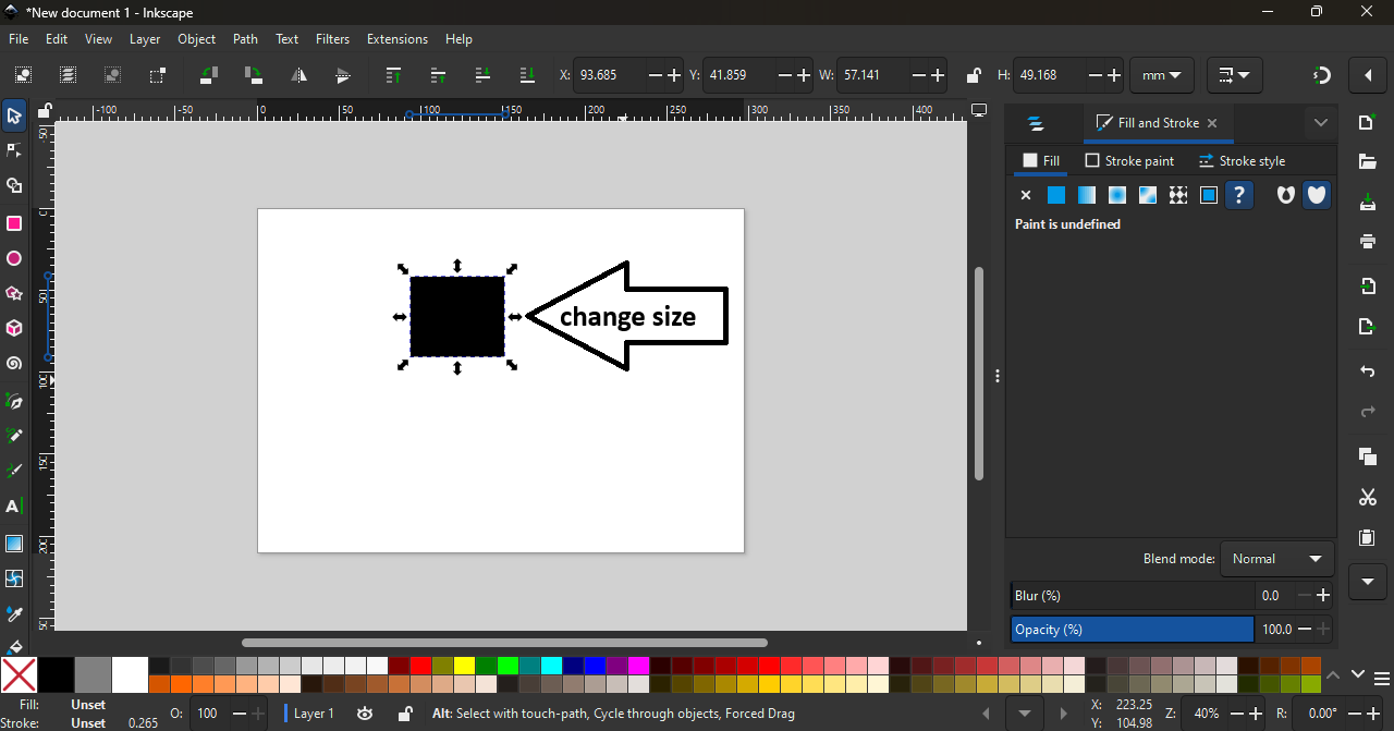
I used the Rectangle tool to draw a rectangle. When I pressed the Ctrl key while drawing, it created a perfect rectangle; otherwise, the shape changed. After creating the rectangle, I used the Selection tool.
Small squares and circles appeared on the border of the rectangle. Using these controls, I was able to change the size and adjust the corners of the rectangle.
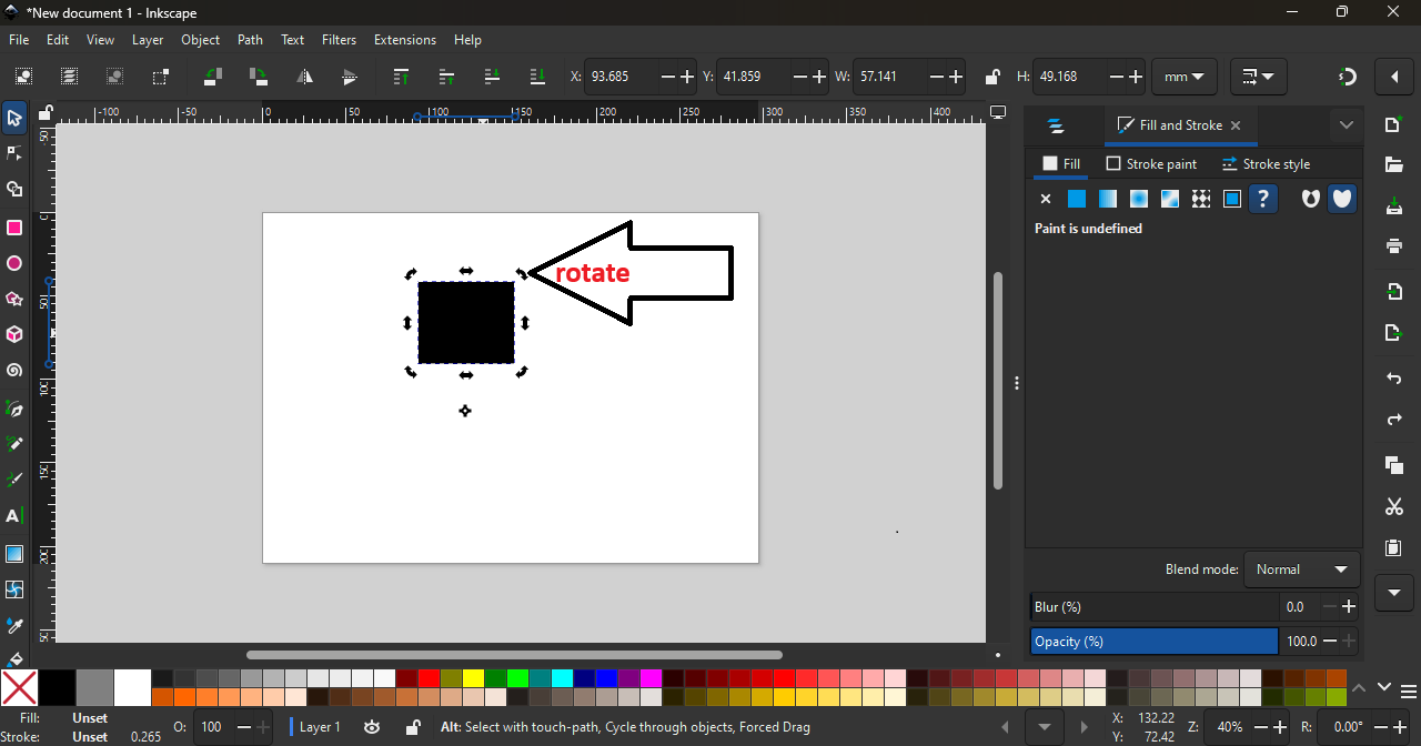
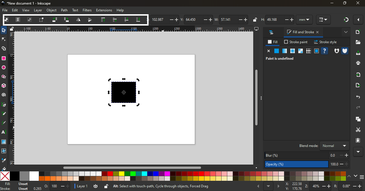
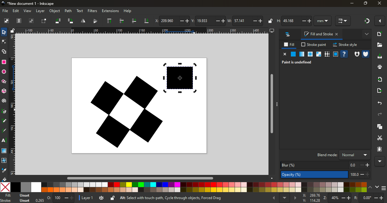
Using the Rectangle tool, I can change the center option of the rectangle. When I press the Ctrl key, the rectangle moves in a straight line from the center. If I rotate the rectangle and press the Space bar, it creates a copy of the rectangle.
I used the Rectangle, Ellipse/Arc, and Star/Polygon tools in Inkscape. Using these tools, I created some basic practice designs. While using these tools, new features and options opened up, which helped me understand how to modify shapes and explore different design settings.
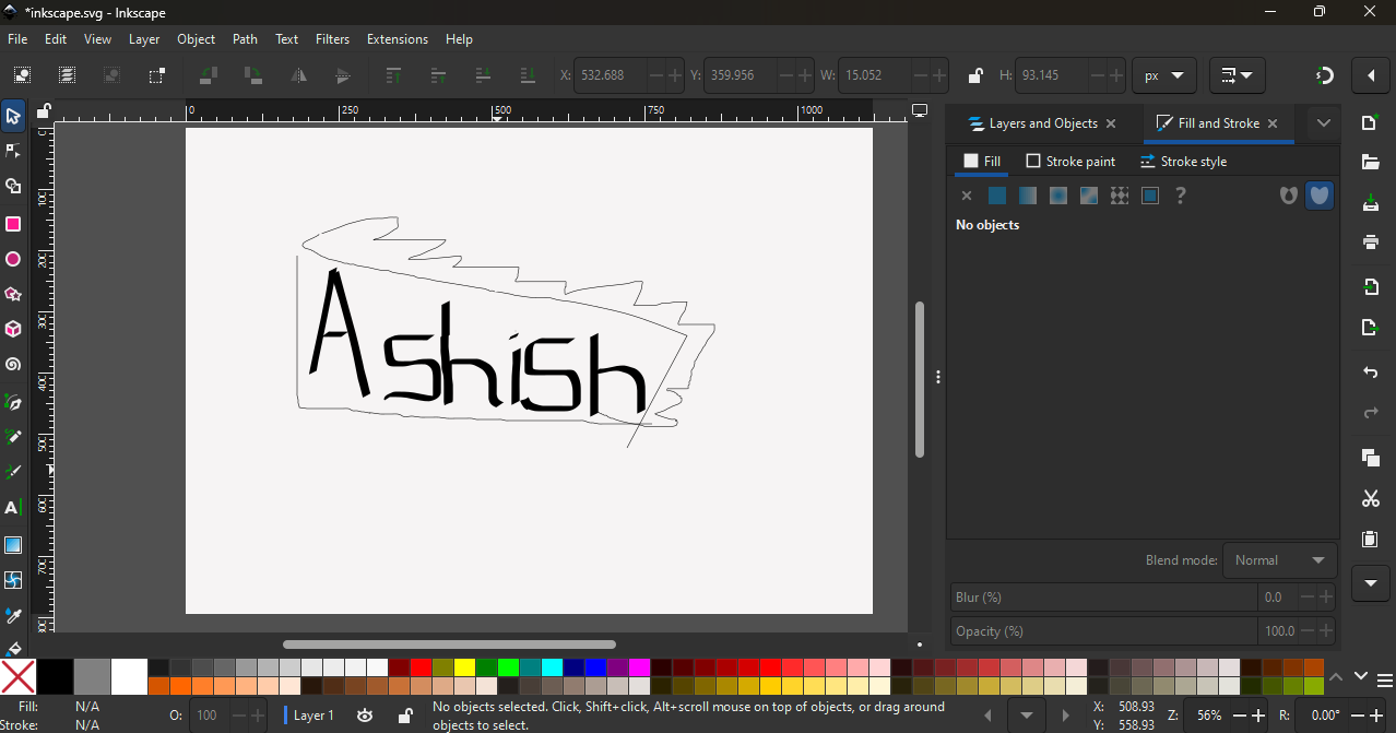
Next, I explored the Pen, Pencil, and Brush tools to draw freehand shapes and paths.
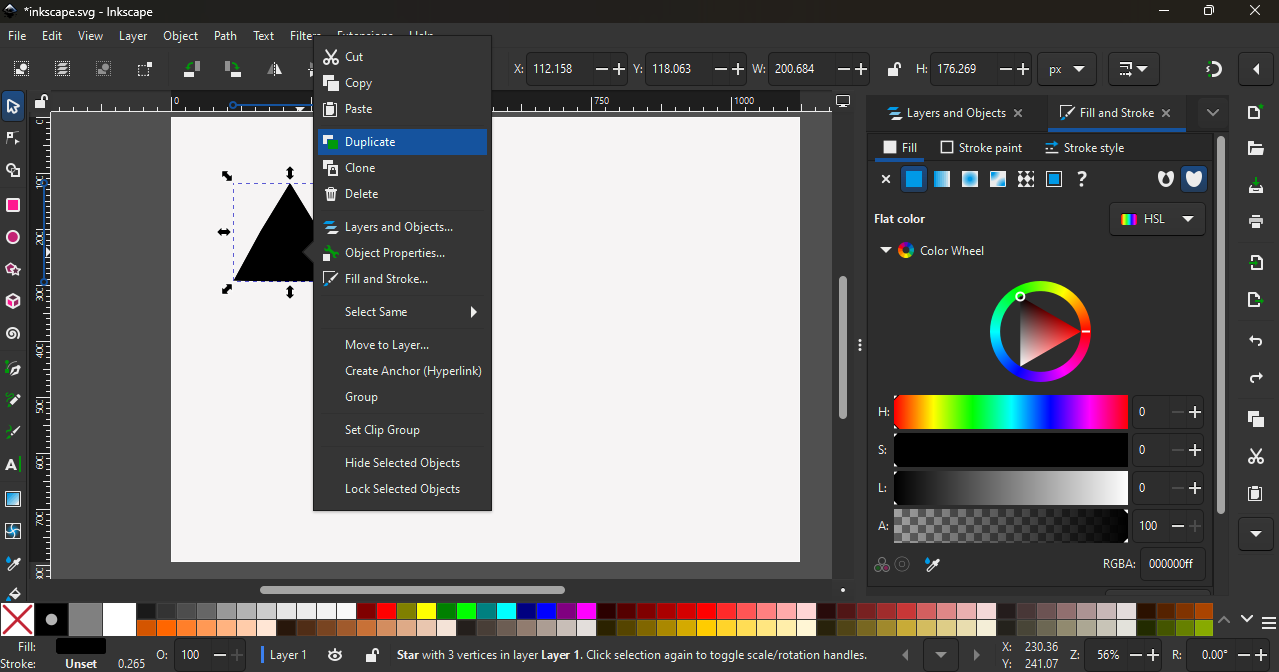
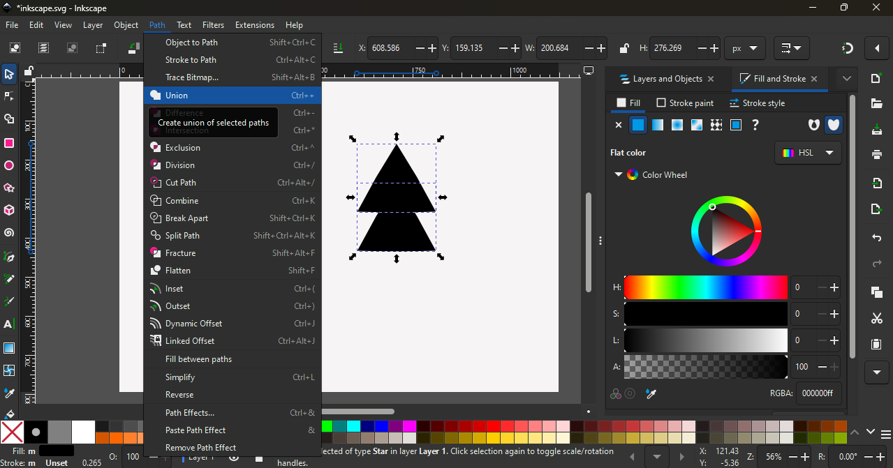
Next, I used the Union tool. First, I selected the Star tool and set it to 3 corners to create a perfect triangle. Then, I right-clicked and chose Duplicate to create another triangle. I placed the second triangle below the first one. After selecting both triangles, I went to Path and chose the Union option to combine them into a single shape.
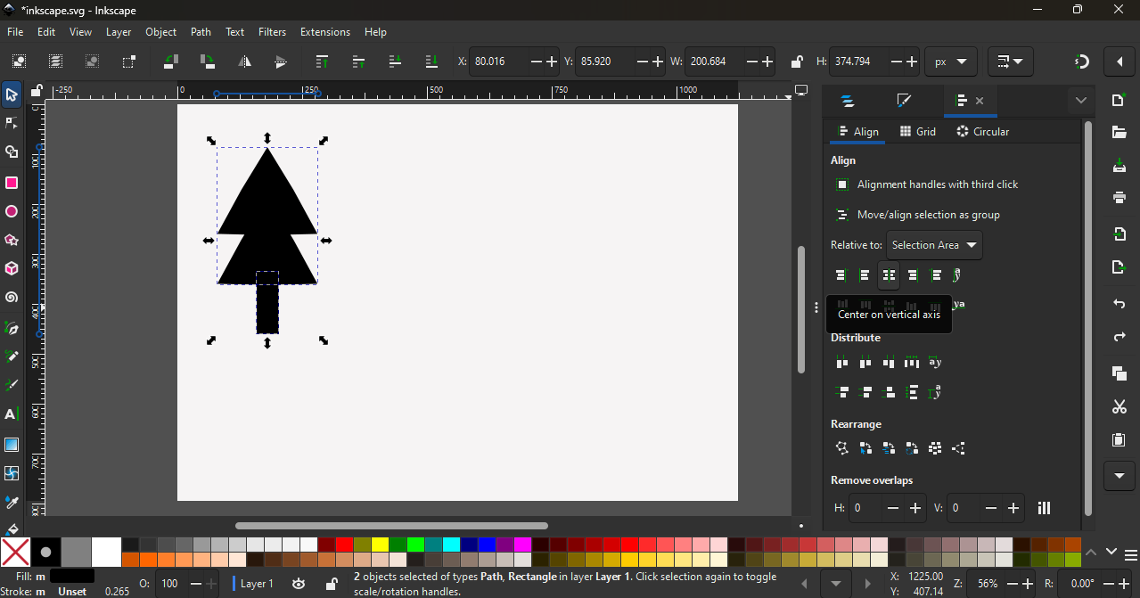
I created a small rectangle and used the Align tool to align it with the double triangle shape, which formed an X-mas tree shape.
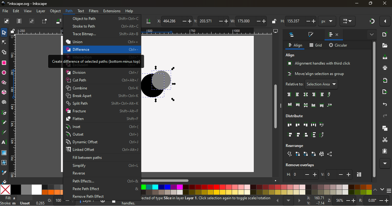
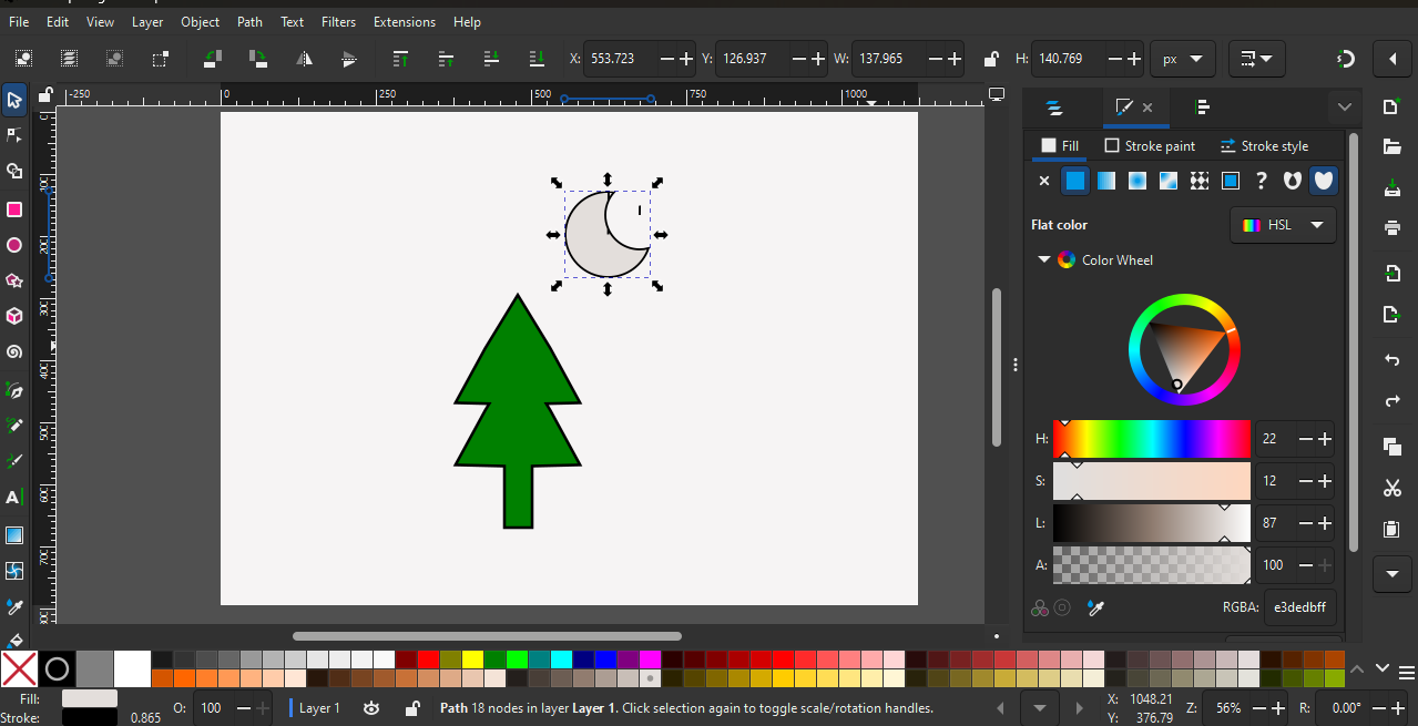
I also used the Difference tool by creating two circles—one circle slightly inside the other. After selecting both circles, I applied the Difference option to cut one shape from the other.
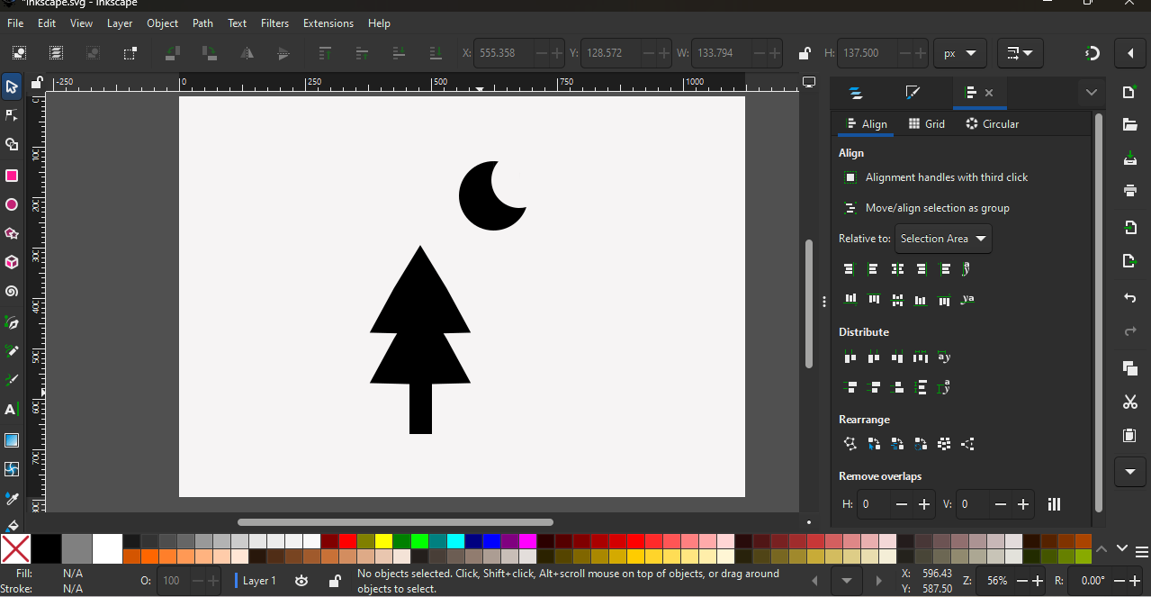
Using these tools, I created an X-mas tree and a half-moon shape
In the last step, I used the Fill and Stroke options to apply colors and adjust the stroke of the shapes.
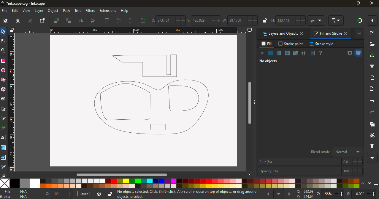
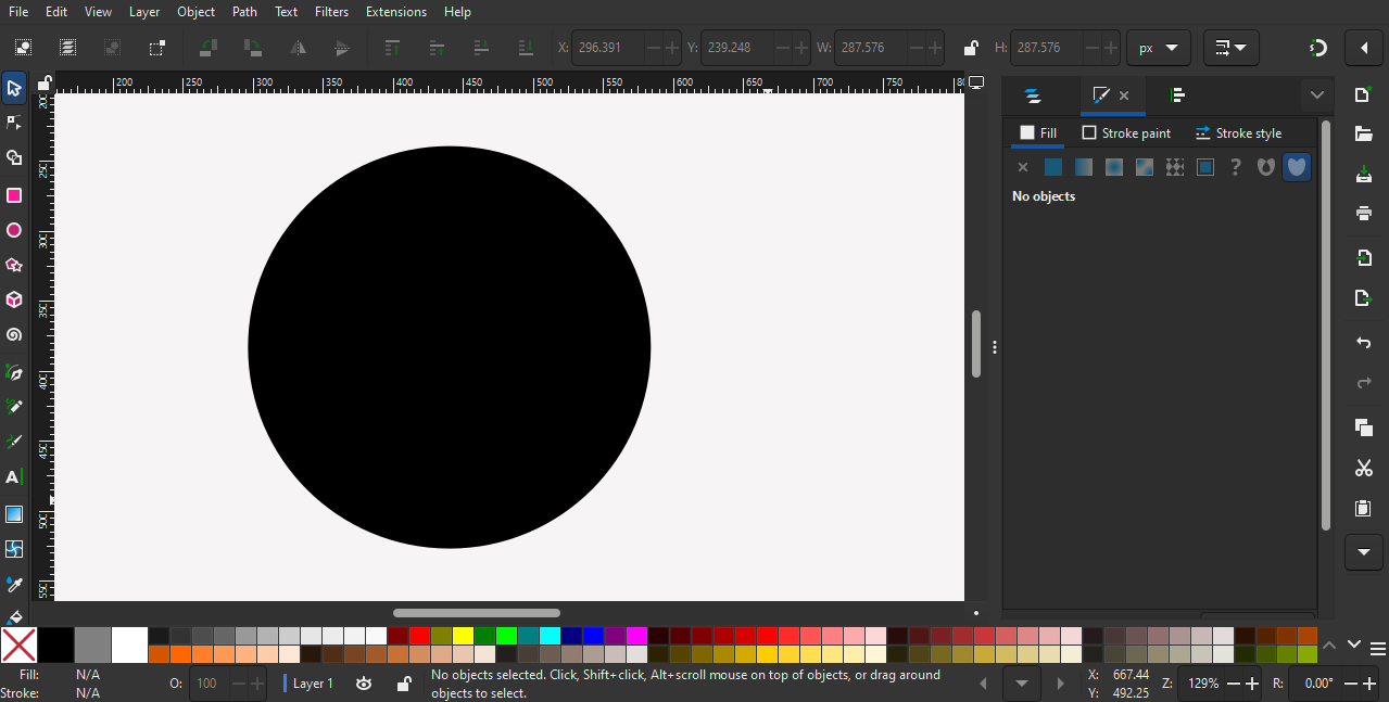
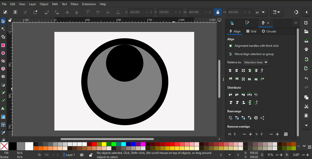
After practicing the tools, I tried to create a small logo. For this, I selected the circle shape.
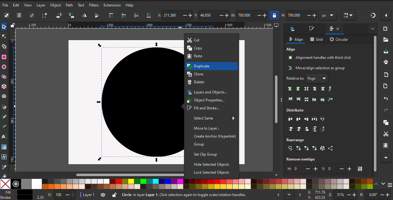
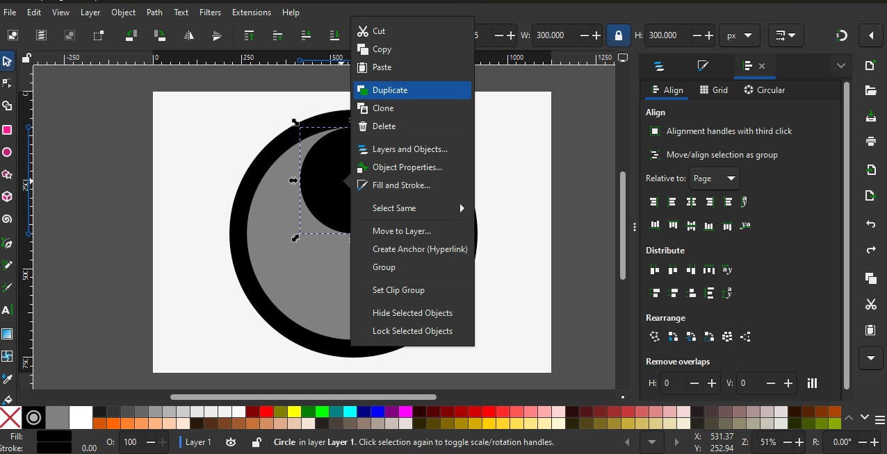
In the next step, I duplicated the shape, changed its size, and aligned it to the center both vertically and horizontally.
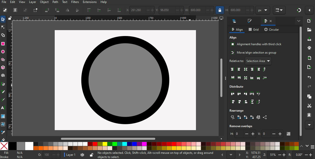
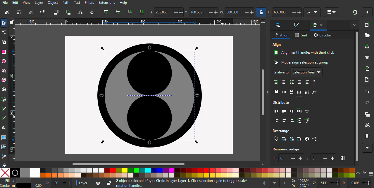
I repeated the same process by duplicating the shape and changing its size. Then, I aligned the smaller circles to the top and bottom of the inner circle.
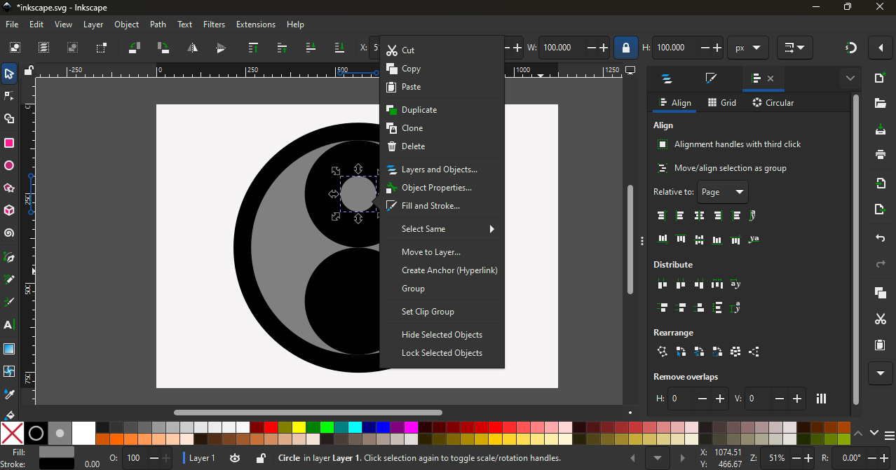
I followed the same process again by changing the size and aligning the shape to the center inside the circle.
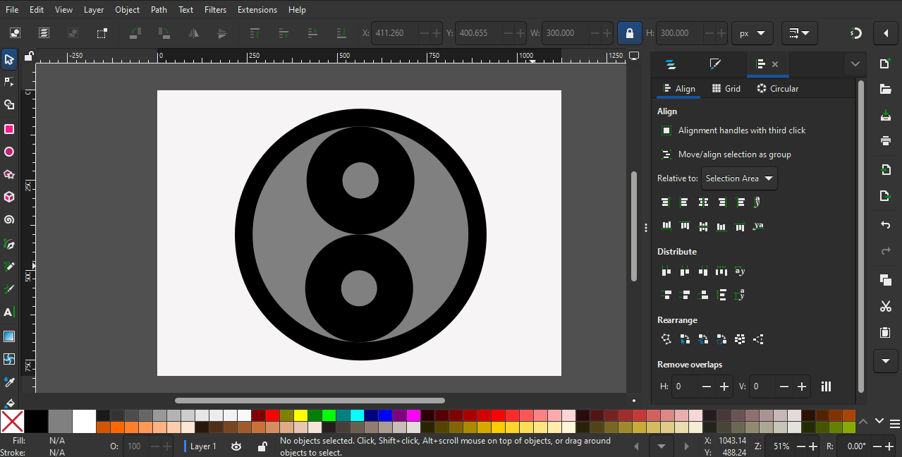
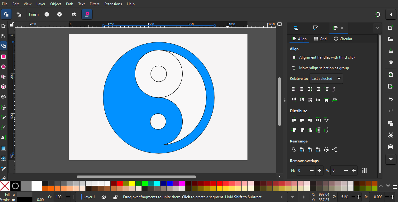
In the next stage, I used the Shape Builder tool to combine the shapes and complete the design.
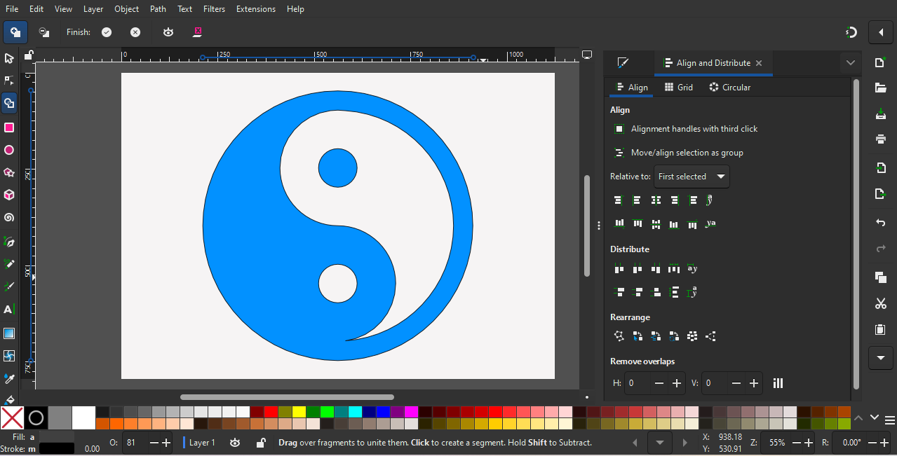
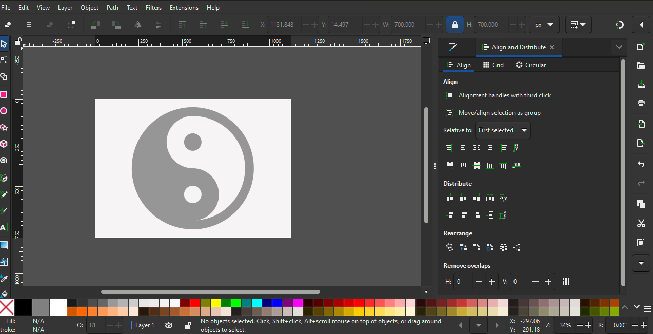
The final output of the logo design looked like this.
GIMP
GIMP is an open-source software. It can be downloaded from the official website using this link:
https://www.gimp.org/downloads/
GIMP is used for photo editing and working with raster images.
For example, GIMP can be used to crop images, resize photos, adjust brightness and contrast, remove background, add text on images, and apply filters and effects.
It is commonly used for editing photographs and preparing images for websites and documents.
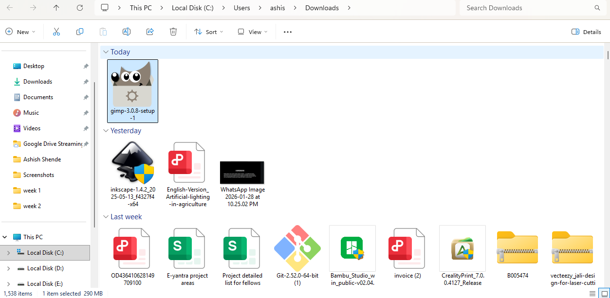
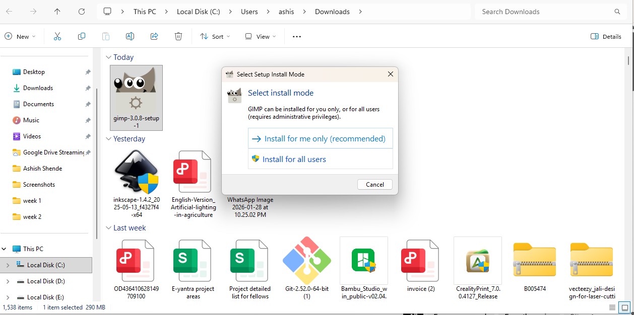
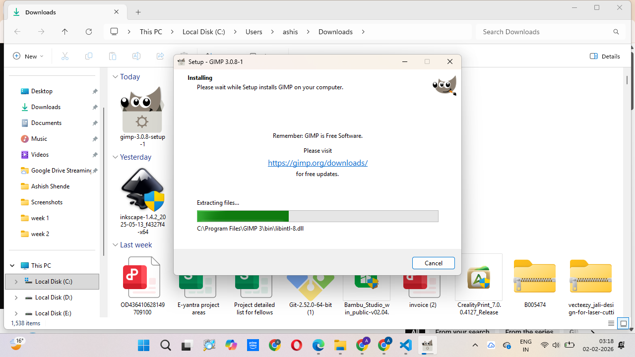
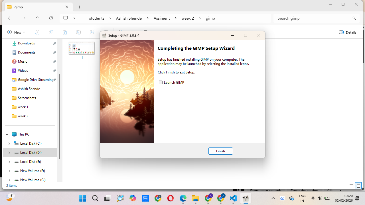
After downloading the file, I clicked on it and installed the software on my system.
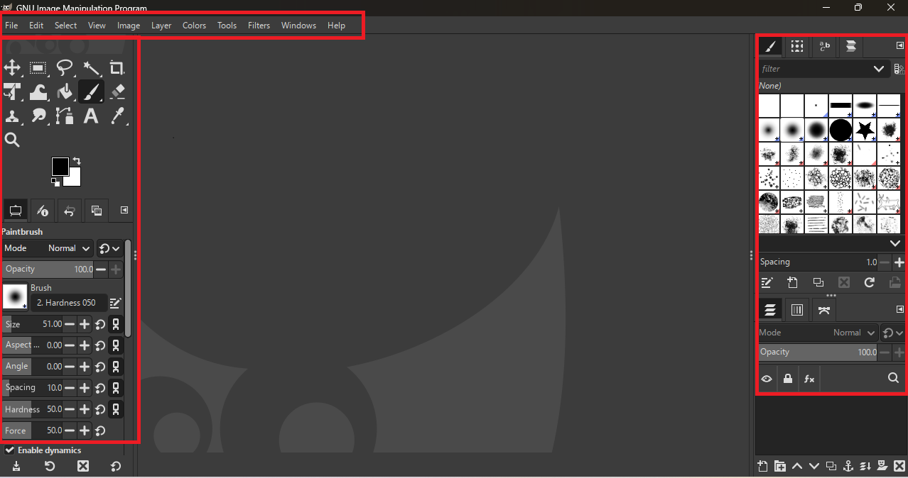
After opening the software, the window shows a menu bar at the top, a tool bar on the left side, and shortcut tools and dialog boxes on the right side.
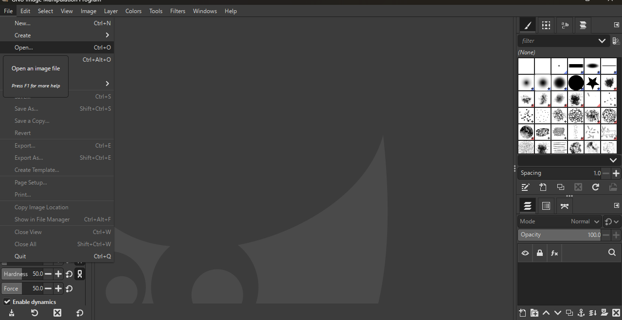
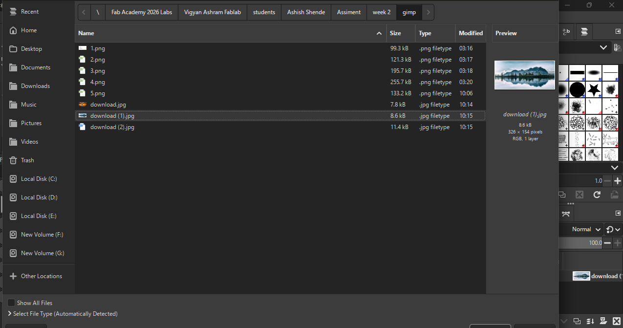
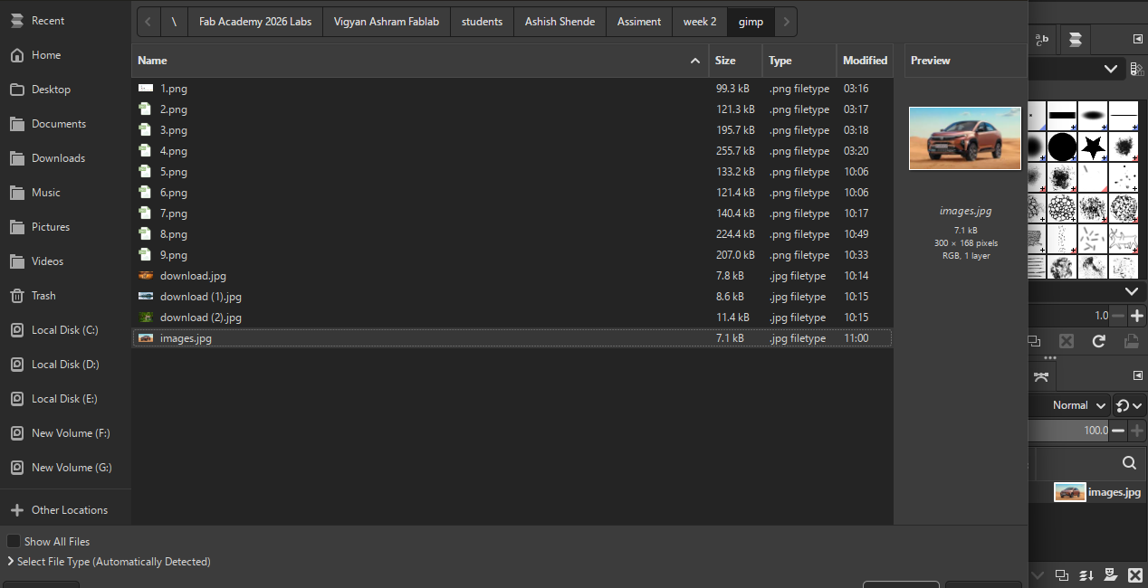
Next, I went to the File option, selected Open, chose the folder I wanted, and opened my image.
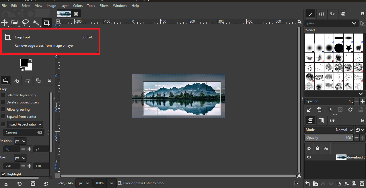
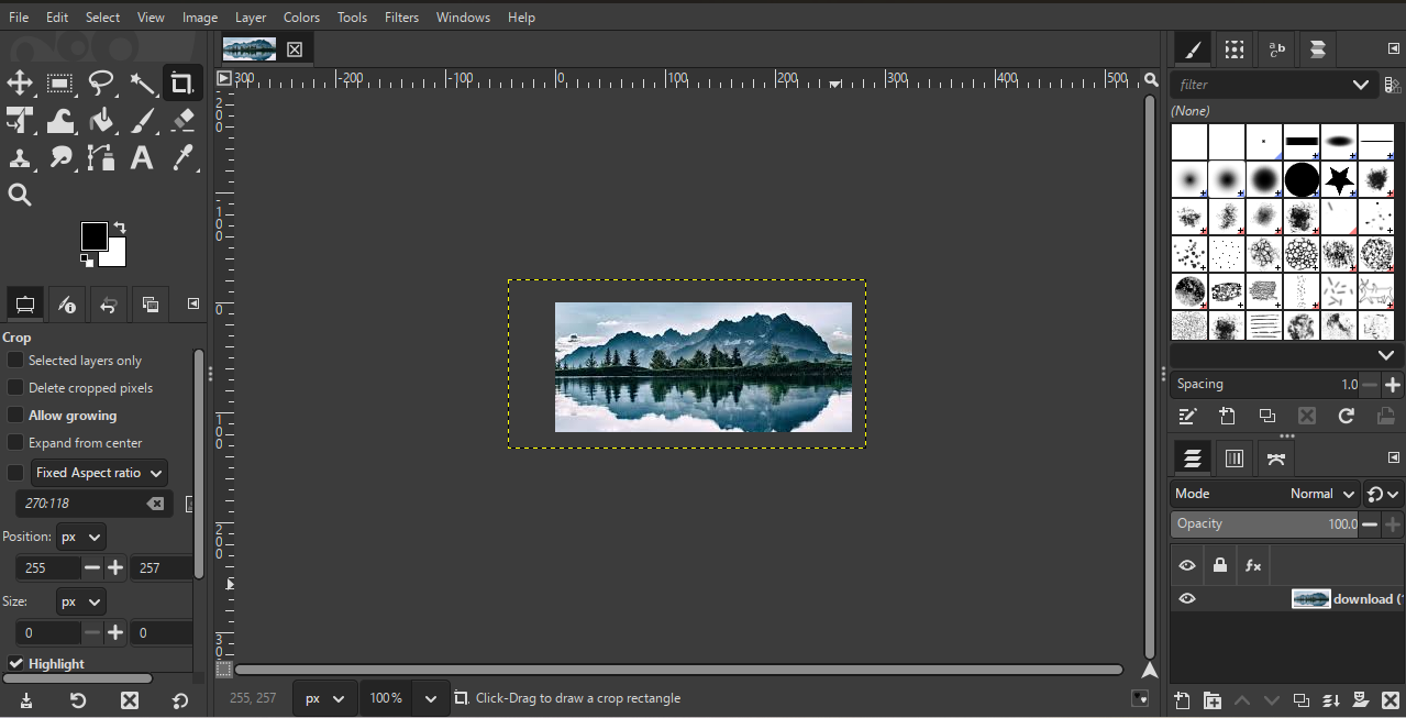
In GIMP, my first task was to learn how to crop an image. I went to the left side toolbar and selected the Crop tool. Then, I clicked on the image, pressed and held the mouse button, and
selected the area I wanted to keep. After selecting the area, I double-clicked on the image, and the image was cropped successfully.
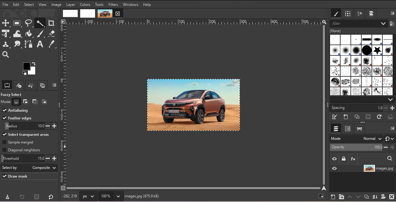
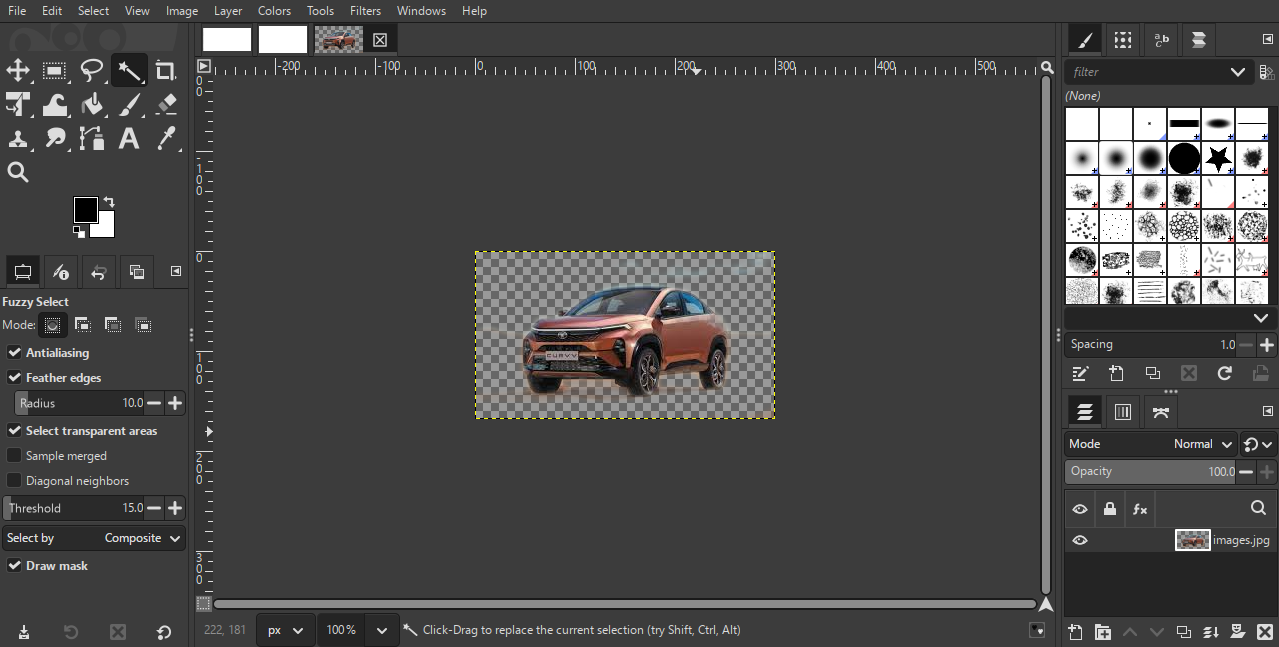
Next, I wanted to change the background color in GIMP. For this, I selected a new car image from my folder and opened it in GIMP.
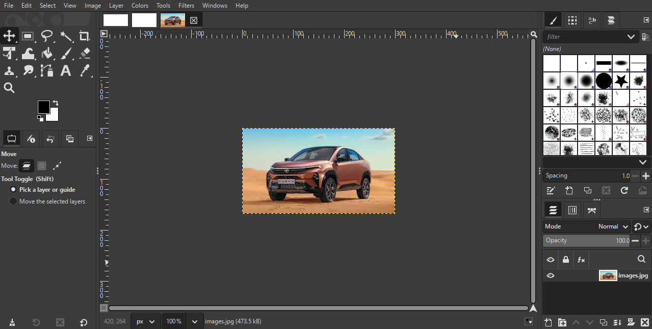
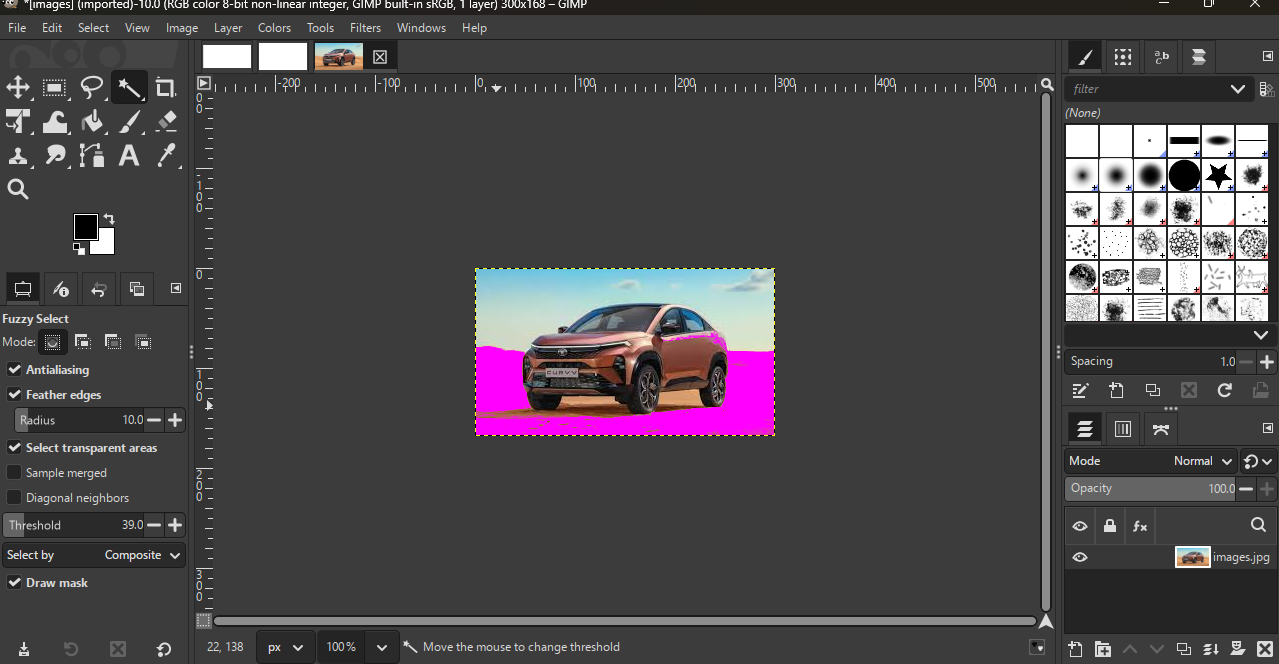
Next, I went to the right side and used Alpha to Selection. Then, I selected the Fuzzy Select Tool, clicked on the area of the image I wanted to remove, and deleted the selected part.
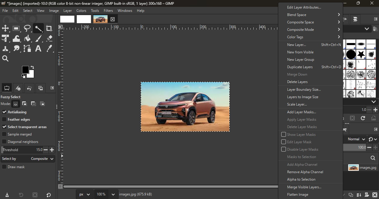
Next, I went to the right side and used Alpha to Selection. Then, I selected the Fuzzy Select Tool,
clicked on the area of the image I wanted to remove, and deleted the selected part.
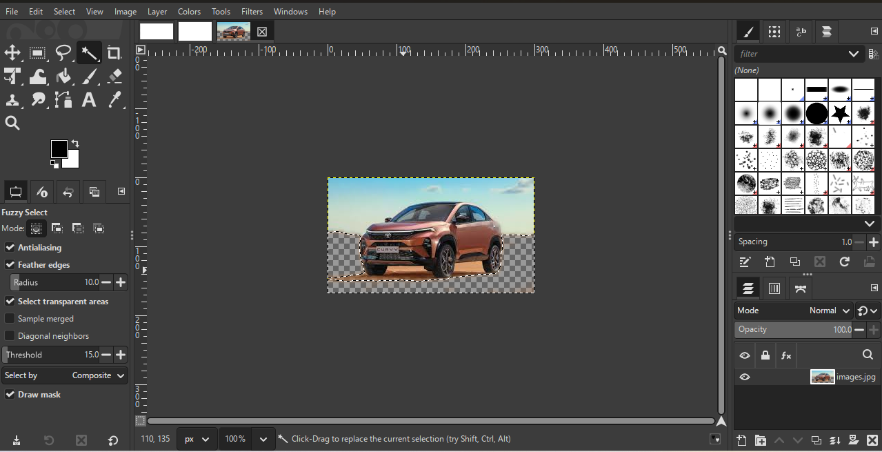
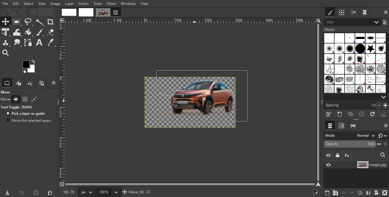
After deleting all the selected parts, the final result appeared Then, I selected the image and moved it to the required area.
The following links were used as references during this assignment to dwonload images:
• https://www.69dropsstudio.co.uk/blog/nature-photography-types/
• https://zeenews.india.com/photos/auto/big-upcoming-car-launches-this-festive-season-tata-mg-kia-2785429
3D software
Why I'm choose the this software
I chose solidworks and fusion 360 sofware for 3d molding because both of these software are widely used in the industry for the product design and mechine modling. solidwork is a powerfull software that allows me to create detailed and accurte 3d models
with ease. it has a user friendly interface and a wide range of tools and features that make the desgin process efficient and effective.
fusion 360 is also a greate software that provides a clean and in tuitive interface which makes its easy to learn and use. fusion360 also provides student version which is free for the students and educators, so its a cost effective opportunity for me to learn and use this software.
its also a cloud based software wchich allows for easy collaboration and access to my designs from anywhere. bothse are in
industry standaed software that are widely used in the filed of product design and mechine modeling, so lering these software will give me a strong foundation in 3d modeling and help me in my feuture projects and career in the field of product design and me chine modeling.
In this assignment, I learned 3D modeling using SolidWorks software. SolidWorks is a powerful, industry-level tool that is widely used for product design and mechanical modeling. It helps designers clearly visualize products in a realistic 3D form before they are manufactured. One of the best things about SolidWorks is that it allows us to change design parameters easily. If we want to modify the size, shape, or dimensions of a part, we can simply edit the values and the model updates automatically. This makes the design process faster and more flexible.
Part Design
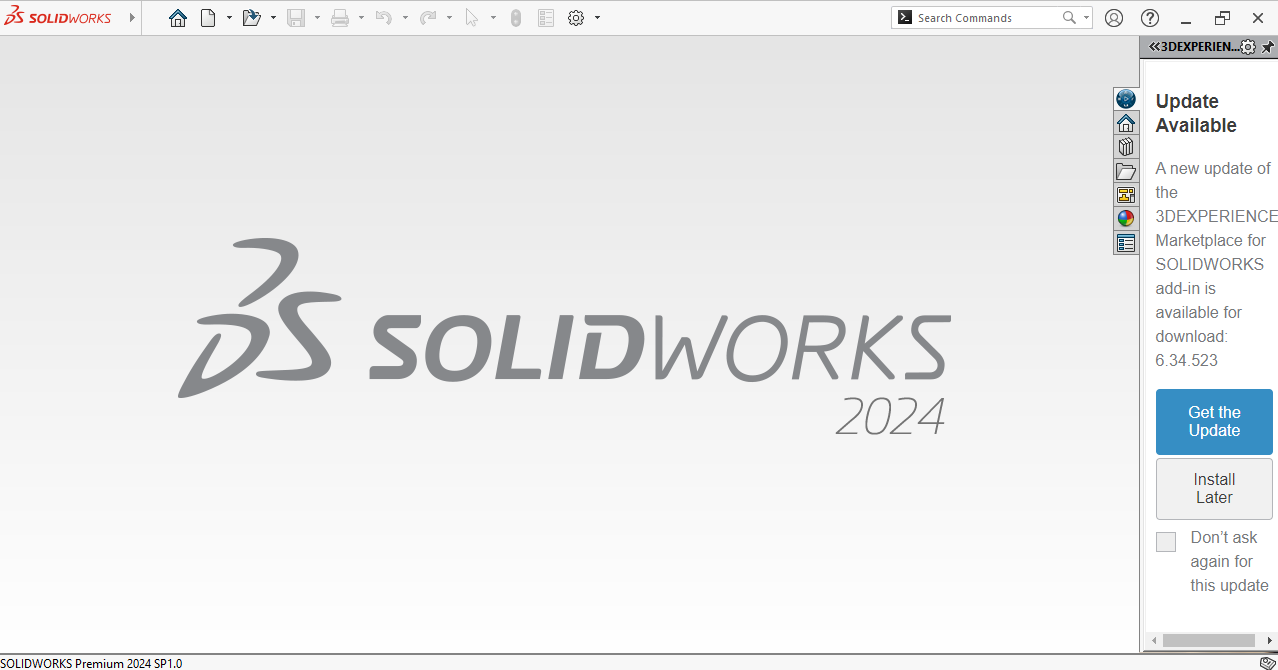
I started using SolidWorks and first understood the home screen of the SolidWorks software.
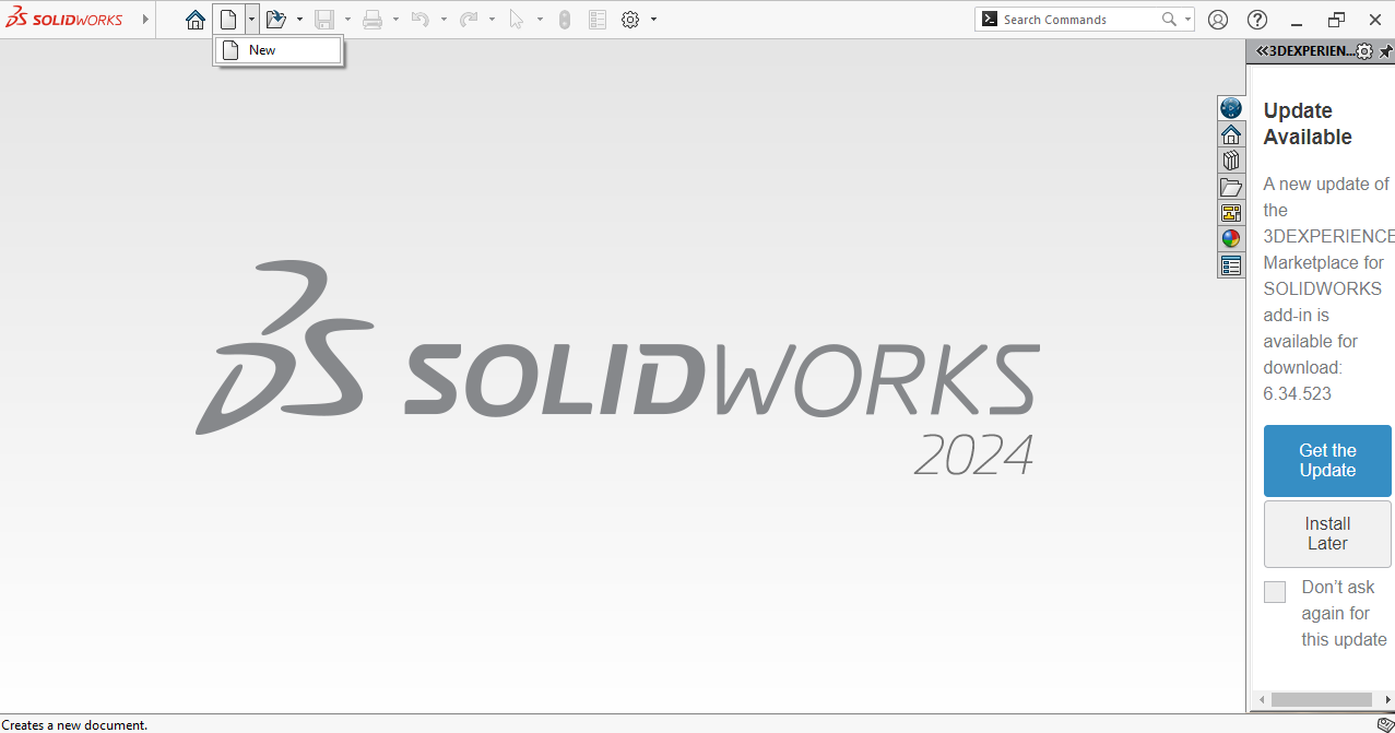
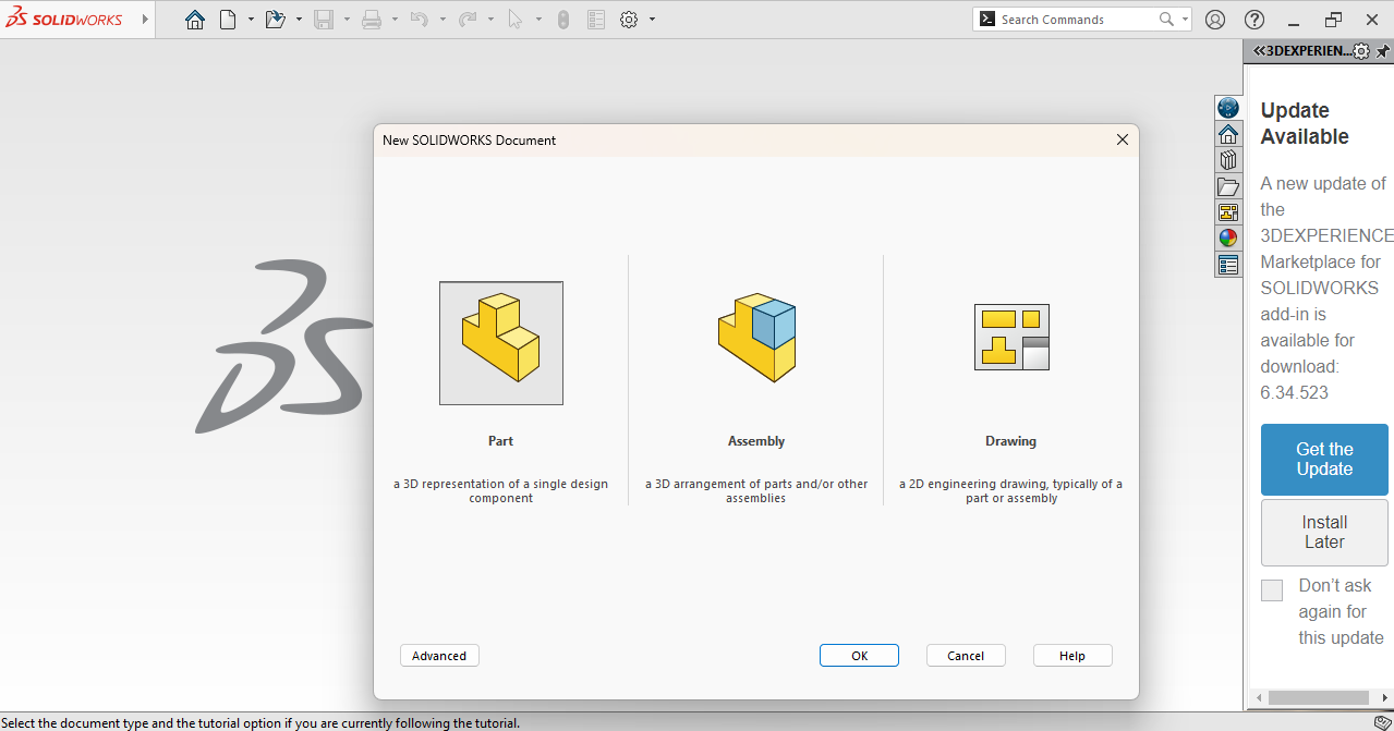
On the top menu bar, I selected New to start a new file.
Then a new window opened, I selected Part and clicked OK.
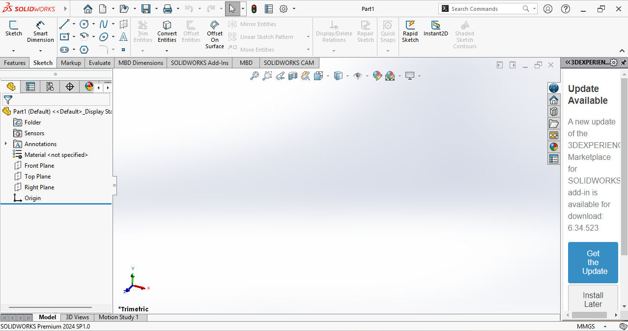
After that, the main working window opened. At the top, there is a navigation bar, below it are selection tools, on the left side I can choose the plane I want, and on the right side there are some shortcut tools.
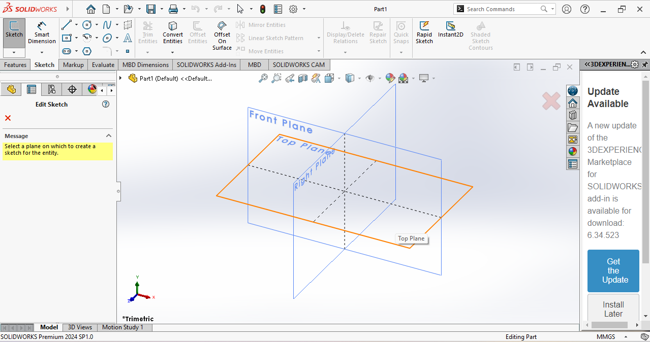
According to my design, I selected the Top Plane.
In the next step, I went to Sketch and selected the Center Rectangle tool with dimensions.
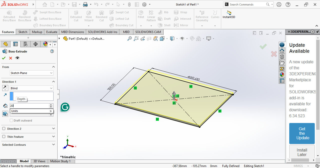
I set the dimensions and then went to the Extrude tool. Using the Extrude tool, the 2D sketch was converted into a 3D design. From here, the actual 3D design part started.
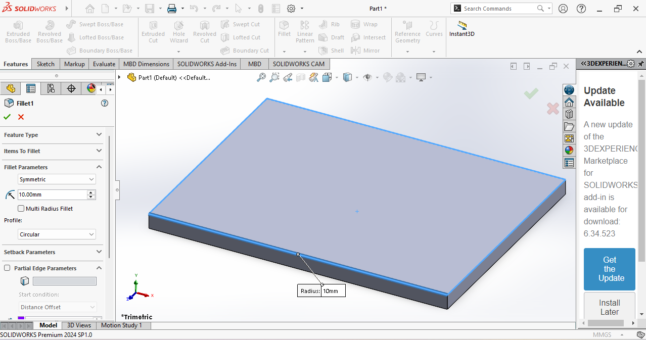
Next, I chose the Fillet tool and applied it to the four top corners to change them into curved shapes.
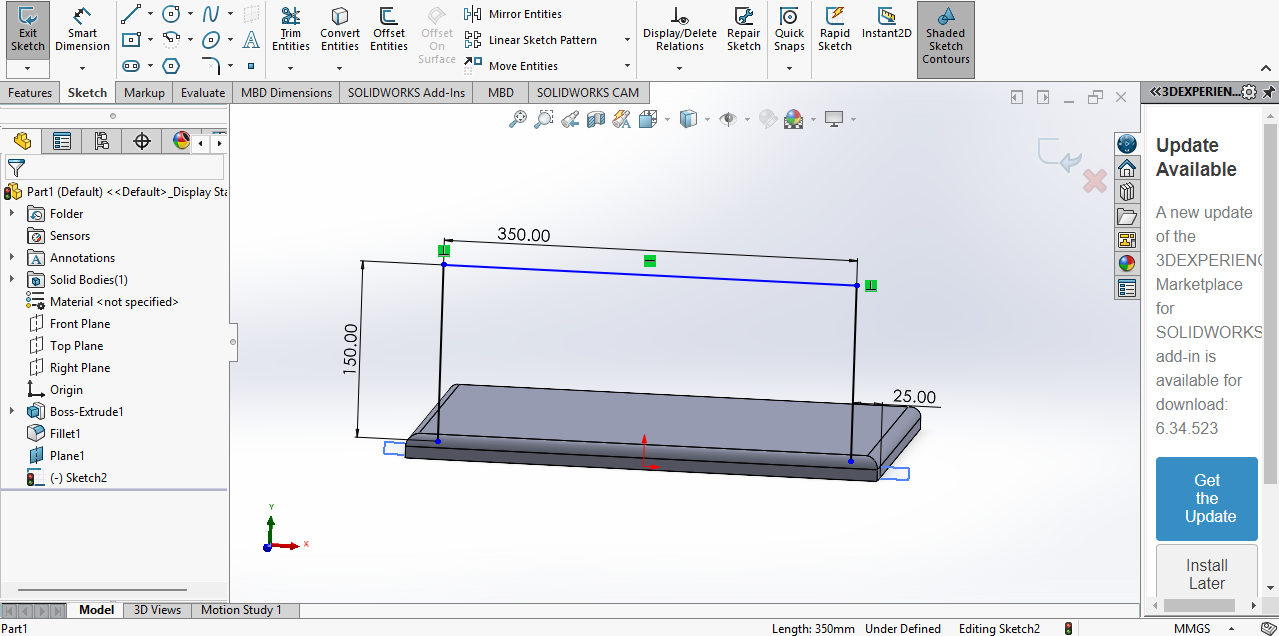
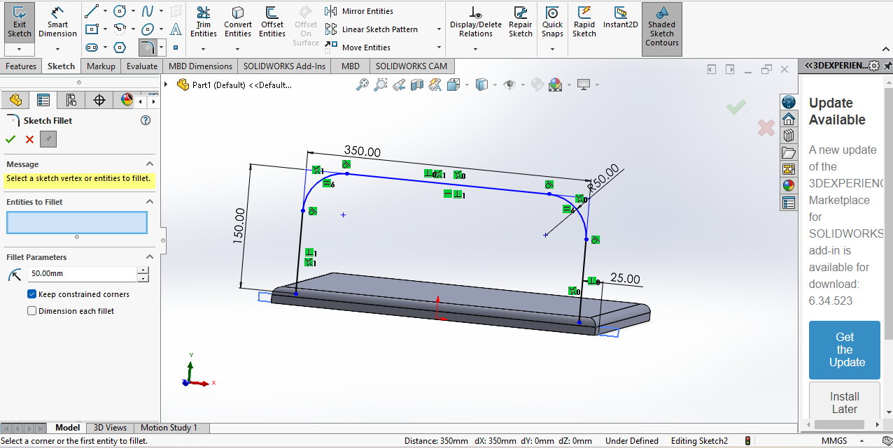
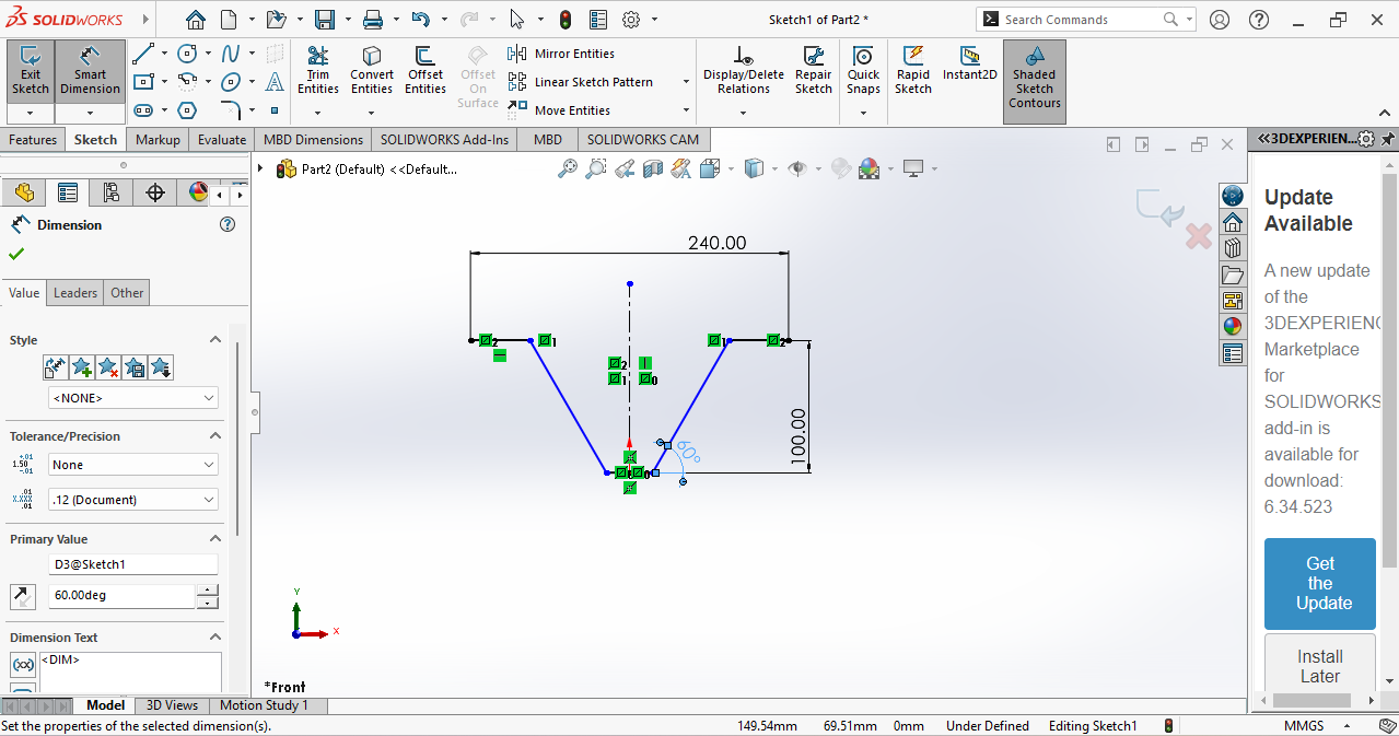
Then I selected the Front Plane and drew a sketch on the body with dimensions, My corner edges were converted into curves using the Sketch Fillet tool
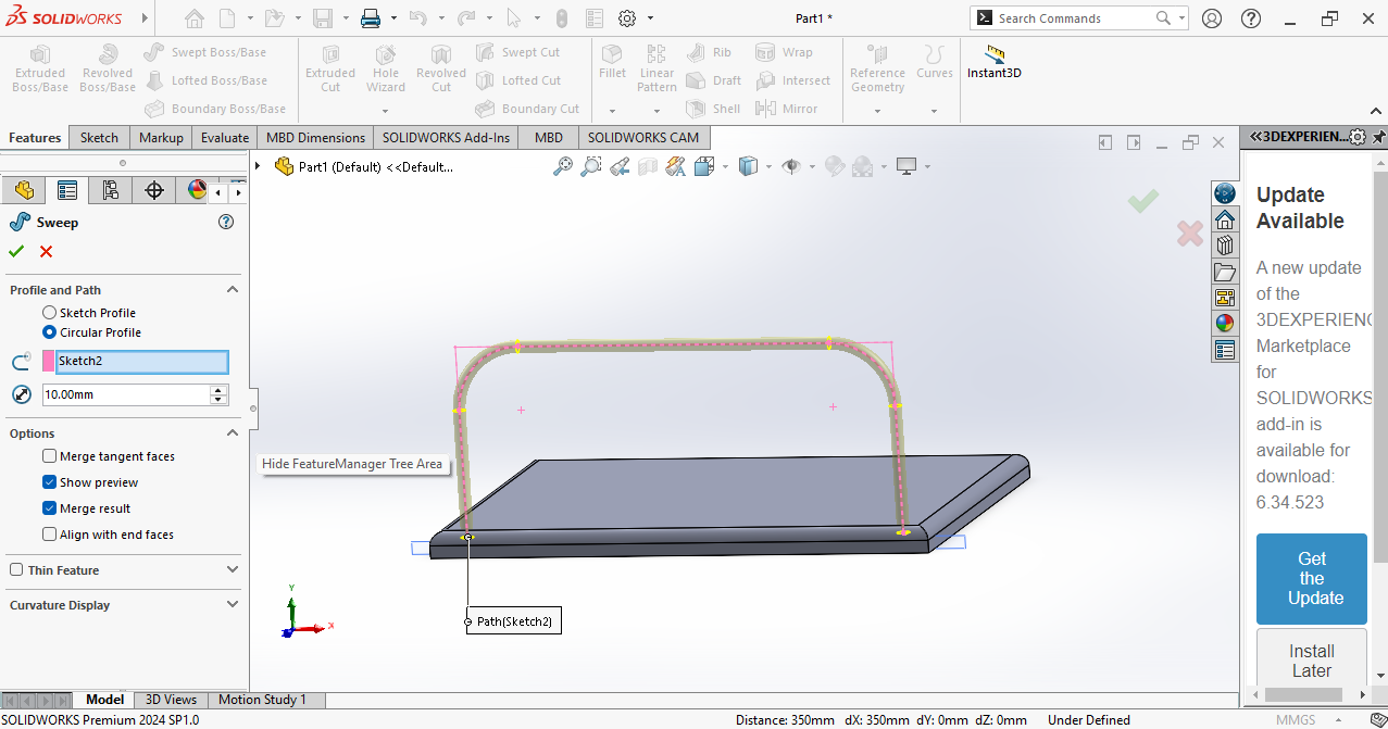
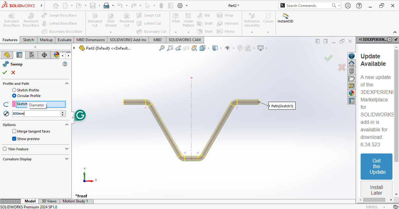
Next, I used the Sweep tool and selected my sketch. This converted the sketch into a pipe.
Then I wanted the same shape on the other side, so I choose the front plane.
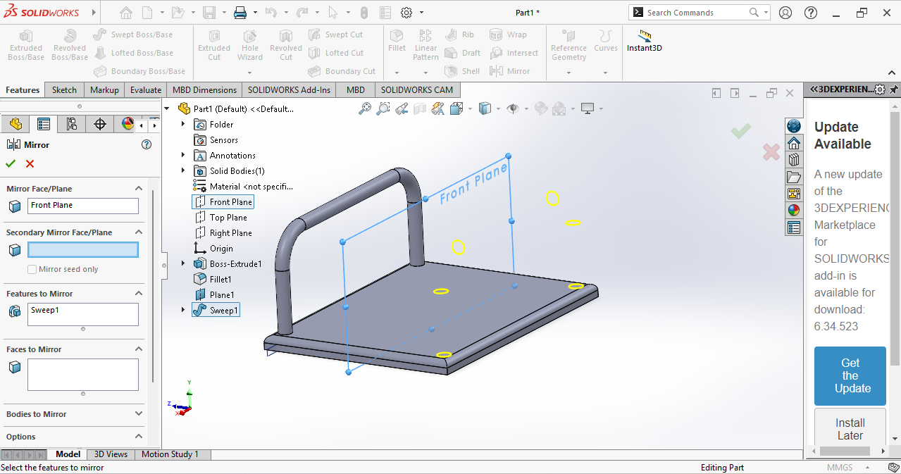
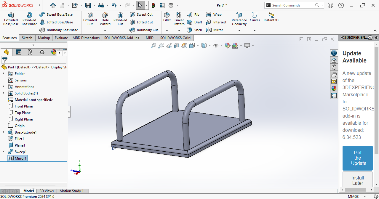
I used the Mirror tool to copy the body to the other side.
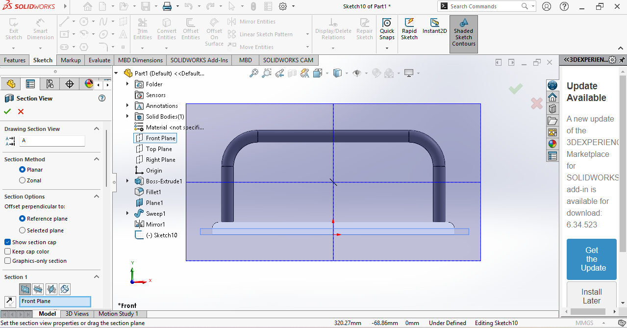
Next, I used the Section View to see the inside of the model.
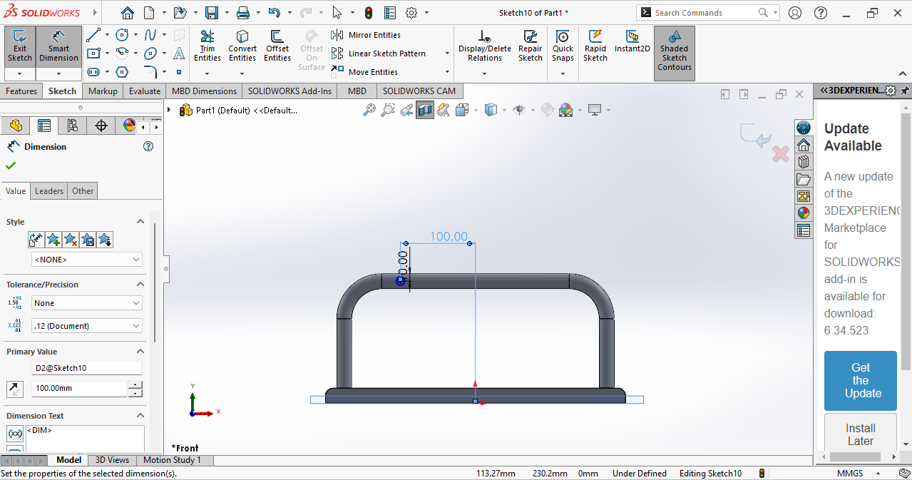
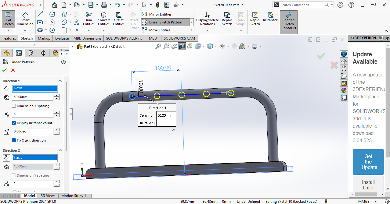
I drew a sketch to make a circle using the Center Circle tool.
Then I needed the same circle in a straight line, so I used the Linear Pattern tool and selected the circle.
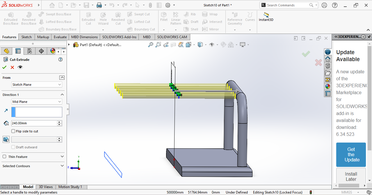
Then I wanted holes in my bar on both sides, so I selected the circles and used the cut Extrude tool.
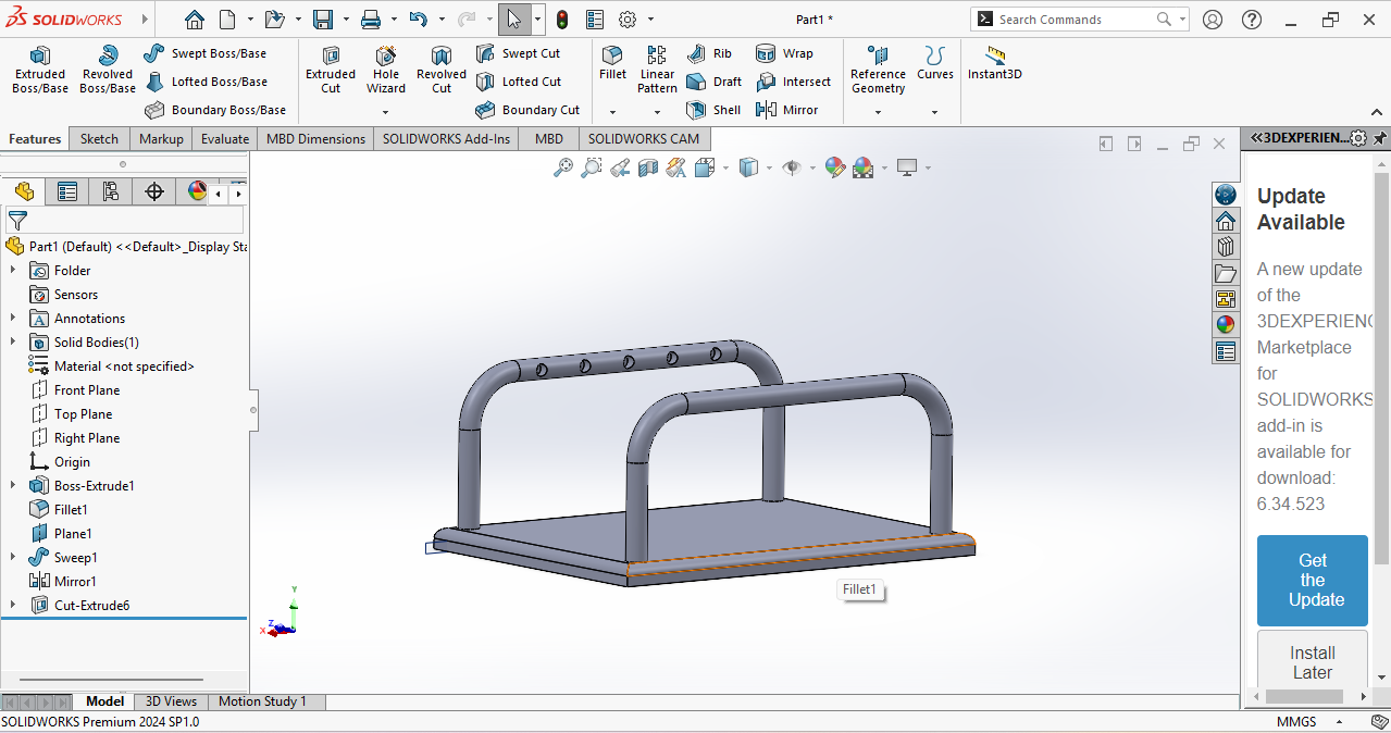
Then my first part was ready and looked like this.
After my first part was ready, I worked on my second part. Again, I selected New File, chose a plane, and drew a sketch.
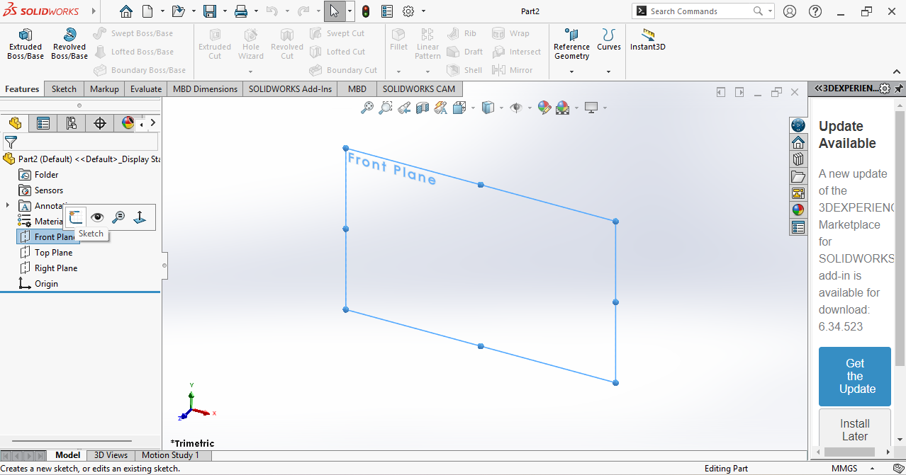
I used the Line tool to draw a sketch and added dimensions.
Again, I used the Sweep tool.
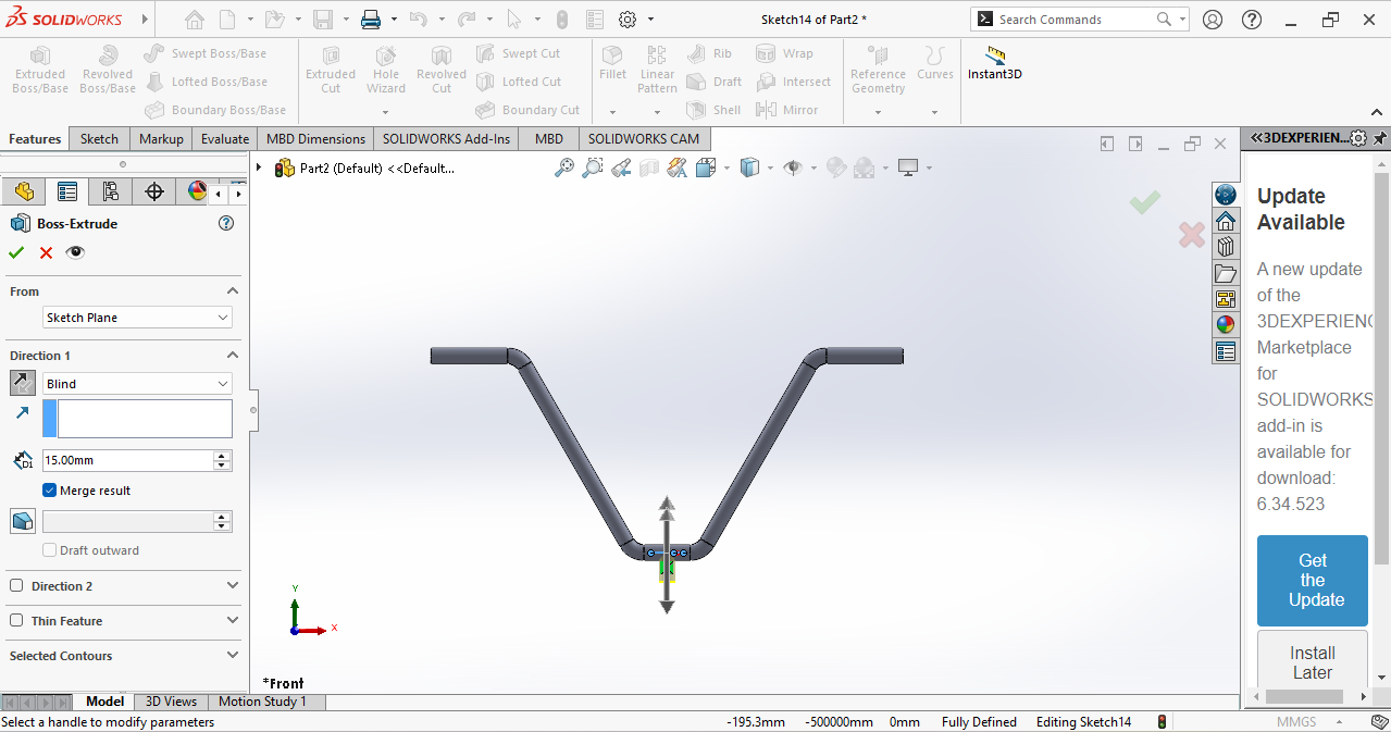
And skech on top plane and Extrude
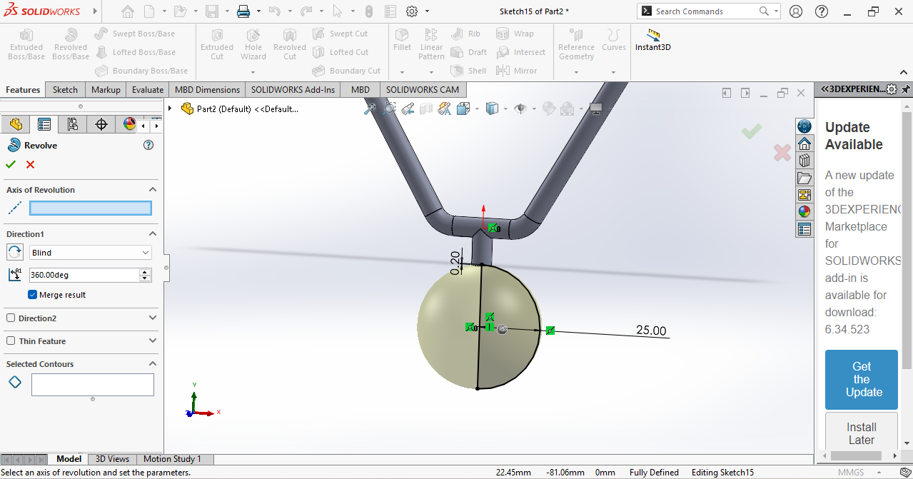
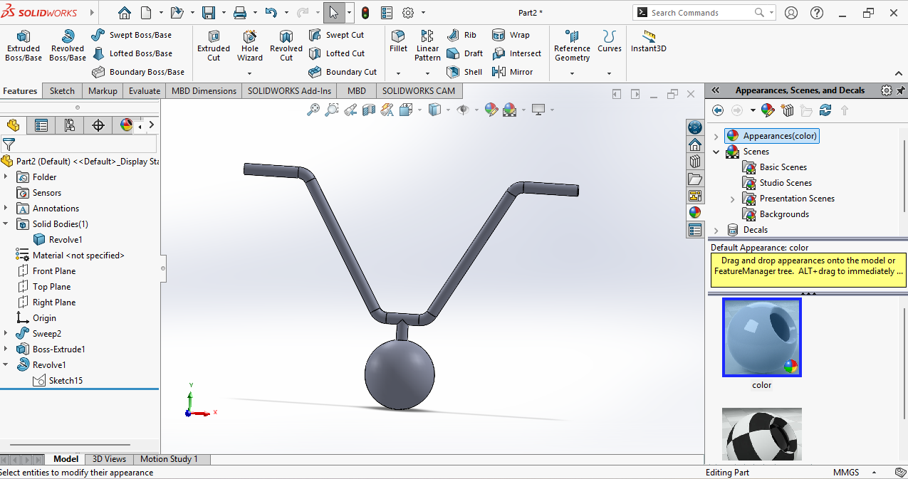
I needed a round ball, so I created a half-circle sketch and used the Revolve tool.
Now my second part is ready.
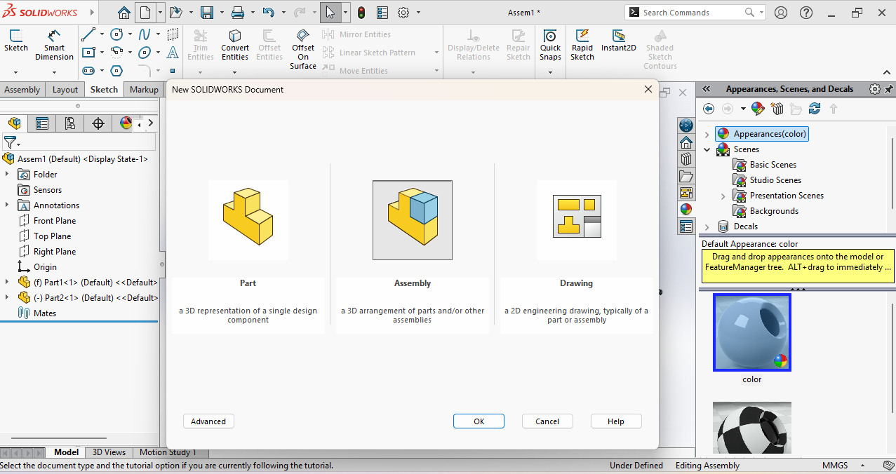
Assembly
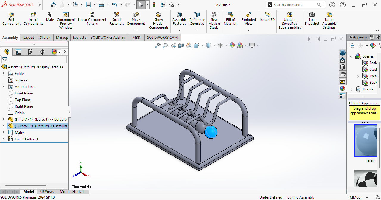
Next, I joined the two parts in the Assembly section. For this, I went to New File and selected the Assembly option.
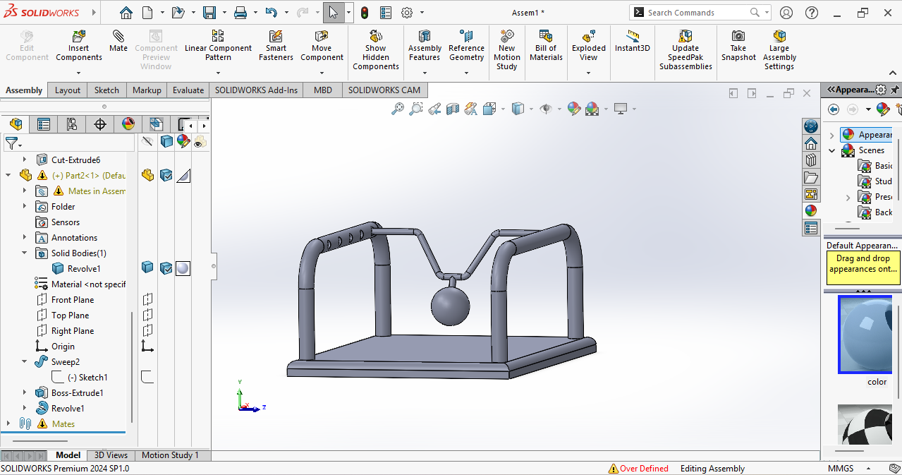
In the Assembly, I opened both parts and joined them using the Mate tool.
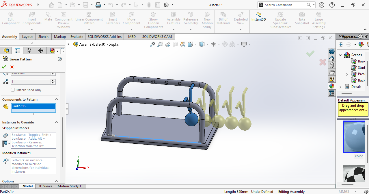
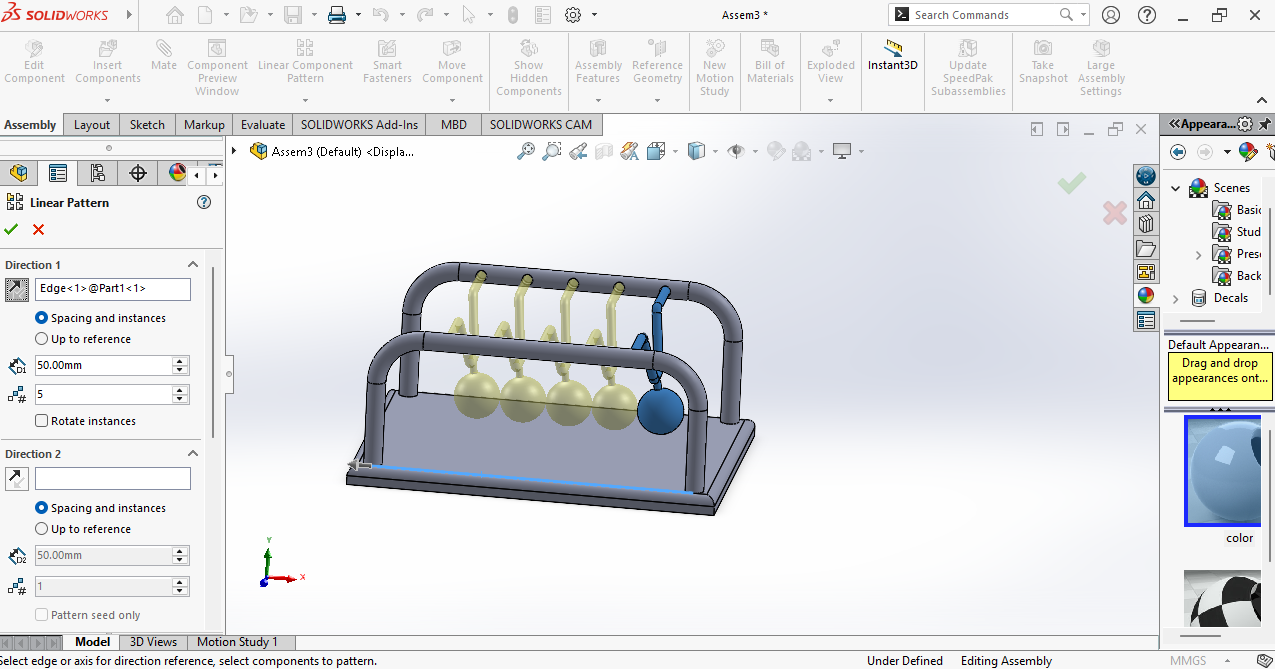
According to my design, I needed 5 copies of Part 2, so I used the Linear Pattern tool.
I joined all the parts together using the Mate tool.
Motion
the next step, I wanted to create motion, so I went to the Motion tool.
Here is the video showing the final motion.
Reference
I used this video to learn SolidWorks:
https://www.youtube.com/watch?v=0JIR2Zmc3u8
Fusion 360
Fusion 360
I also tried another 3D modeling software called Fusion 360, which is widely used in professional product design.
Fusion 360 provides a clean and user-friendly interface, which made it easy for me to learn and adapt quickly.
The software allows both parametric modeling and 3D visualization, making the design process flexible. While using Fusion 360,
I explored basic modeling tools and understood how it is used in real-world product development.
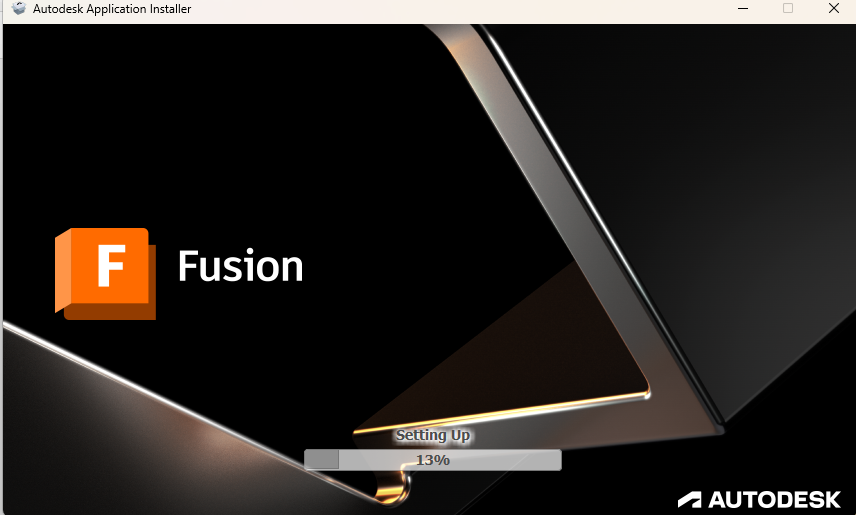
I had used Fusion 360 before, but this time I downloaded it from the official website, downloaded the client file, and then installed it on my system.
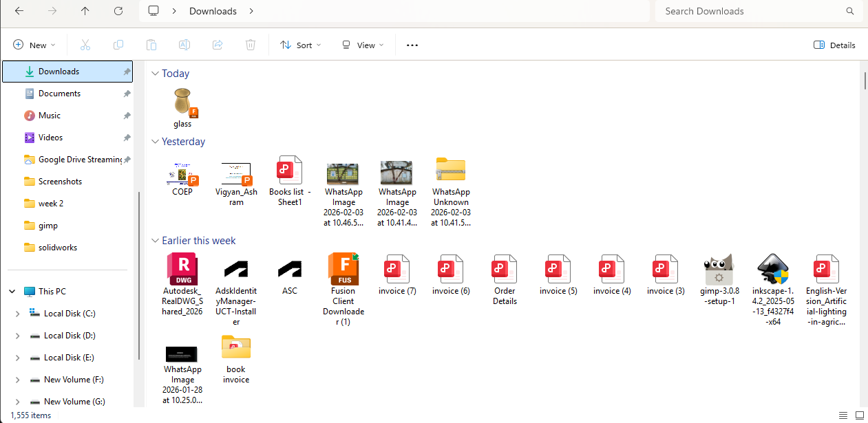
After that, I opened the file and installed it on my system.
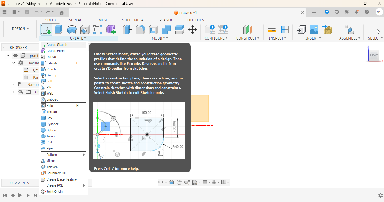
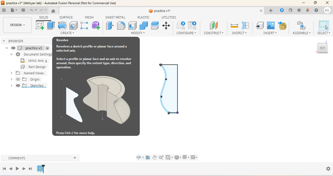
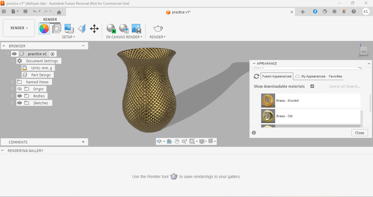
The interface is similar to SolidWorks, with all tools on the top side and the history panel on the left side. I made a small flower pot,
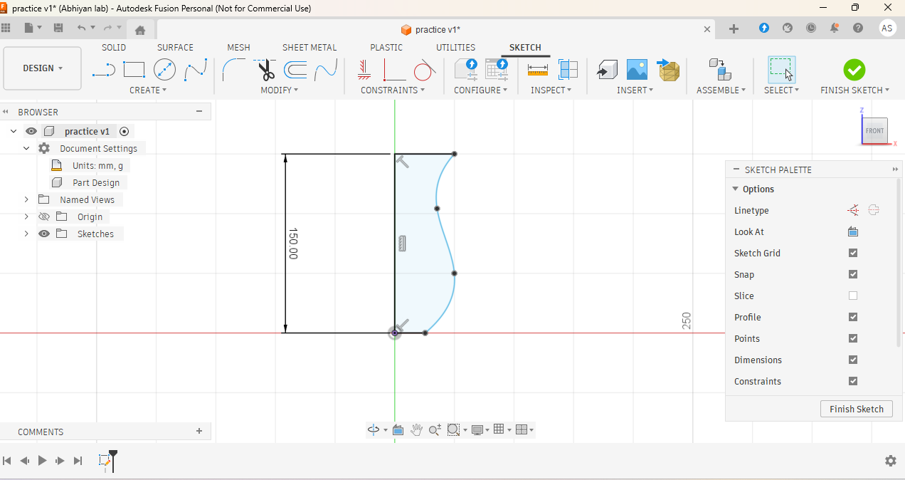
so I selected the vertical plane and used the Line tool to draw a vertical line.
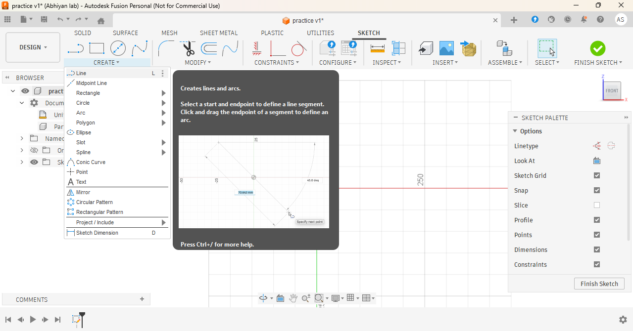
Then I used the Fit Spline tool to draw a curve.
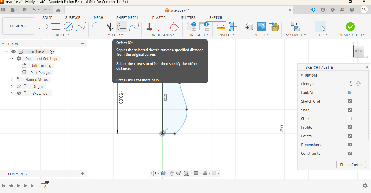
After that, I created an offset tool of the curve and joined it from the top line to the bottom line.
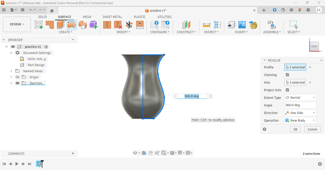
Next, I used the Revolve tool and created a flower pot.
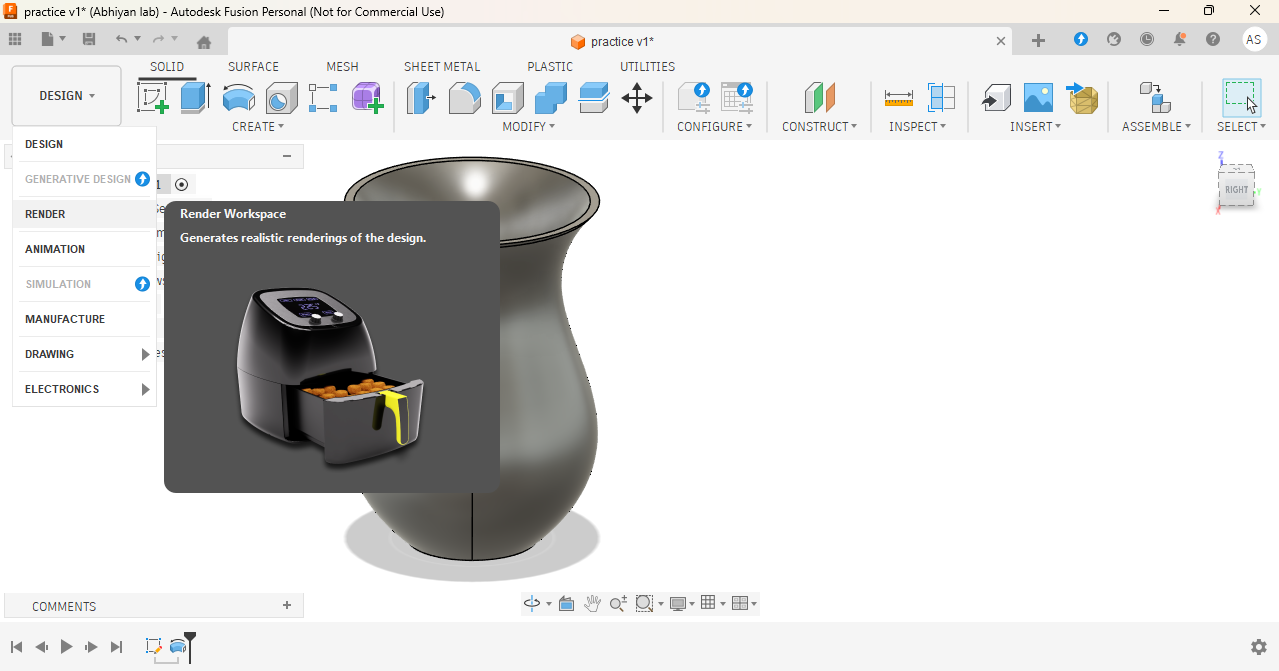
This is the final output.
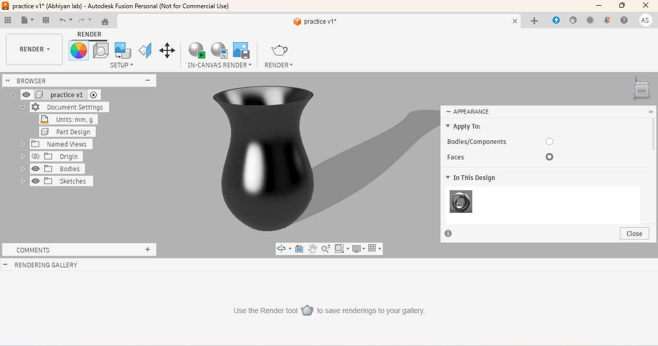
Next, I rendered the model to see the final appearance.
Final output
Xn converts
I use XNConvert software for compressing my images before uploading them to my website. It is an open-source and free software, and anyone can download it directly from the official website:
https://www.xnview.com/en/xnconvert/.
I use this software because when I upload large images directly, my website becomes heavy and takes more time to open.
After compressing the images, the website loads faster and works smoothly. It is very simple and easy to use for everyone.
step 1:- Download the XNConvert software from the official website and install it on your system.
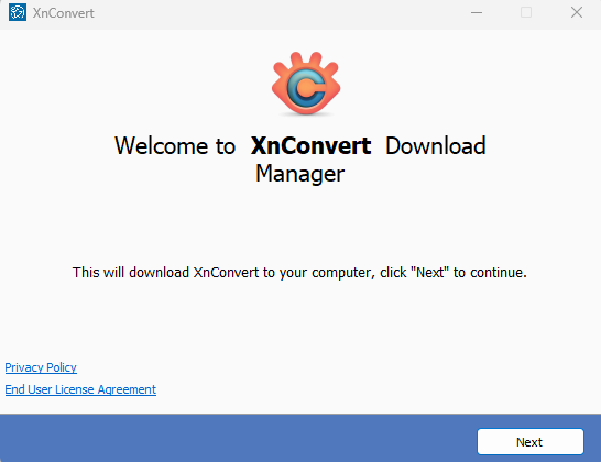
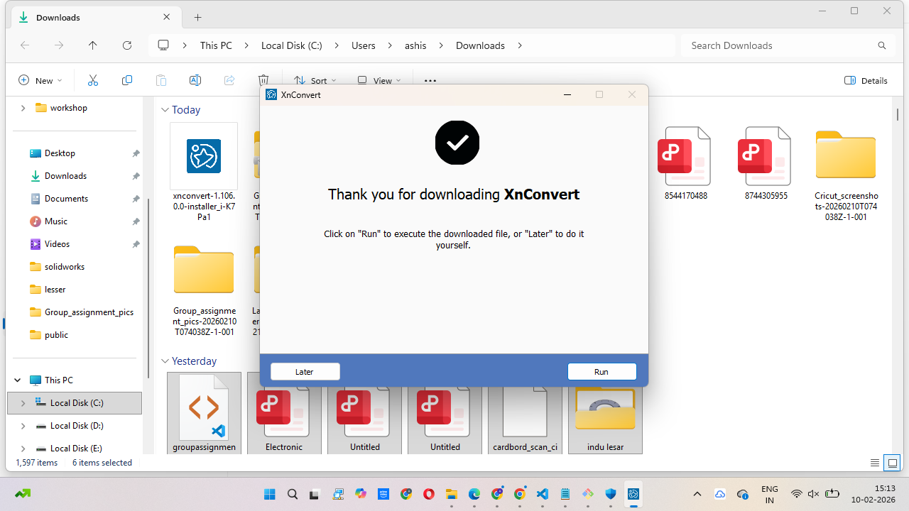
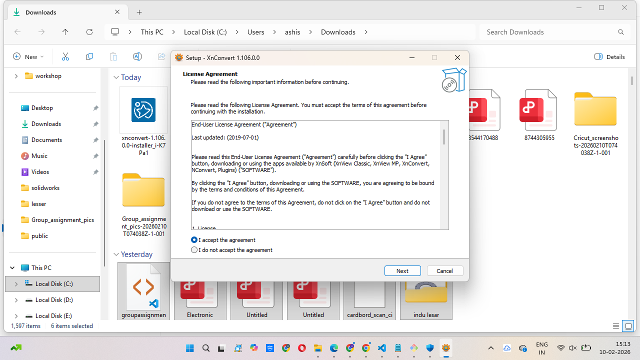
step 2:- Open the setup file and double-click on it. A new installation window will open.
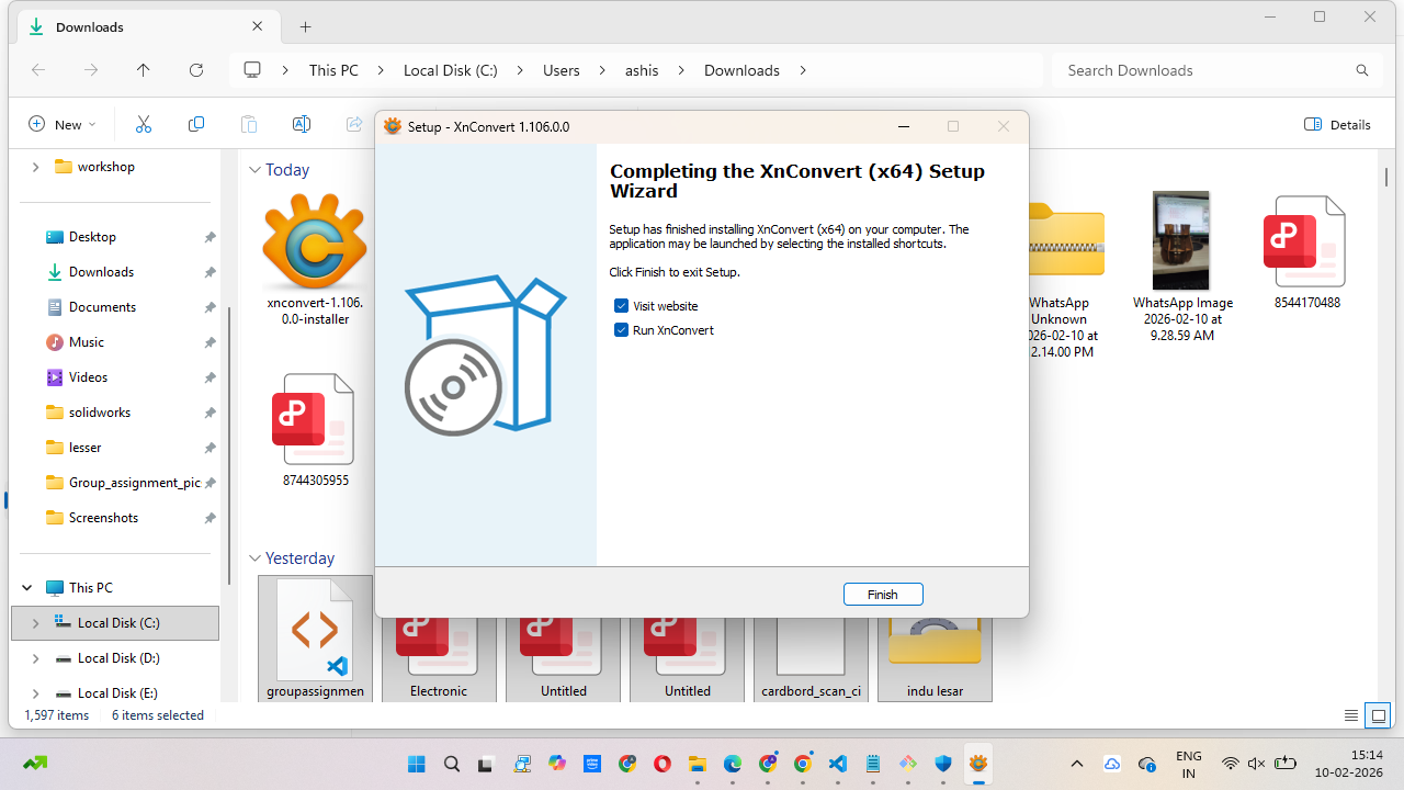
Click on Accept and then click Next to continue the process. Wait a few seconds for the installation to complete, then click Finish.
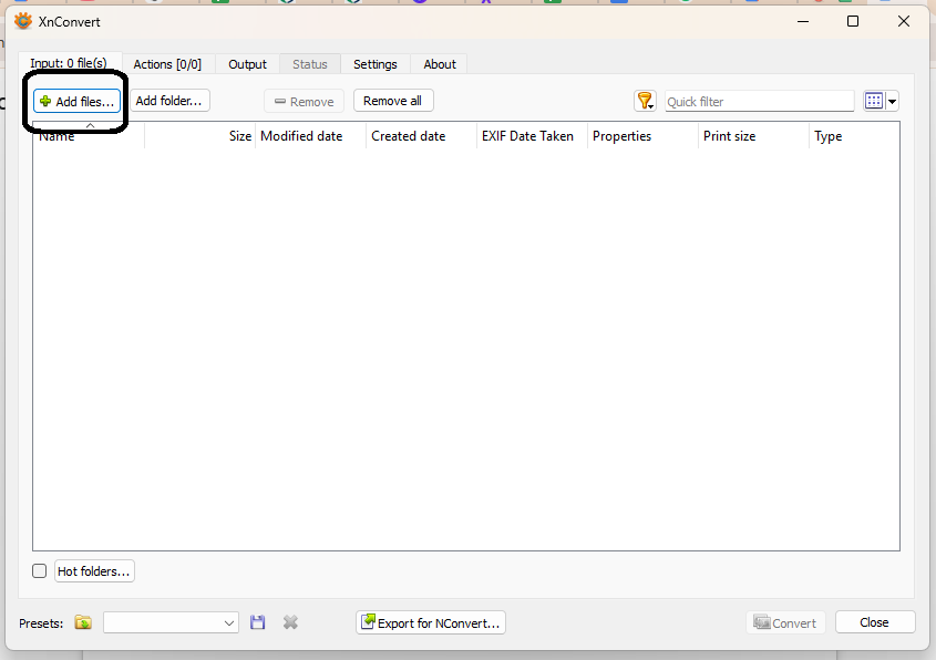
step 3:- After that, open the software window. In this window, you can add images individually, or you can directly add a complete folder of images.
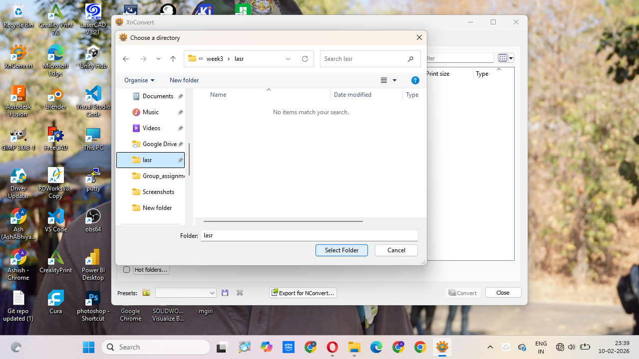
step 4:- In the next step, you can select the folder where you want to save the output files.
You can also choose the file format you need, like JPG or PNG, and adjust some basic settings before converting.
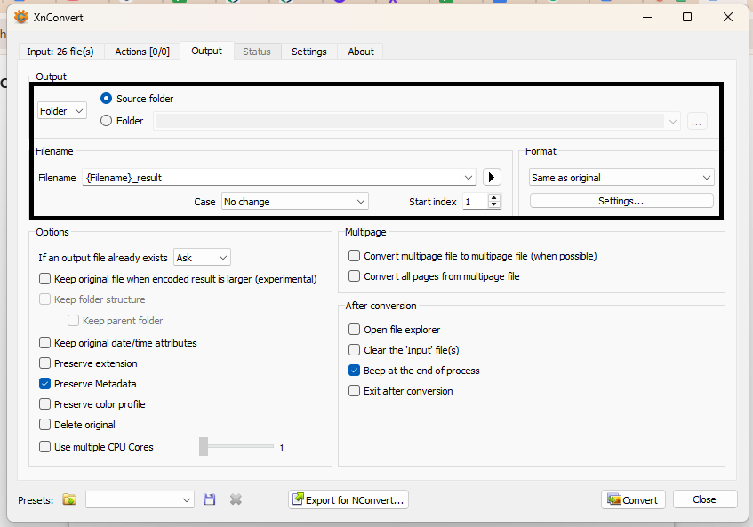
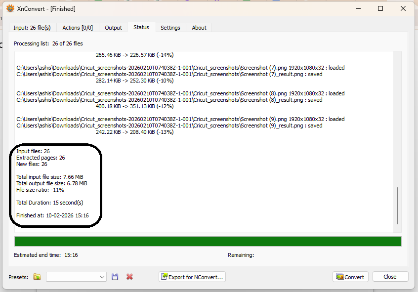
step 5:- After selecting the settings, just click on the Convert button. It will take a few minutes to process the images. After that, it will show the converted files in the selected output folder.
Video Editing
Video editing is important when you record a video for your website or project. Sometimes the video file is very large, and you may want to cut unnecessary parts.
You might also want to add background music, text, or titles to make the video more clear and attractive. Video editing software helps you improve the quality and presentation of your video.
That is why video editing software is very important.
I use Movavi Video Editing Software for editing my videos. It is not open-source software, but it is already installed on my system,
so I use it for general editing purposes. With this software, I make simple edits easily.
Now, I will show the step-by-step process of how I edit my videos using this software.
Step 1:-
For experimental purposes, you can download the Movavi Video Editor software from the official website and install it on your system.
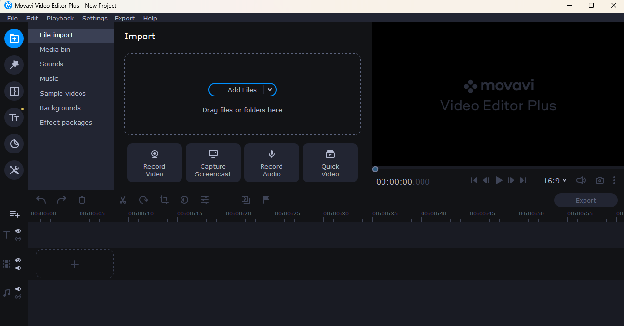
After downloading, run the setup file and complete the installation process. Once the installation is finished, open the software and a simple main window will appear where you can start editing your videos.
You can download the software from the official website:
https://www.movavi.com/videoeditor/.
Step 2:- In the image shown below, you can see that all the boxes are numbered. Each box performs a different task in the video editing software.
Every section has its own function, such as importing files, previewing videos, editing clips, arranging them on the timeline, and exporting the final video.
These numbered boxes help us understand the complete editing process step by step.
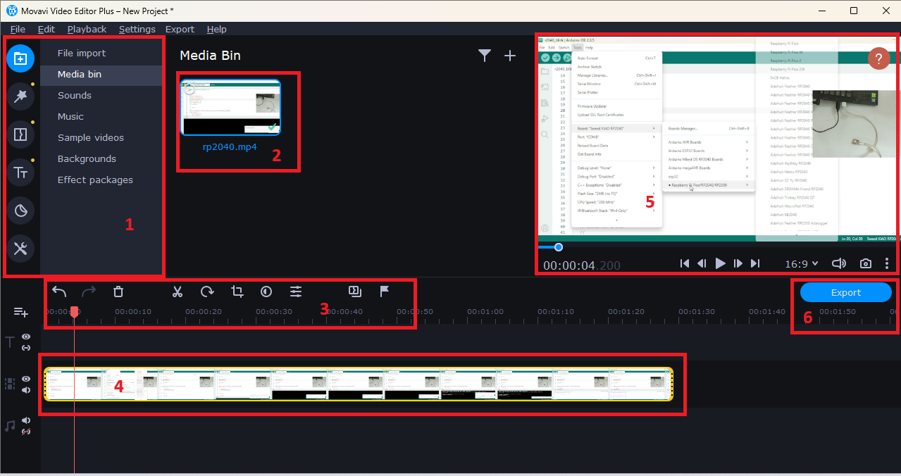
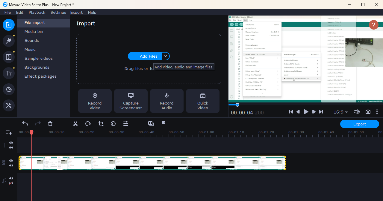
Step 3:- 1.File Import / Media Panel
This section is used to import videos, audio, music, backgrounds, and other media files into the project.
Step 4:- 2.Media Bin
This area shows the imported video file (rp2040.mp4). You can select and drag this file to the timeline.
Step 5:- 3. Editing Tools Bar
This toolbar contains editing options like cut, trim, rotate, crop, and other basic editing controls.
Step 6:- 4. Timeline
This is the main editing area where you arrange and edit your video clips.
Step 7:- 5.Preview Window
This window shows the preview of your video while editing.
Step 8:- 6.Export Button
After completing editing, click this button to export and save your final video.
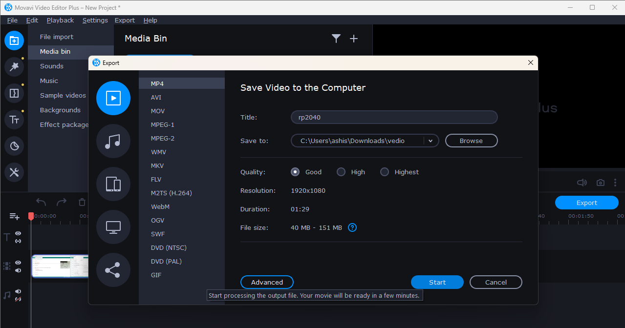
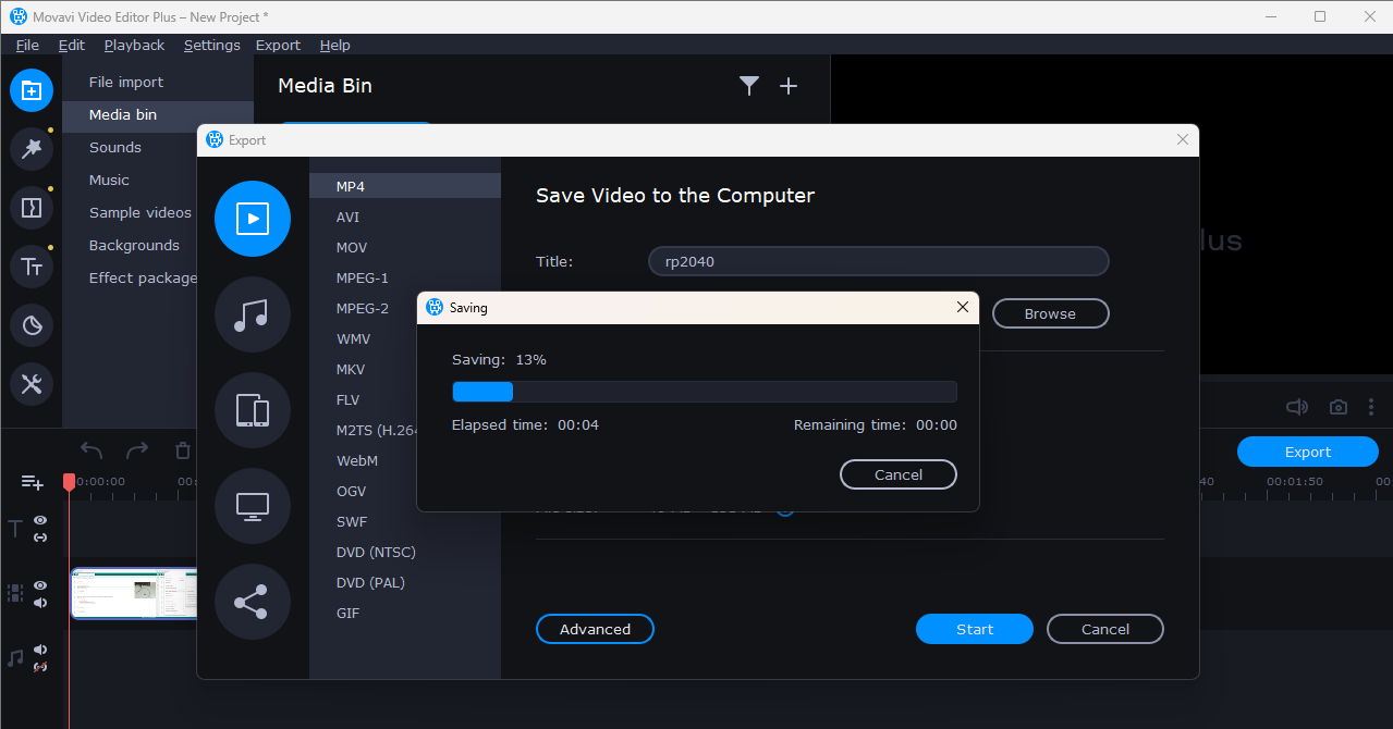
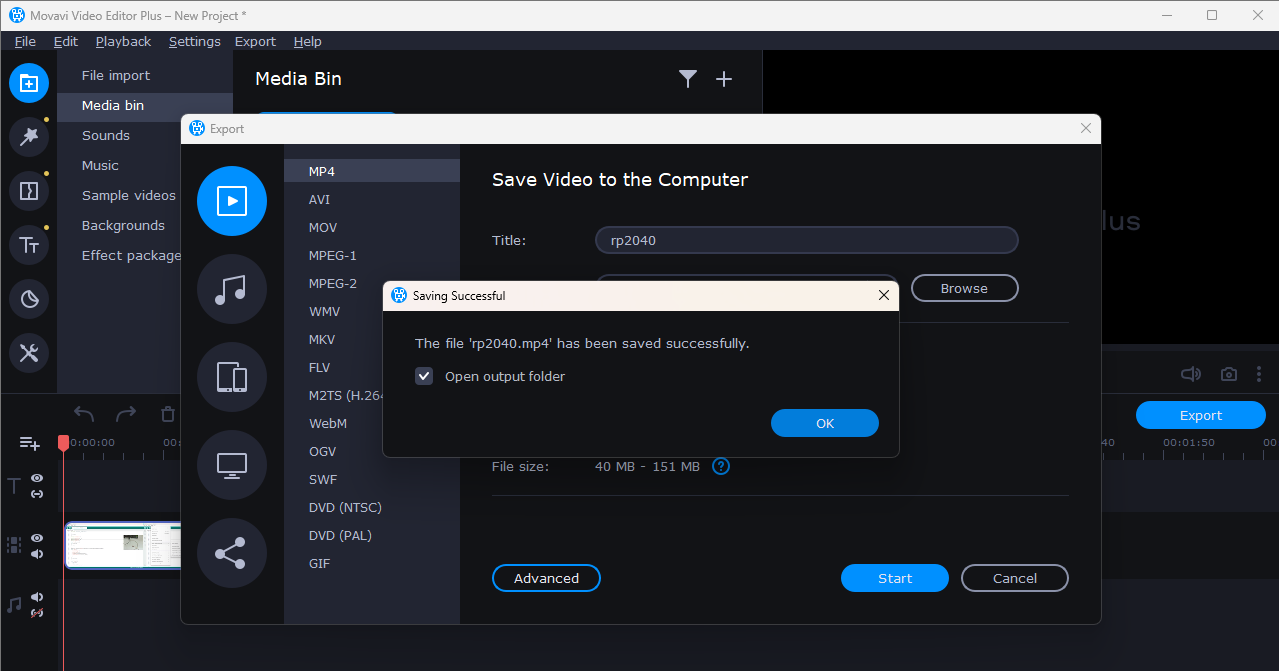
Step 9:- final Video
Your final edited video will be saved in the selected folder.
Vedio compressing
I use HandBrake software for video compressing. HandBrake is an open-source project, so anyone can download it for free from the official website.
I use this software to reduce the video file size before uploading it to my website, so the website loads faster.
To run this software, you need a Microsoft Windows desktop system timming setup file also. After downloading it from the official website, install it on your system and complete the setup process. You can download HandBrake from the official website:
https://handbrake.fr/.
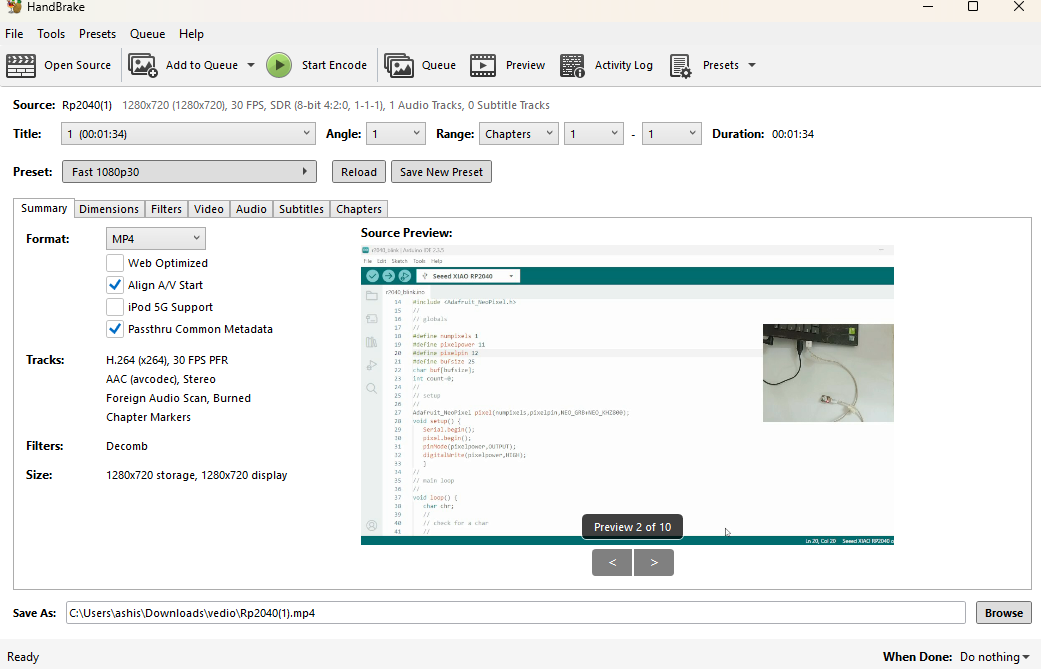
The home screen of HandBrake is very simple and easy to use. You can directly add your video file by clicking on the “Open Source” option.
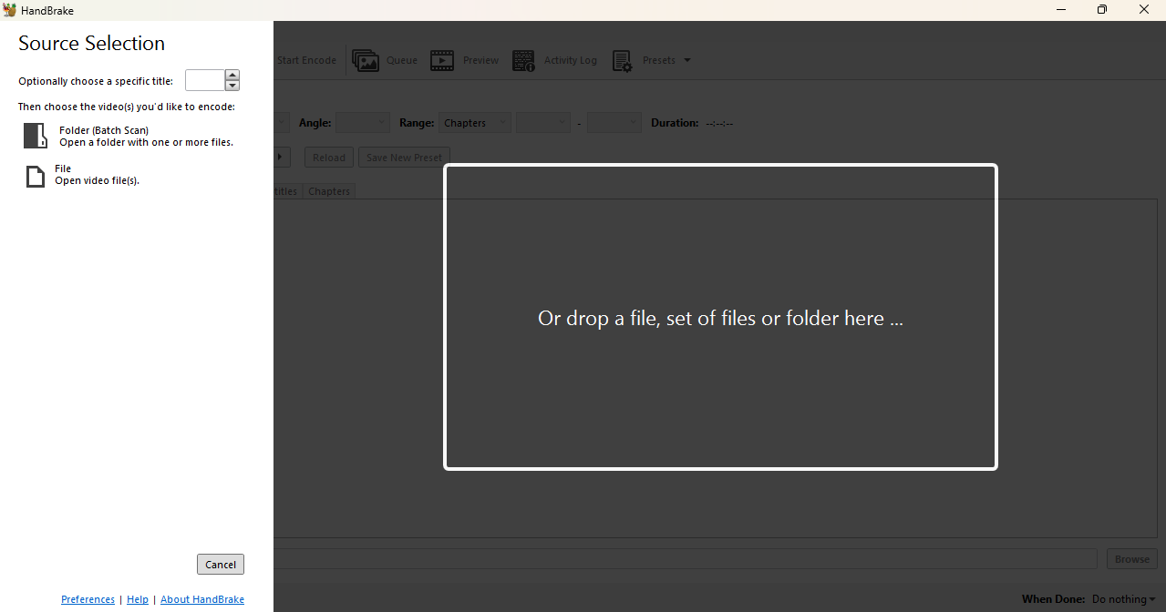
After selecting the file, you can start the compression process easily.
References
1. Inkscape Logo Design Tutorial
2. https://www.69dropsstudio.co.uk/blog/nature-photography-types/
3. https://zeenews.india.com/photos/auto/big-upcoming-car-launches-this-festive-season-tata-mg-kia-2785429
4. https://www.youtube.com/watch?v=0JIR2Zmc3u8
5. https://www.gimp.org/downloads/
6. https://www.xnview.com/en/xnconvert/
7. https://www.movavi.com/videoeditor/
8. https://handbrake.fr/
9. https://www.youtube.com/watch?v=Ww-Krcff_48&list=PLHEouj-sdEJE6dkRSZjs41efoCf99yIaU