Group Assignment
Computer controlled cutting
Group assignment
This week, we worked on a group assignment related to laser cutting and scanning. We performed different trials on the laser cutting machine. The main aim of the assignment was to understand the laser cutting machine, learn how to operate it safely, and find the best speed and power settings. We also calculated the kerf value for different materials so that these values can be used later in our individual assignments and projects. Knowing the correct speed, power, and kerf helps us modify our CAD designs parametrically. I was part of the team working with plywood, MDF and acrylic materials. We shared the work among ourselves, where I handled the engraving process from designing to machine operation and documentation.
Cardboard cutting and scanning
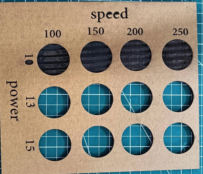
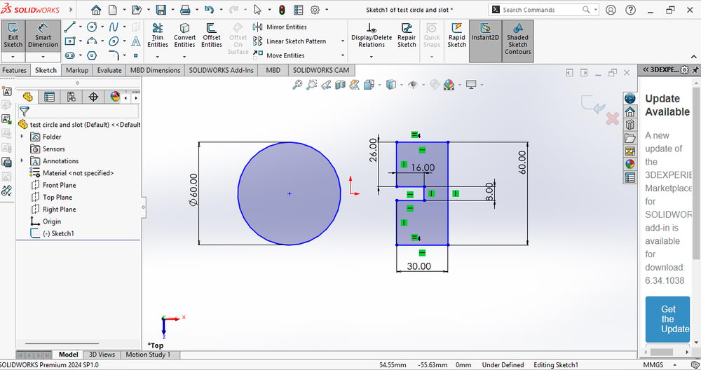
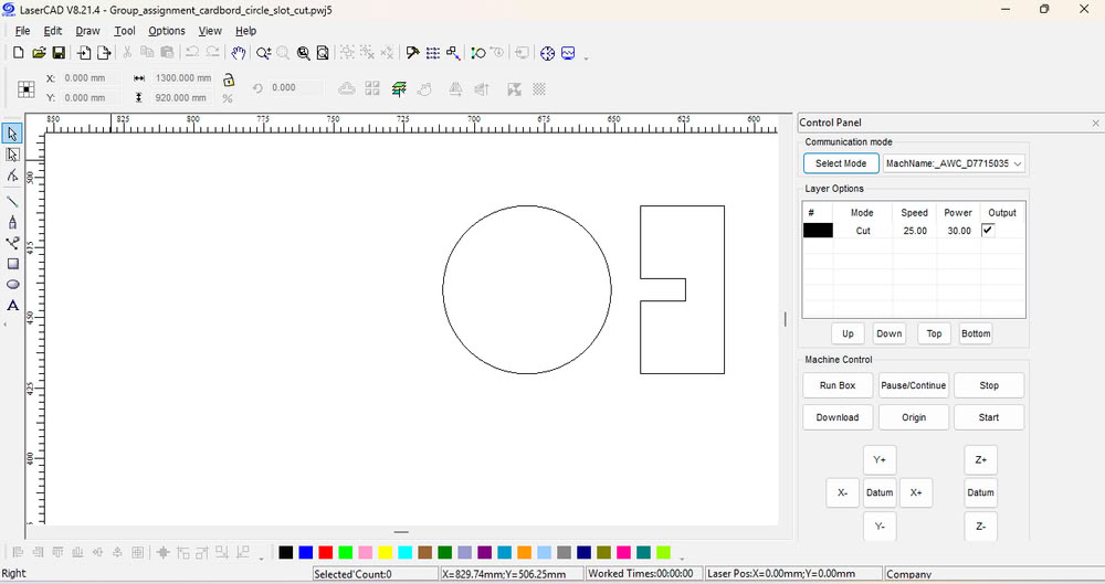
In this group assignment, we cut 3 mm and 4 mm cardboard sheets to test cutting, engraving, and slot fitting. For cutting and engraving, I first created the design in SolidWorks. After completing the design, I exported the file in a suitable format for laser cutting. Then, I opened the design in LaserCAD software, which is used to control the laser cutting machine. In LaserCAD, I set different layers for cutting and engraving and adjusted the speed and power settings according to the material thickness. After checking all settings, the file was sent to the laser machine for cutting and engraving.
 |
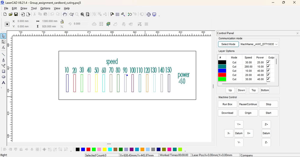 |
This file was used to cut 4 mm thick cardboard using different power and speed settings. Multiple test cuts were performed to observe how changes in laser power and cutting speed affect the cutting quality, depth, and edge finish. From the results, it was possible to identify the optimal power and speed combination required for clean cutting on 4 mm material.
 |
 |
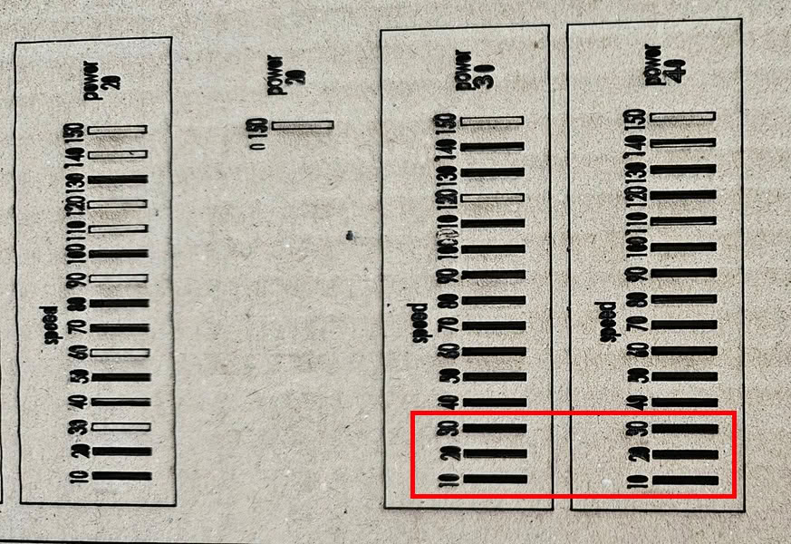
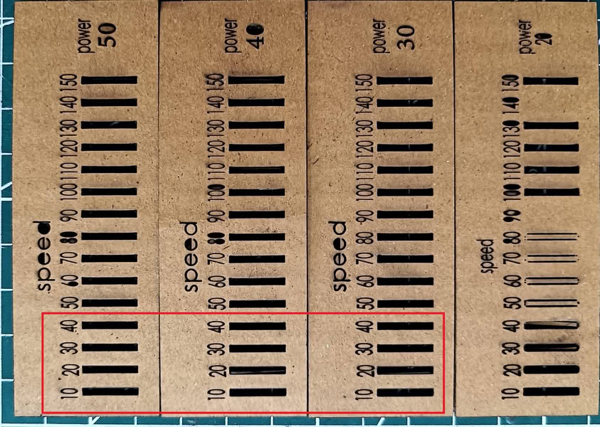
Conclusion: For 4 mm cardboard, the best cutting results were achieved when the machine was operated at a speed between 10–30 and power between 30–40. These settings provided clean cuts and proper material separation on our laser cutting machine.The same design file was also used to cut 3 mm cardboard. Different power and speed settings were tested on the 3 mm material. The cutting quality results were observed and compared. This helped us understand the correct settings for thinner material.
 |
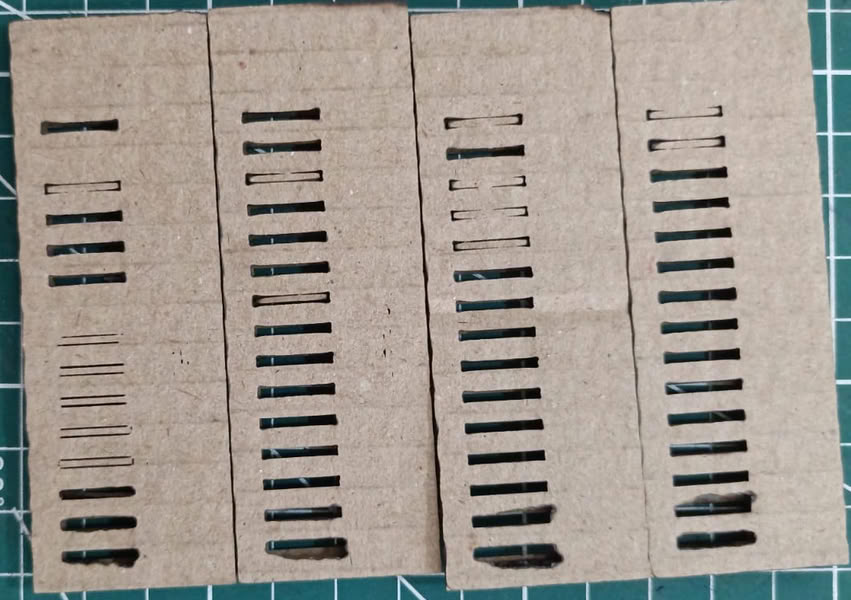 |
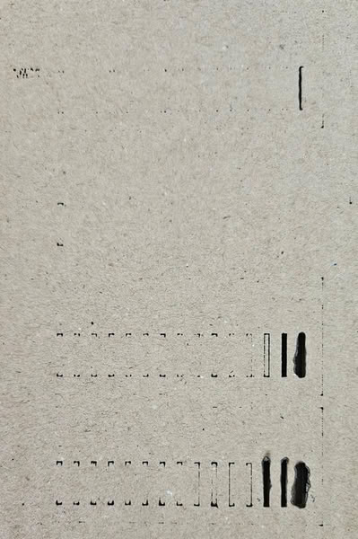
Conclusion: For 3 mm cardboard, the best cutting results were obtained at a speed range of 10–50 and power range of 20–50. These settings gave clean and accurate cuts on the material.After that, we performed engraving on 4 mm and 3 mm cardboard using suitable laser settings. The engraving quality was observed by changing the power and speed values.
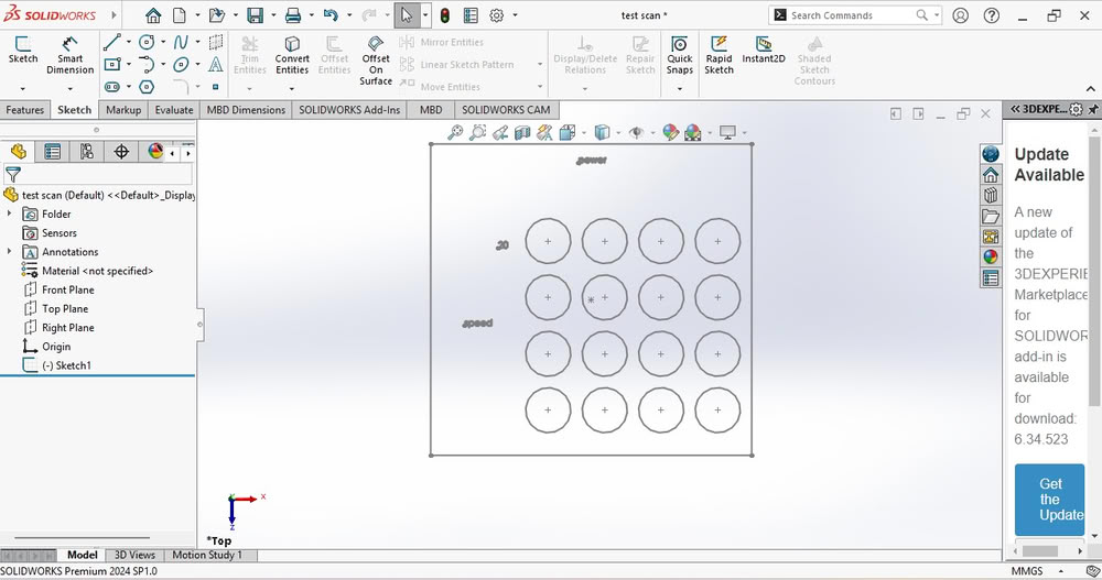 |
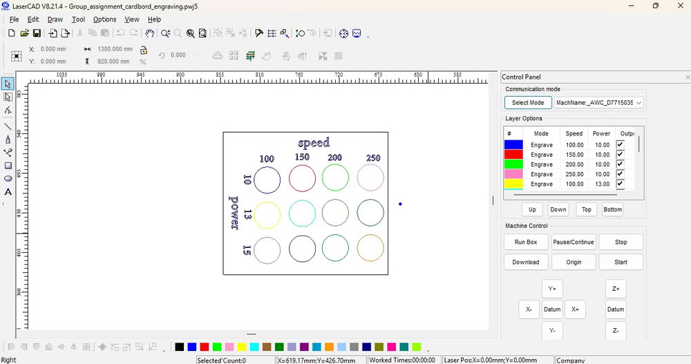
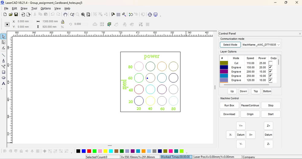
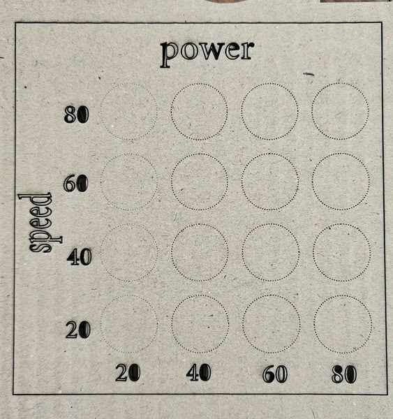
The design file was imported into LaserCAD, and different speed and power settings were set for each circle.
 |
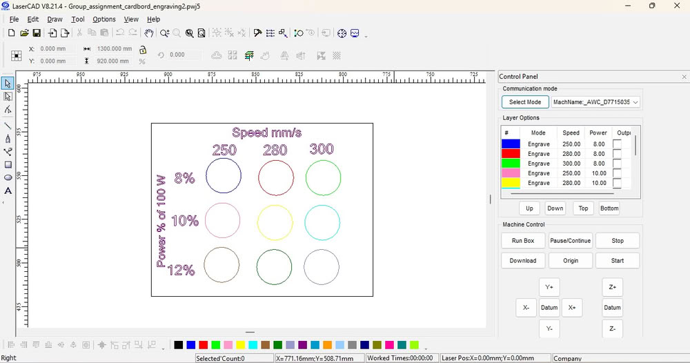 |
After that, the results are shown in the images.
 |
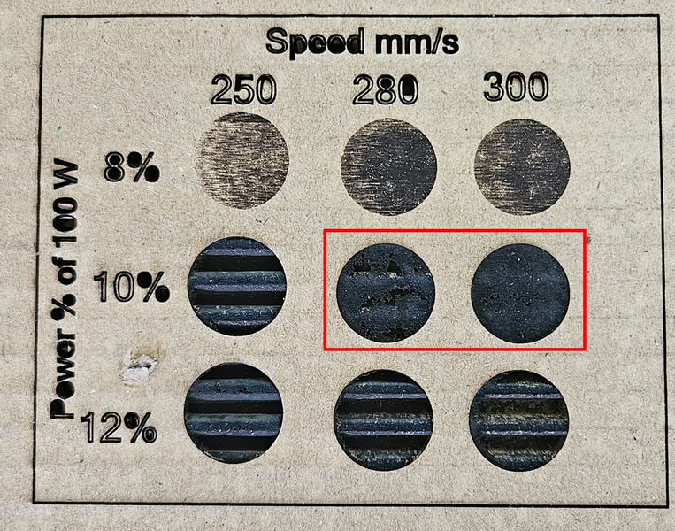 |
Conclusion: Good quality engraving on 4 mm cardboard was achieved at a speed of 280–300 and power of 10%. These settings produced clear and clean engraving results.We used the same design for hole cutting to keep the size and alignment accurate.
 |
 |
Kerf calculation of cardboard
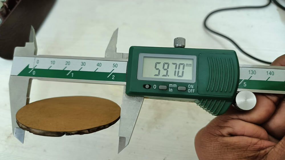
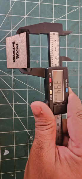
We calculated the kerf value for the 3 mm sheet because we are using 3 mm material for our construction kit. Knowing the kerf value helps us adjust the slot size so that the parts fit properly after laser cutting.
 |
 |
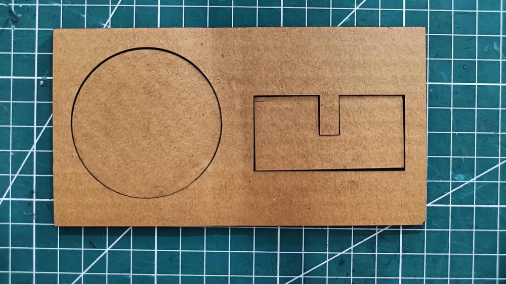 |
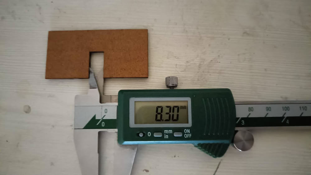
we checked and measured the actual dimensions of the cut piece. |
The designed circle diameter was 60 mm, but after laser cutting, the measured diameter was 59.70 mm. Similarly, the designed slot width was 8 mm, and the measured dimension after cutting was 8.32 mm. This dimensional variation is due to the laser kerf effect. Kerf formula= design dimension—after cut dimension /2kerf= 8mm - 8.30mm/2kerf=0.15mmThe kerf value for 3 mm cardboard is 0.15 mm.
 |
 |
MDF and Plywood Scanning
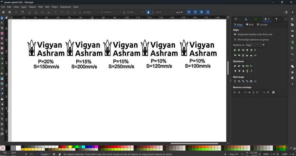
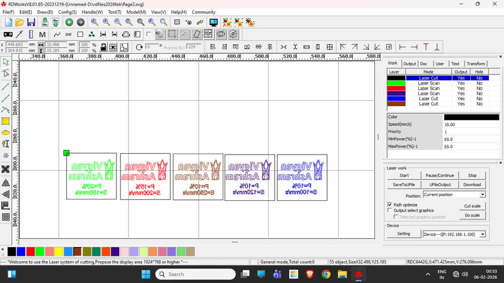
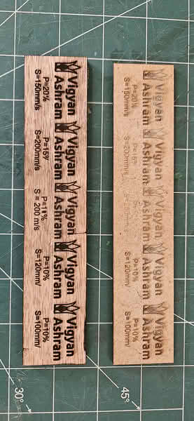
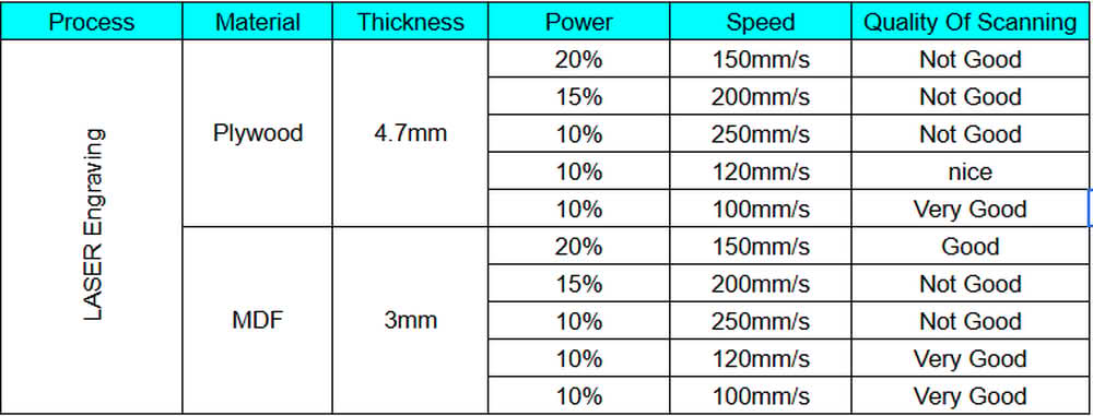
We used 3 mm thick plywood and MDF sheets for the scanning and engraving process. To understand how the laser machine works with different speed and power settings, I created one SVG file in Inkscape for both plywood and MDF. This file was then imported into RDWorks, where different speed and power values were applied. The snapshots show the SVG file, the layout in RDWorks, and the engraved results on plywood and MDF sheets. By observing the engraving quality, we concluded that for 4 mm plywood and MDF sheets, the machine gives very good engraving results at a speed of 100–120 mm/s with 10% power.
 |
 |
 |
 |
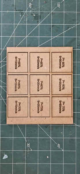
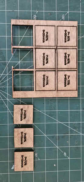
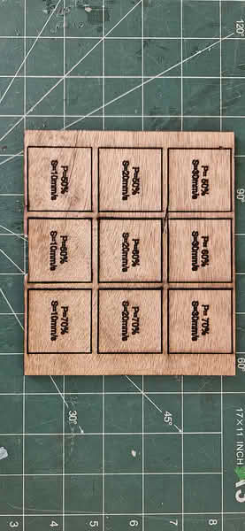
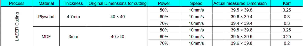
Plywood and MDF Cutting
For cutting MDF and plywood, we used 3 mm thick MDF and plywood sheets. I created the cutting design in Inkscape and then imported it into RDWorks software. After importing the file, we assigned different colors to the cutting paths in RDWorks, where each color represented a different speed and power setting for the laser cutting process.
 |
 |
Below are the pictures of the plywood and MDF sheets that we used for cutting operation.
 |
 |
 |
 |
Conclusion
For MDF(3mm) cutting, we observed that with power settings of 50%, 60%, and 70% at a speed of 10 mm/s, the material was cut properly. At a speed of 20 mm/s, the MDF was cut at higher power levels, but at 20 mm/s with only 50% power, it did not cut. Similarly, at a speed of 30 mm/s with power settings of 50%, 60%, and 70%, the material was not cut properly.
For plywood(4.7mm) cutting, we observed that when the speed was set to 10 mm/s and the power was 50%, 60%, or 70%, the plywood was cut successfully. However, for other trials with a higher speed of 20 mm/s and power levels of 50%, 60%, and 70%, the plywood did not get cut properly.
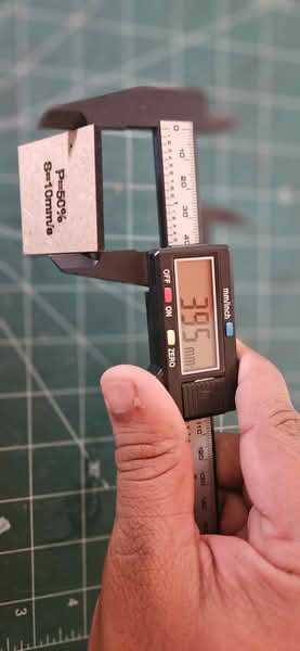
Kerf calculation for MDF and Plywood
 |
 |
| MDF Material | Plywood Material |
Acrylic scanning and cutting
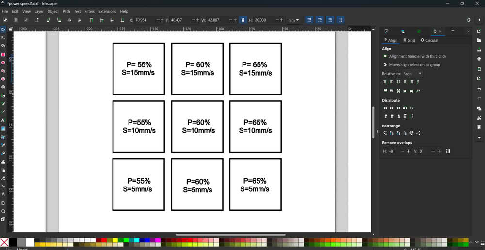
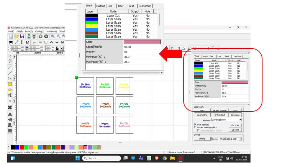
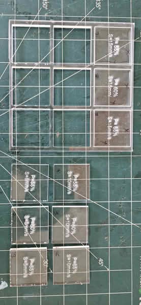
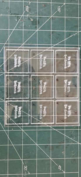
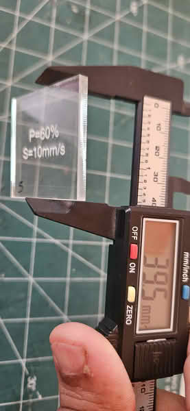
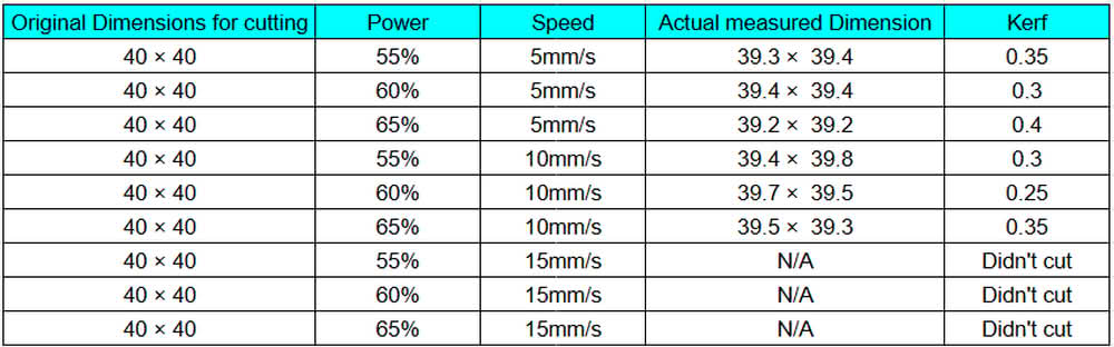
We chose an acrylic sheet that was 4.4 mm thick for our testing. To understand how the laser machine performs with different speed and power settings on acrylic, our team first created a simple design in Inkscape. After completing the design, we saved it as a SVG file so it could be used in the laser software. We then imported this SVG file into RDWorks. Inside RDWorks, we changed the colors of the cutting lines. Each color was set with different speed and power values. This helped us test multiple settings in one single design and compare the cutting results easily.
 |
 |
 |
 |
Conclusion:
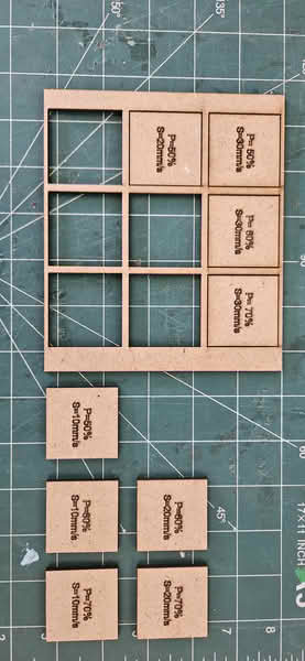
During testing, we observed that the acrylic blocks were successfully cut when the speed was set to 5 mm/s or 10 mm/s with power levels of 55%, 60%, and 65%. The cuts were clean and went through the full thickness of the material. However, when we increased the speed to 15 mm/s, even after using the same power settings, the acrylic did not cut completely. This shows that higher speed reduced the cutting effectiveness because the laser did not get enough time to fully penetrate the 4.4 mm thick acrylic sheet.
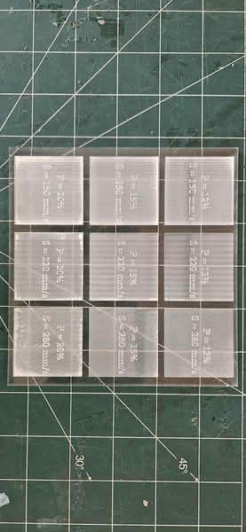 |
| During the engraving (scanning) test, two acrylic blocks were engraved properly. The best results were achieved when the speed was set to 280 mm/s with power levels of 12% and 15%. The engraving was clear and visible on the surface without cutting through the material. These settings worked well for surface marking on the 4.4 mm acrylic sheet. |