Group Work 2026 - Learn and Test Our Desktop CNC
Assignment: Characterize the design rules for our in-house PCB production process / Submit a PCB design to a board house.
Milling Machine
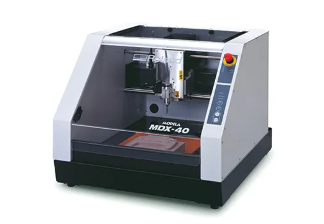
In 2026, we continued to use the Roland MDX-40 for desktop CNC machining and PCB-related fabrication tasks. The Roland MDX-40 3D Milling Machine is a versatile desktop milling machine suitable for prototyping, model making, educational use, and small-scale subtractive manufacturing.
The machine provides a relatively large working area for a desktop CNC system, adjustable spindle speed, and compatibility with Roland machining software. These features make it suitable for both general machining and experimental PCB production.
Safety First
When operating the Roland MDX-40, the following safety precautions should be followed:
- Wear safety glasses to protect the eyes from chips, dust, and broken tool fragments.
- Use a dust mask when necessary, especially when PCB milling generates fine particles.
- Secure the workpiece before machining.
- Keep hands away from the cutting area while the spindle is rotating.
- Maintain cutting tools and replace damaged or blunt tools.
- Ensure proper grounding of the machine and connected equipment.
- Follow the manufacturer's operating instructions.
- Stop the spindle completely before adjustment, cleaning, or tool replacement.
Equipment Usage
Roland MDX-40 Machine Notes
- Maximum machining range: 305 mm [X] × 305 mm [Y] × 105 mm [Z]
- Spindle speed range: 4500 to 15000 RPM
- Keep the table surface clean and free from debris before each job.
- Secure the material firmly before machining.
- Select suitable cutting speed, depth, and feed rate according to the material and tool.
- For fine PCB tools, reduce the cutting load to minimize tool breakage.
- After machining, inspect the tool, remove debris, and power down safely.
Clamping the Workpiece
Before machining, clean the platform and make sure the workpiece is flat. We used double-sided tape to secure the material firmly to the machining platform.
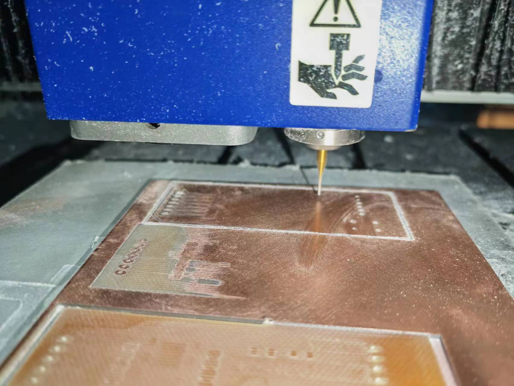
Correct clamping is especially important for PCB milling because even a small height difference can affect milling depth and trace quality.
Setting the Origin
Use the direction keys to move the tool above the workpiece. Adjust the X, Y, and Z axes to the required machining origin, then press ENTER to complete the origin setting.
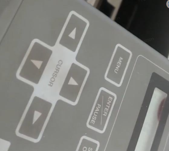
For PCB milling, the Z-axis origin is particularly important because the copper layer is very thin. An incorrect Z origin can cause incomplete isolation cuts or excessive cutting depth.
Software for Roland
The software used with our Roland MDX-40 is MODELA Player 4.
Machining Workflow
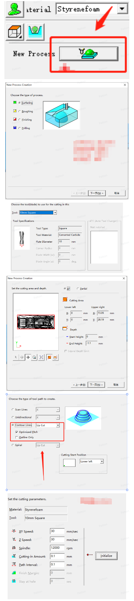
First, import the 3D model into MODELA Player 4.

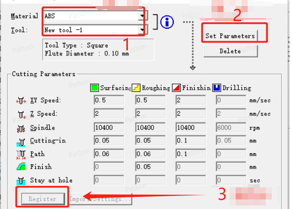
After importing the model, confirm the model orientation, machining direction, margin, and machining area. Then add the correct cutting tool and specify its diameter.
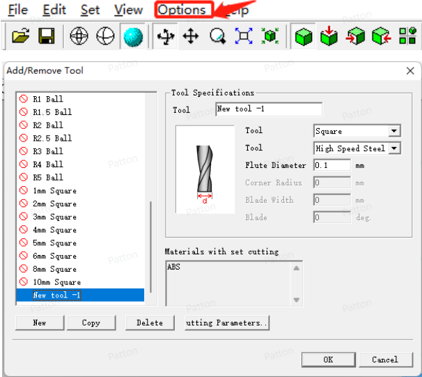
Configure the machining parameters for the selected tool, including the cutting conditions appropriate for the workpiece and machining stage.
Finally, set the machining process, such as roughing or finishing, before generating and running the toolpath.
Problems and Improvements Found During Testing
Problems
During machine testing, we observed several common problems:
- Tools with a diameter below 0.5 mm are more likely to break during PCB machining.
- Some parts cannot be completely cut through after machining.
- The machined surface can be rough.
- Incorrect origin settings can cause asymmetric machining.
- Uneven workpiece clamping can cause inconsistent milling depth.
Optimization Solutions
- Reduce the cutting load when using small-diameter tools.
- Use conservative cutting parameters for PCB milling.
- If the surface is rough, increase spindle speed appropriately and reduce the material removed per pass during finishing.
- Make sure the workpiece is flat before setting the Z origin.
- Check the machining area and toolpath before starting the final machining operation.
Group Work 2026 - Submit a PCB Design to a Board House
For the board-house part of the assignment, we continued to develop a custom expansion board based on the Seeed Studio XIAO ESP32-C3 using LCEDA / EasyEDA.
The board is designed to connect with A4988 stepper motor driver modules, allowing one XIAO ESP32-C3 to control four stepper motors independently. The workflow includes component selection, schematic design, PCB layout, trace routing, ground-plane design, design-rule checking, and manufacturing-file generation.
PCB Design Process
The PCB design was created using LCEDA / EasyEDA, which can be accessed online through EasyEDA.
Project Initialization
Create a new electronic design project in EasyEDA and select Project.
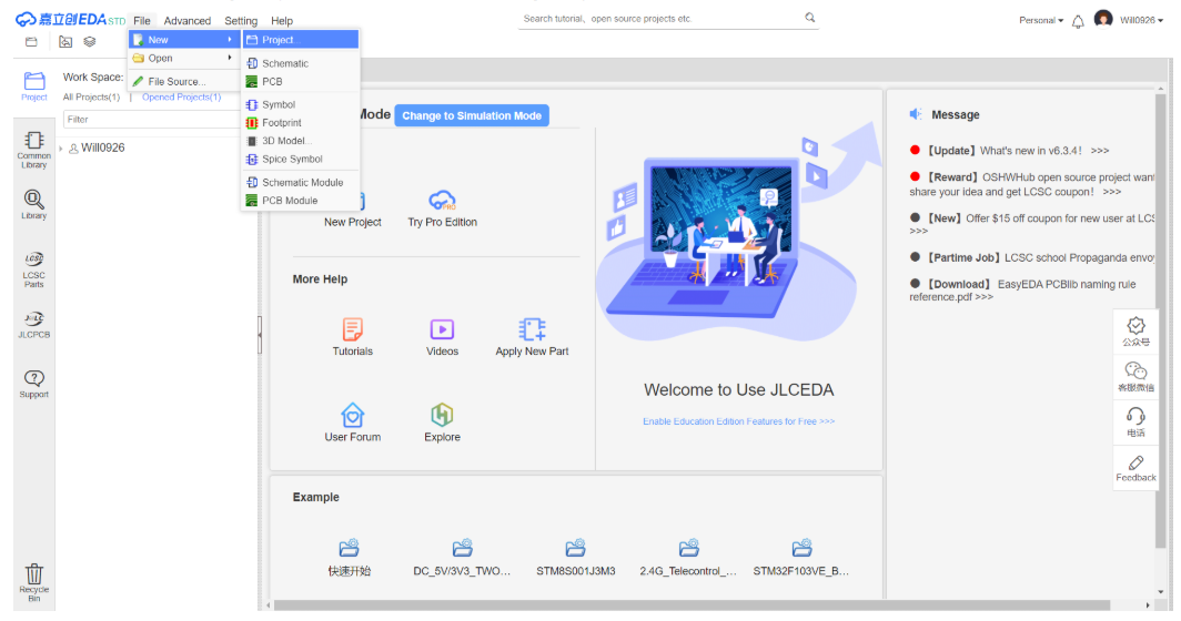
After creating the project, save it and enter the schematic workspace.
Component Library Preparation
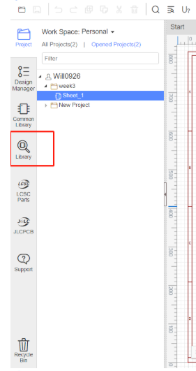
Open the component Library and search for "XIAO ESP32C3 PCB". Select the required component model and place it in the schematic. The A4988 and other required components are added using the same method.
Hardware Specification Analysis
Pin Definitions
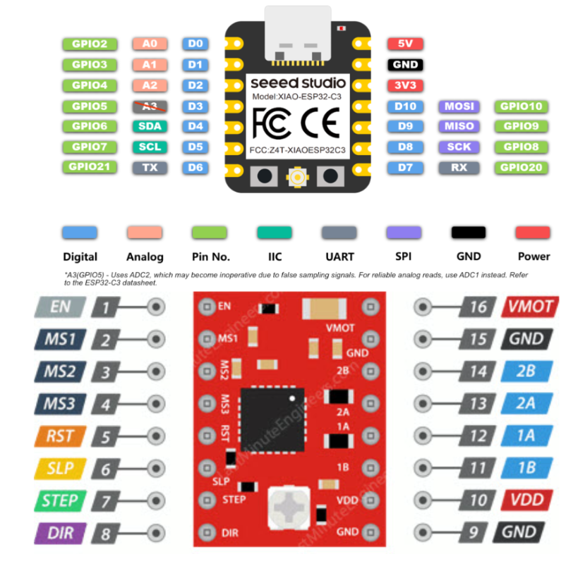
The figure below shows the pin definitions used for the XIAO ESP32-C3 and A4988. Based on these definitions, four A4988 modules can be connected so that four stepper motors can be controlled independently.
A4988 Technical Specifications
| Parameter Type | Specification |
|---|---|
| Motor Output Voltage | 8 V – 35 V |
| Logic Input Voltage | 3 V – 5.5 V |
| Continuous Current per Phase | 1 A |
| Maximum Current per Phase | 2 A |
| Microstepping Resolution | Full, 1/2, 1/4, 1/8, 1/16 |
Power System
The A4988 requires two power connections:
- Logic Power: VDD-GND, 3 V–5.5 V
- Motor Power: VMOT-GND, 8 V–35 V
The motor-power input should use suitable decoupling capacitors to stabilize the supply during rapid motor-current changes.
Microstepping Control
The A4988 supports microstepping through MS1 / MS2 / MS3.
A NEMA 17 motor with a 1.8° step angle has 200 full steps per revolution. In quarter-step mode:
200 × 4 = 800 microsteps per revolution
Motion Control
- STEP: Each valid pulse advances the motor by one selected step or microstep.
- DIR: Controls the motor rotation direction.
- EN: Enable control, normally active-low.
- SLP: Sleep control.
- RST: Reset control.
- 1A / 1B / 2A / 2B: Motor phase outputs.
Pin Assignment Plan
| XIAO Pin | Function |
|---|---|
| D0 | Motor 1 STEP |
| D1 | Motor 1 DIR |
| D2 | Motor 2 STEP |
| D3 | Motor 2 DIR |
| D4 | Motor 3 STEP |
| D5 | Motor 3 DIR |
| D6 | Motor 4 STEP |
| D7 | Motor 4 DIR |
| GND | All A4988 ENABLE |
| GND | All A4988 GND |
| 5V | All A4988 VDD |
This assignment allows independent STEP and DIR control for four motor-driver channels.
Circuit Design Implementation
Schematic Design
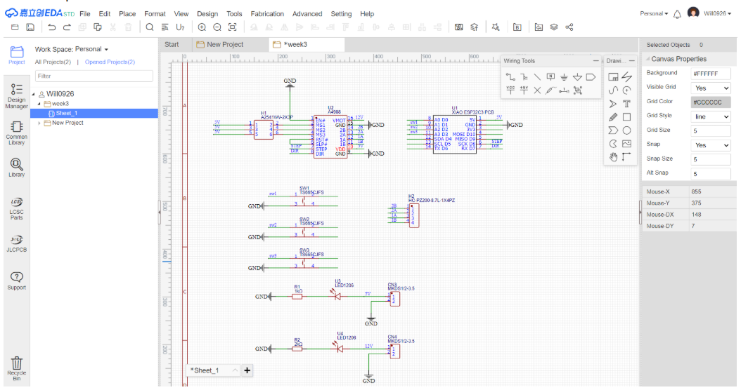
After placing the required components, connect the XIAO ESP32-C3, A4988 drivers, power rails, switches, resistors, and other circuit nodes. Check for incorrect connections, short circuits, and missing connections before proceeding to PCB layout.
PCB Design
After completing the schematic, transfer the design to the PCB layout environment.
Component Placement
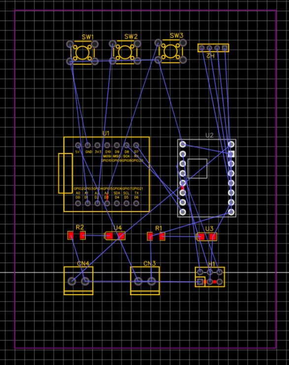
Place the XIAO ESP32-C3, A4988 interfaces, switches, resistors, connectors, and other components on the PCB. The placement should consider signal routing, power routing, assembly access, and mechanical interference.
Routing Traces
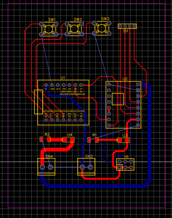
For our board, we used the following trace widths:
- 5 V line width: 0.8 mm
- 12 V line width: 1.6 mm
- Other signal line width: 0.3 mm
The wider power traces are used for higher-current paths, while smaller signal traces can use narrower routing.
Ground Connection
Use the Copper Area function to connect the GND network and create a ground plane.
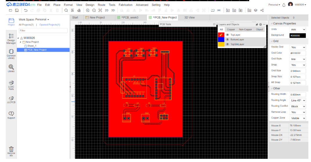
The ground plane simplifies ground routing and provides a more consistent return path for the circuit.
PCB Design Review
Before manufacturing, perform a Design Rule Check (DRC) and verify:
- Trace-to-trace clearance
- Trace-to-pad clearance
- Minimum trace width
- Hole and via size
- Board-edge clearance
- Component spacing
- Unrouted nets
- Power and ground connectivity
This step helps identify PCB layout problems before fabrication.
Generating Manufacturing Files
Export Gerber Files
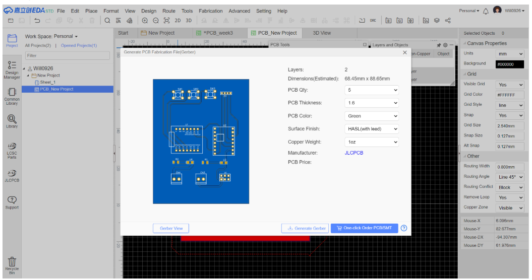
Use the LCEDA export function to generate the Gerber files required by the PCB manufacturer.
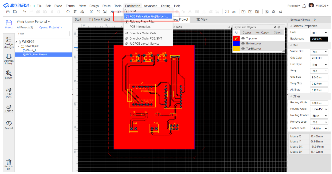
Before submission, check that the manufacturing package contains the required board outline, copper layers, solder mask, silkscreen, and drill information.
Bill of Materials (BOM)
Update the BOM with the component values, part numbers, package types, and quantities used in the final design.
A correct BOM is important for component procurement and PCB assembly.
2026 Group Findings
This group exercise allowed us to compare in-house desktop CNC fabrication with professional PCB board-house production.
For the Roland MDX-40, the most important factors are accurate clamping, correct origin setting, suitable spindle and cutting parameters, and conservative settings for small tools.
For the PCB board-house workflow, the most important factors are correct schematic connectivity, suitable footprints, trace-width selection, ground-plane design, DRC checking, and correct Gerber and BOM generation.
In-house milling is useful for rapid prototyping and immediate testing, while board-house manufacturing provides better repeatability, finer production capability, solder mask, silkscreen, plated holes, and a more production-ready PCB.