

THE BRIEF
Group assignment
- Complete the lab’s safety training.
- Test runout, alignment, fixturing, speeds, feeds, materials and toolpaths for the machine.
- Document the shared work on the group page and reflect on the learning on each individual page.
Related individual assignment
Make something big (approximately metre-scale): design it, mill it and assemble it.
Extra credit: avoid fasteners or glue, include curved surfaces, or use three-axis toolpaths.
01 / SAFETY & MACHINE
Start with a safe setup
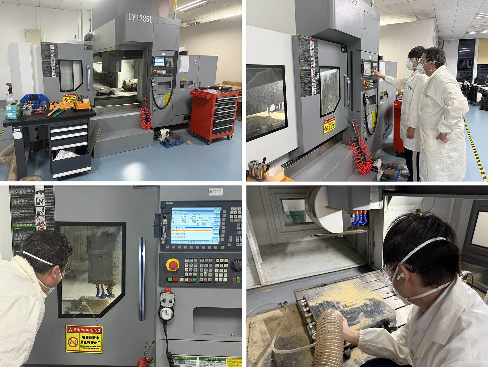
Our group completed the mandatory safety training for the LY1285L machining centre with a Siemens SINUMERIK 828D controller at the University of Nottingham Ningbo China.
Safety points covered in training
- Personal protective equipment: safety glasses or goggles, laboratory coats and particle dust masks during preparation and operation. Long hair was tied back, and loose clothing and jewellery removed.
- Enclosure and emergency stop: the enclosure was kept closed and interlocked while the spindle was running. Emergency stops and door-interlock warnings were checked before machining.
- Chip and dust management: wood chips were vacuumed away only after the spindle had completely stopped and the cycle was paused or finished.
02 / CAM PREPARATION
From the model to a machining program
We used Siemens NX to define the stock and coordinate systems, assign cutting operations, simulate toolpaths and post-process programs for the SINUMERIK 828D.
Select a screenshot to inspect its full-resolution details.
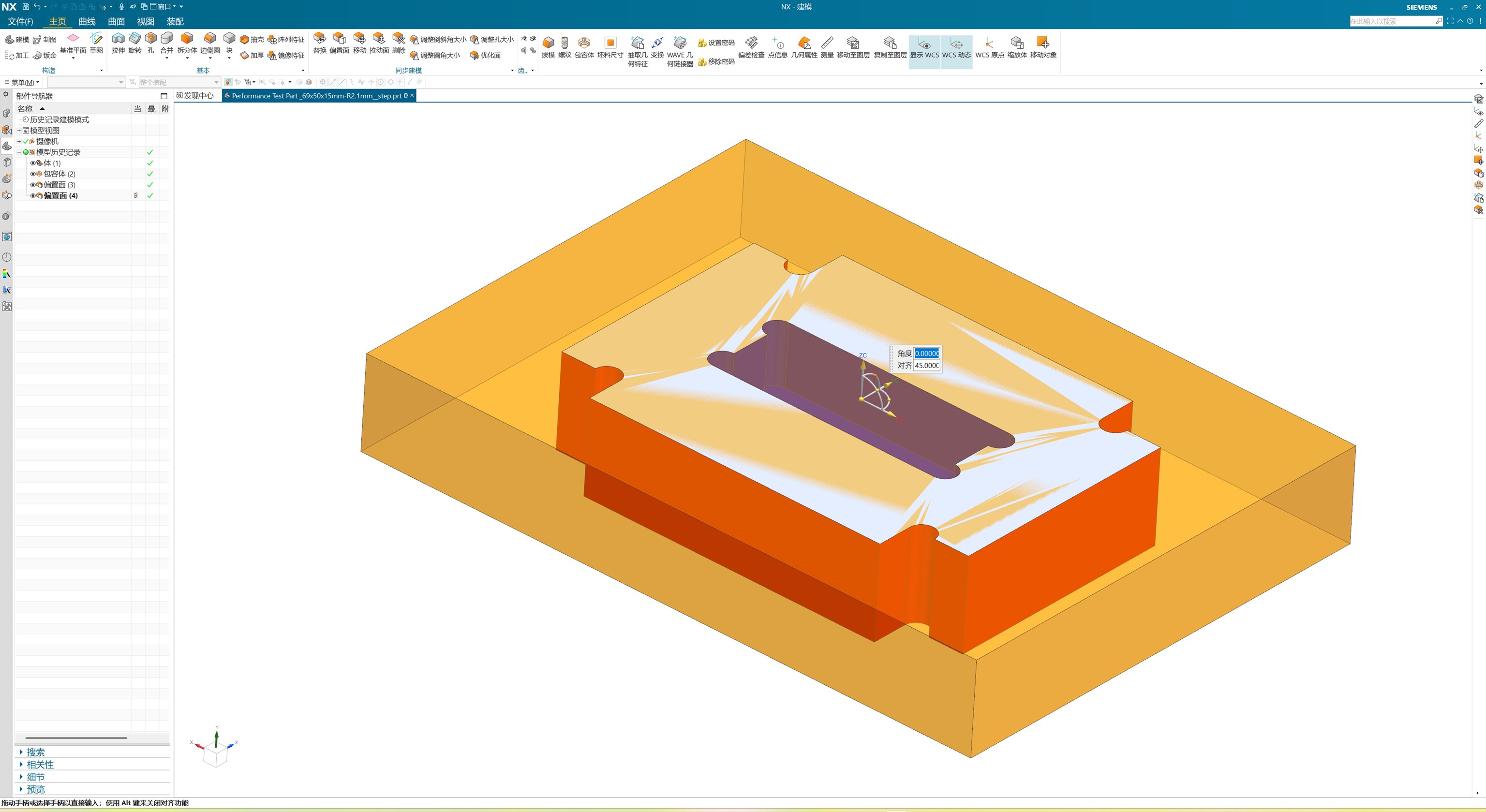
2.1 · Import the part and define the stock
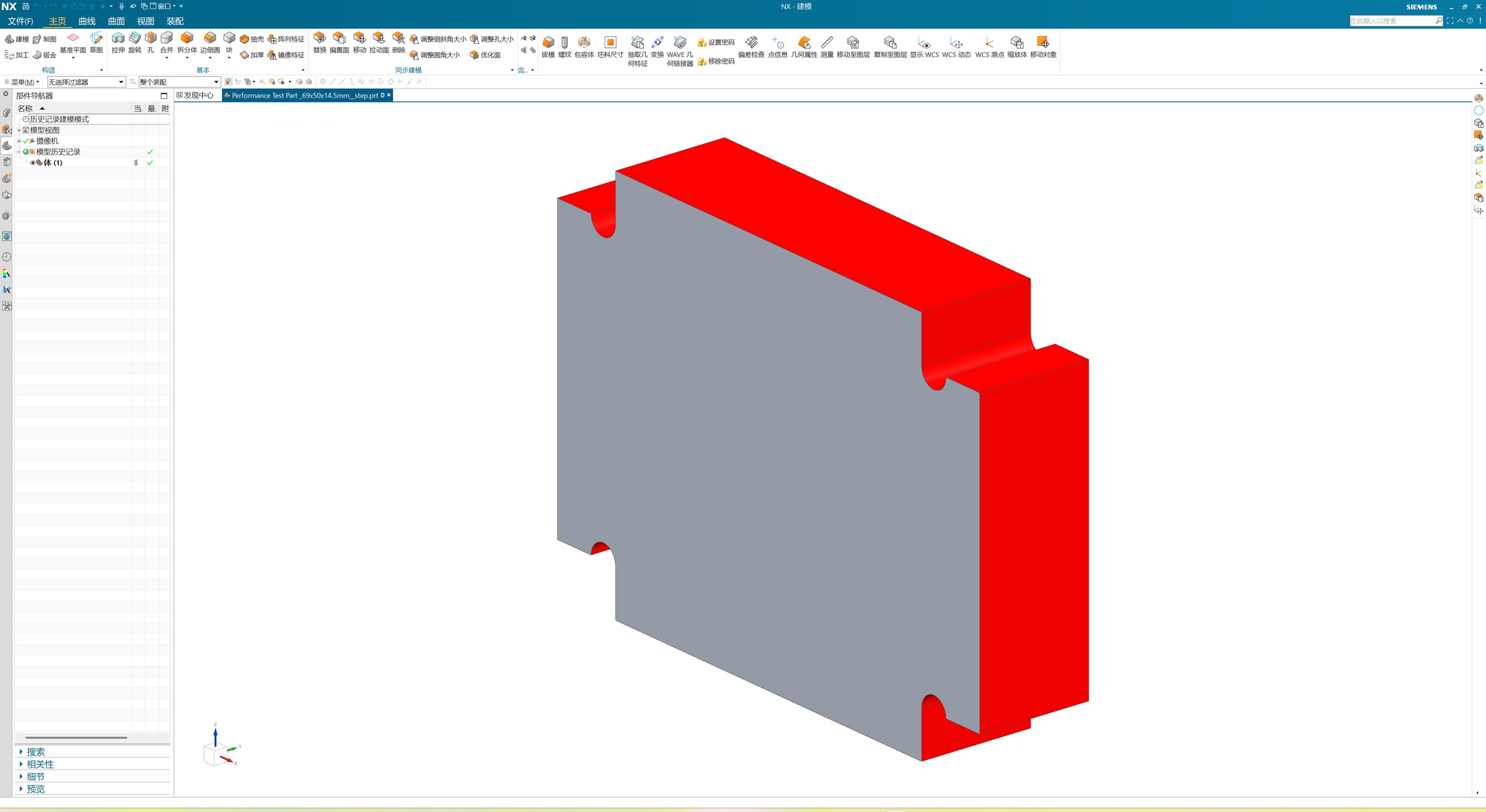
We imported Performance Test Part_69x50x14.5mm_step.prt, a test part measuring 69 × 50 × 14.5 mm. In the modelling module, a zero-offset bounding block defined the stock blank around the test body.
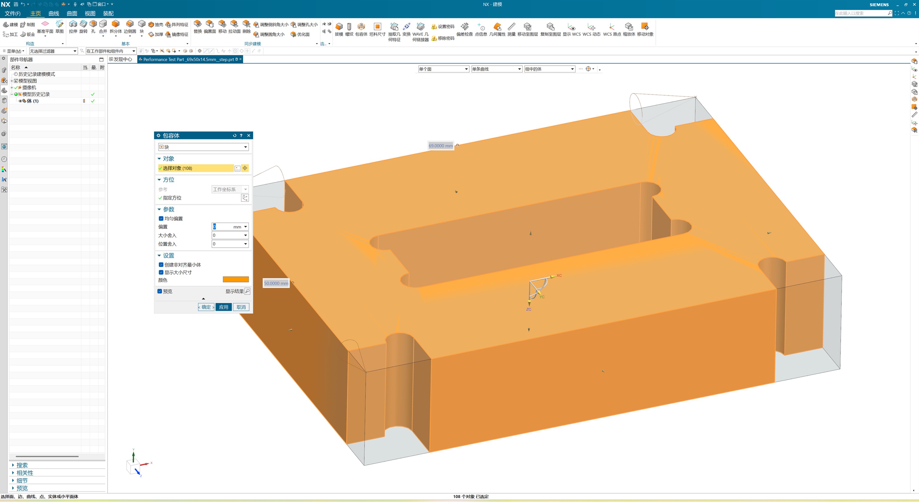
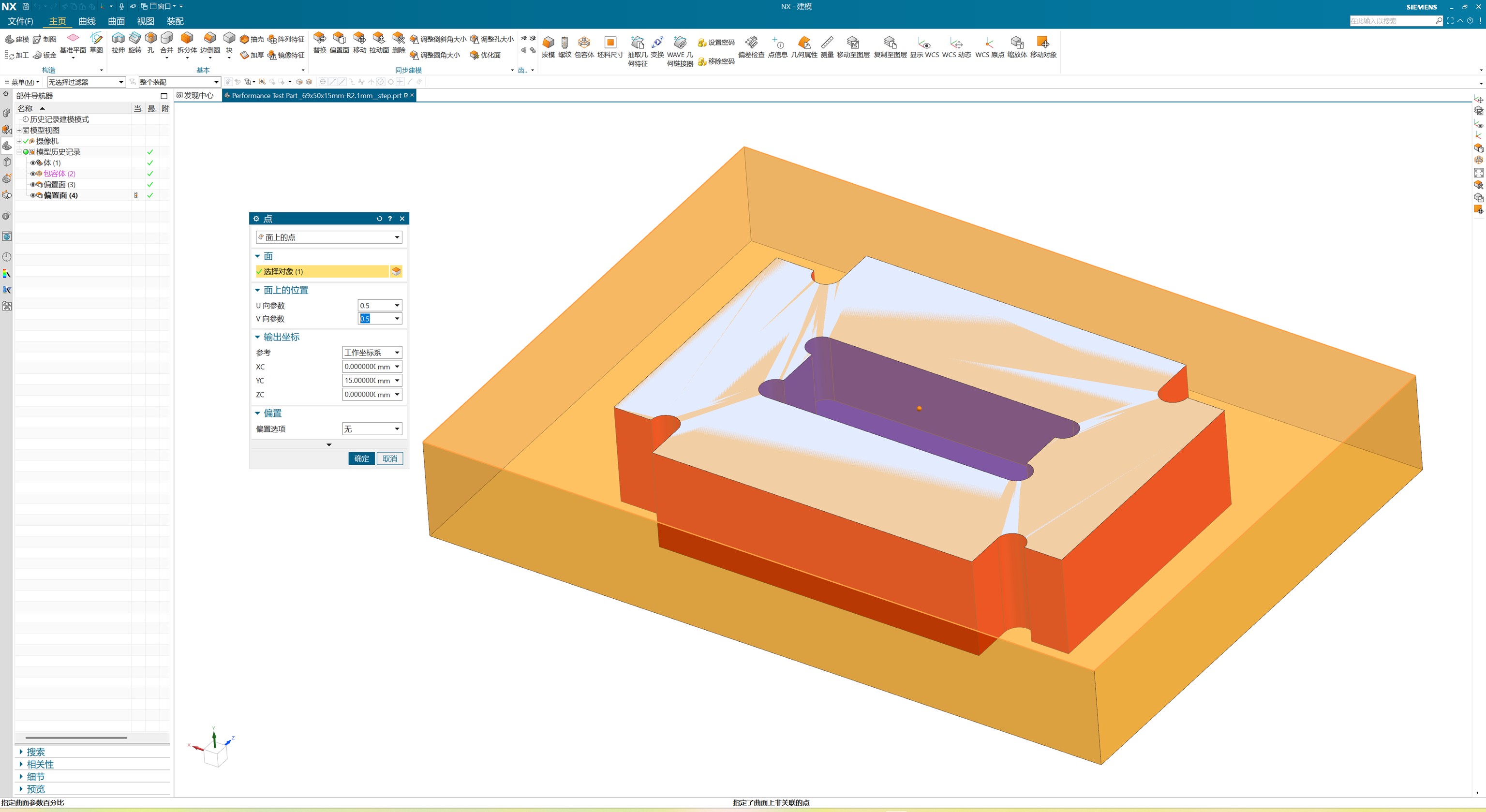
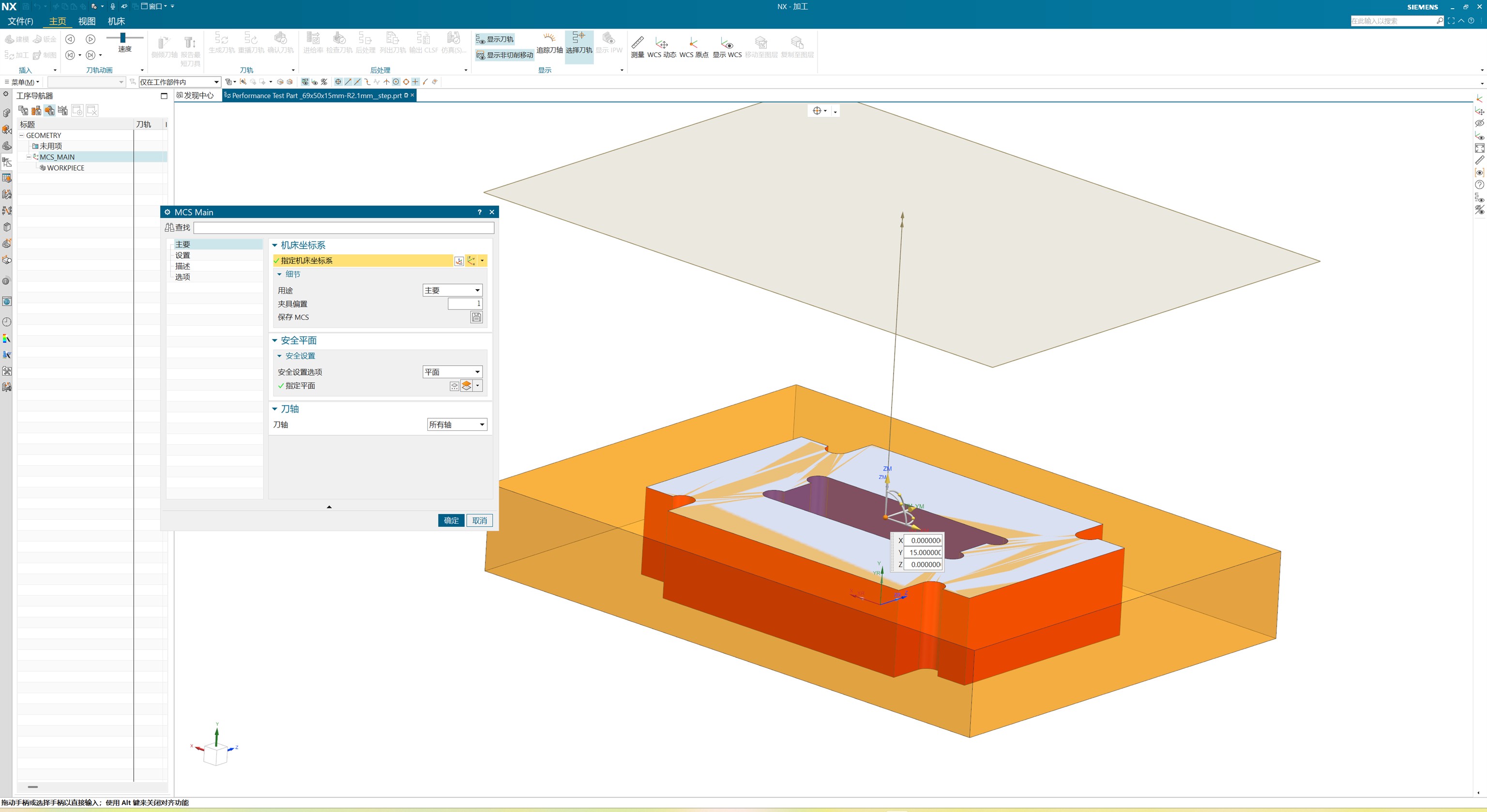
The machine coordinate system origin (X0, Y0, Z0) was placed at the top centre of the workpiece. A clearance plane 50 mm above the top face was defined for rapid traverse moves (G0).
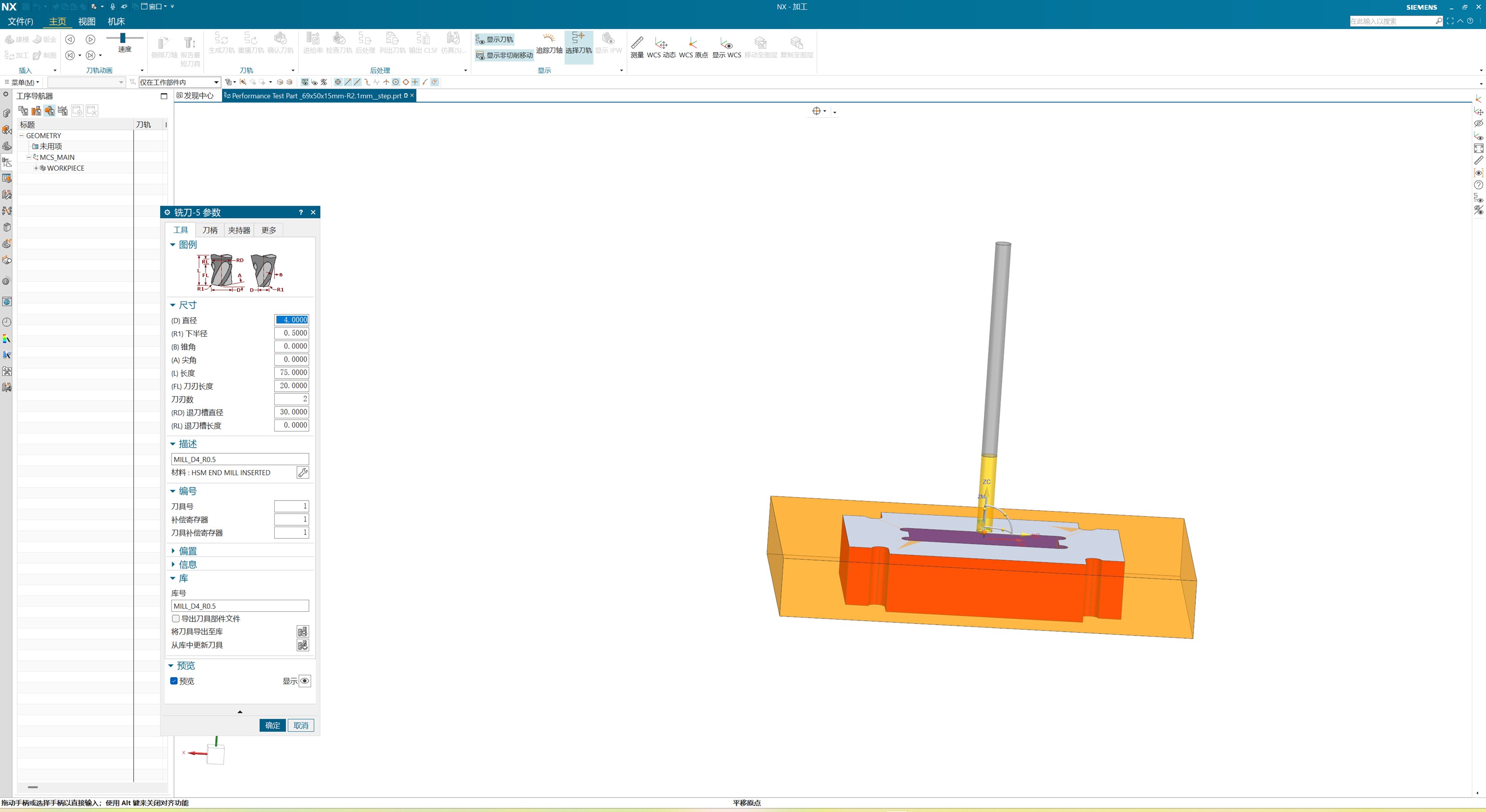
2.2 · Define the tools and operations
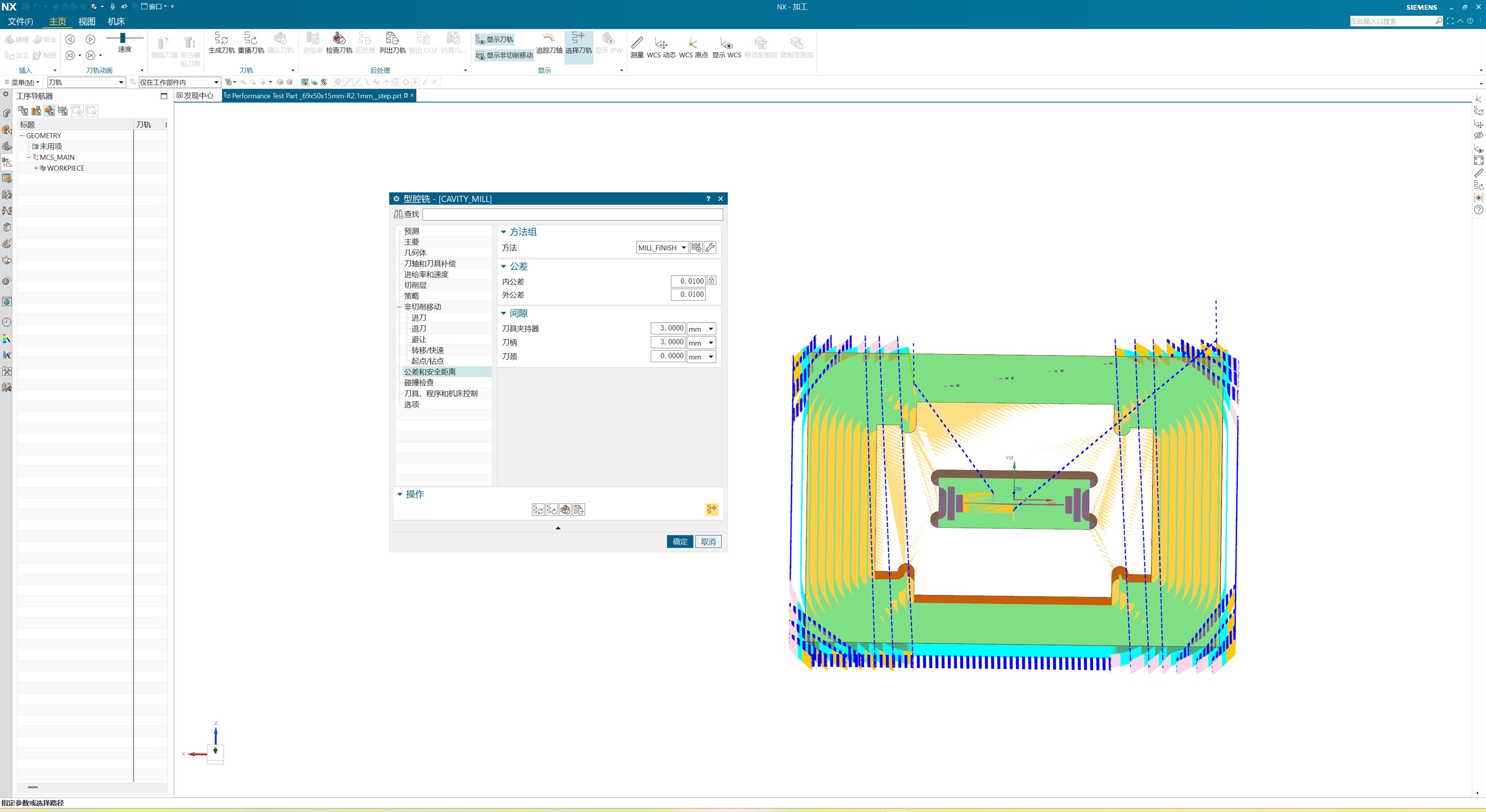
We created a 2.5D/3D milling program with two operations under the mill_contour type.
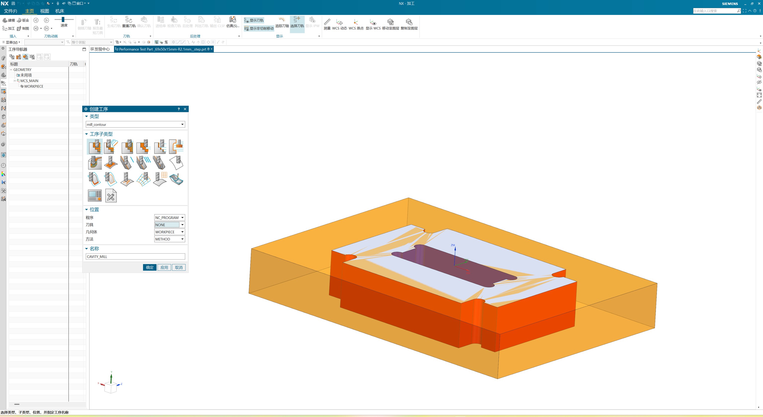
| Operation | Strategy & tool | Target geometry |
|---|---|---|
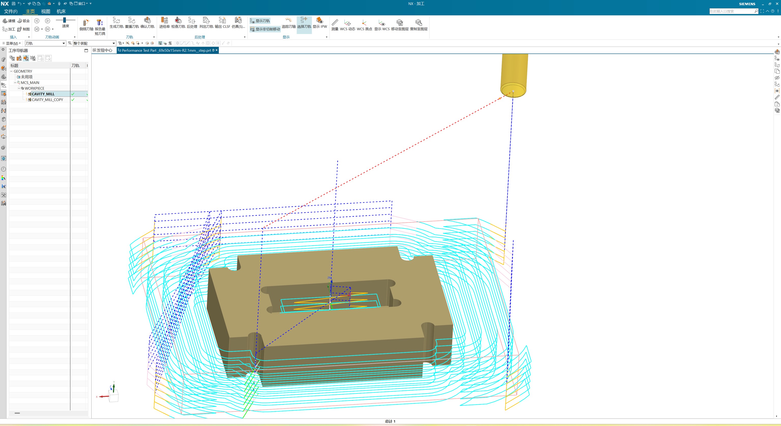
| CAVITY_MILL Roughing | Adaptive pocketing and clearing. Ø8 mm end mill, R0.5 corner radius, 2 flutes. | Internal slot/pocket and peripheral stepped contours. |
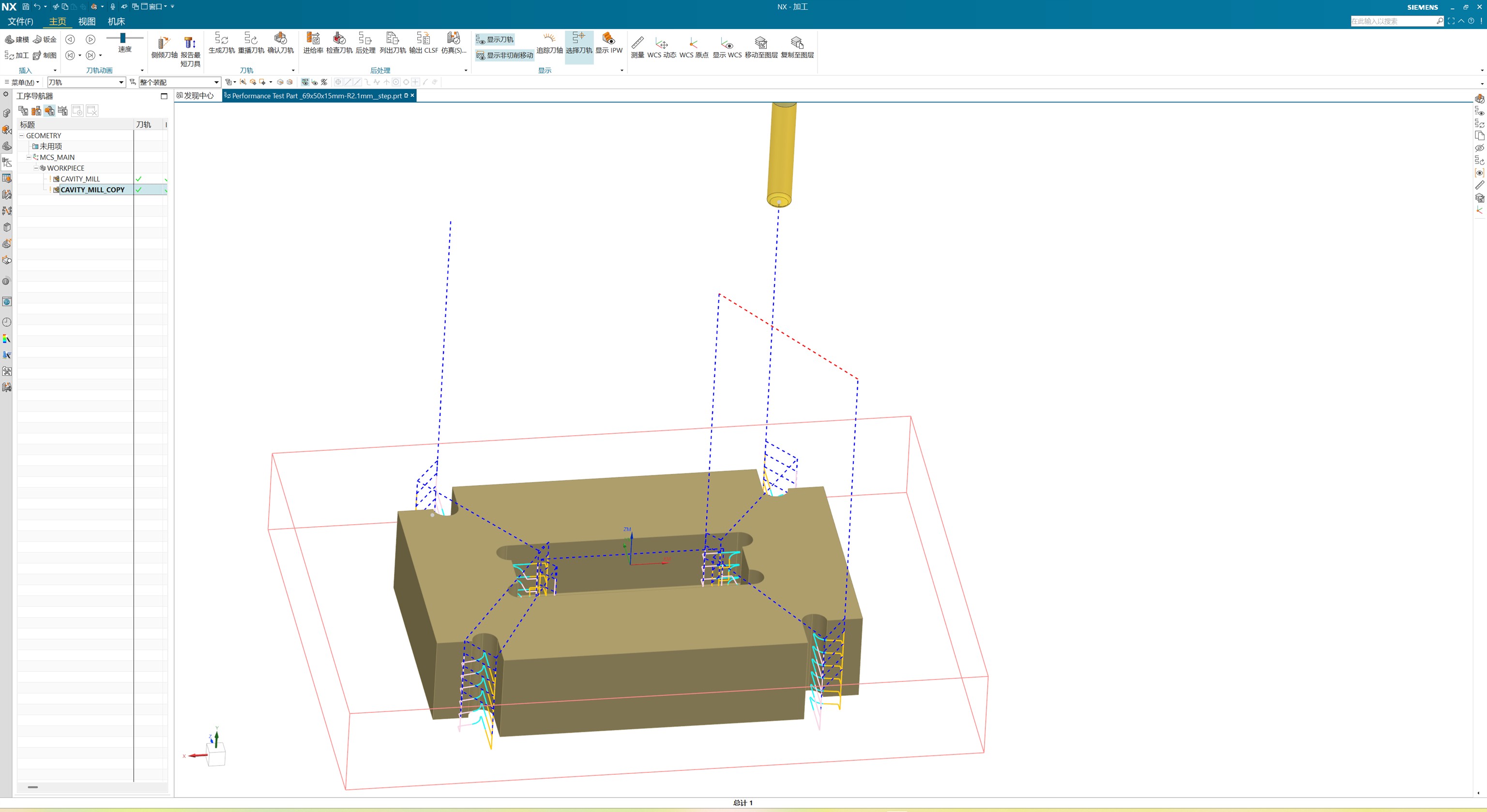
| CAVITY_MILL_COPY Finishing | Dedicated contour cleanup. Ø4 mm end mill, R0.5 corner radius, 20 mm flute length. | Final side-wall pass and corner-radius cleanup. |
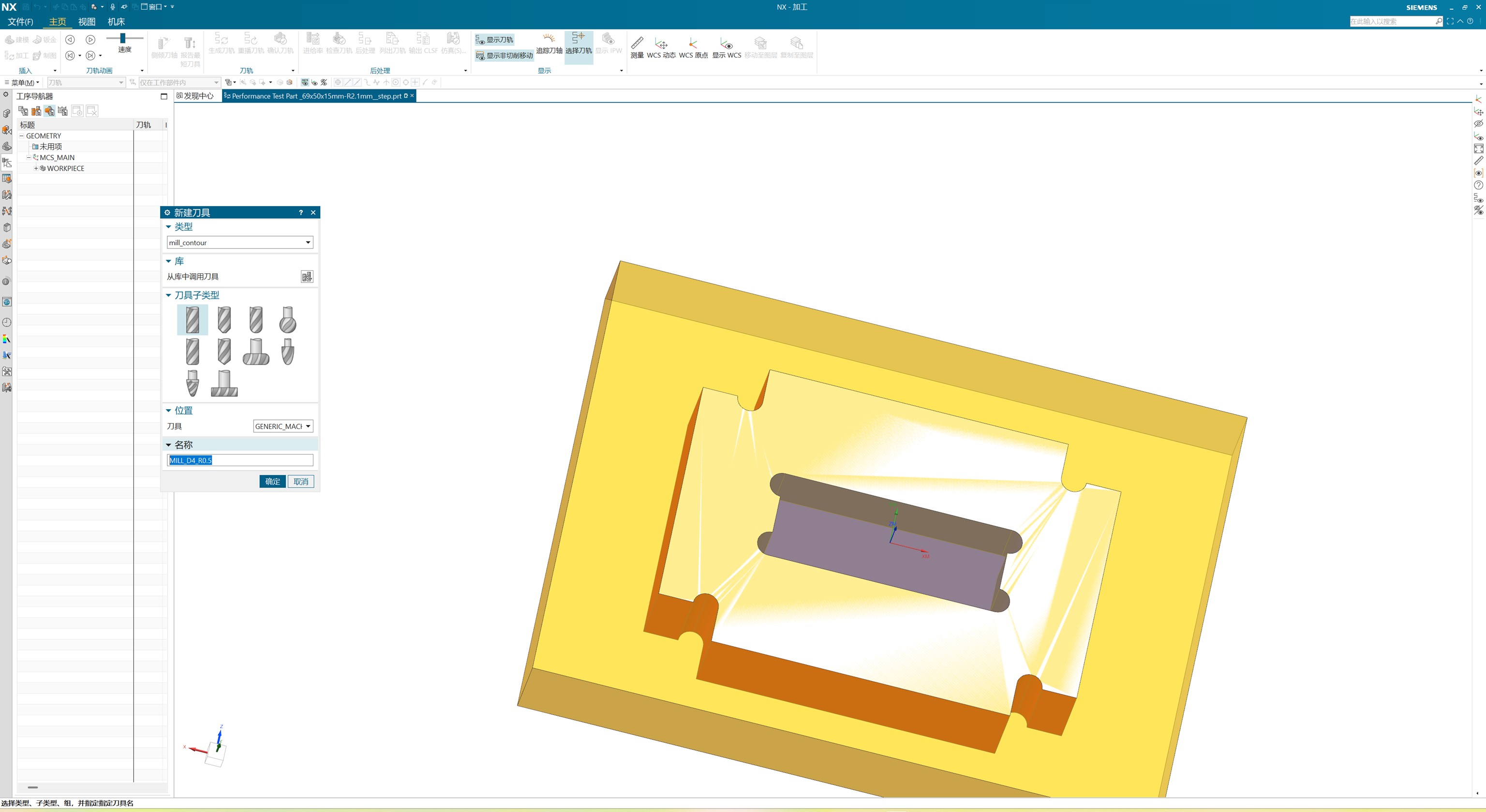
Helical/ramp entry moves used a 5° ramp angle, avoiding a direct vertical plunge into the solid wood.
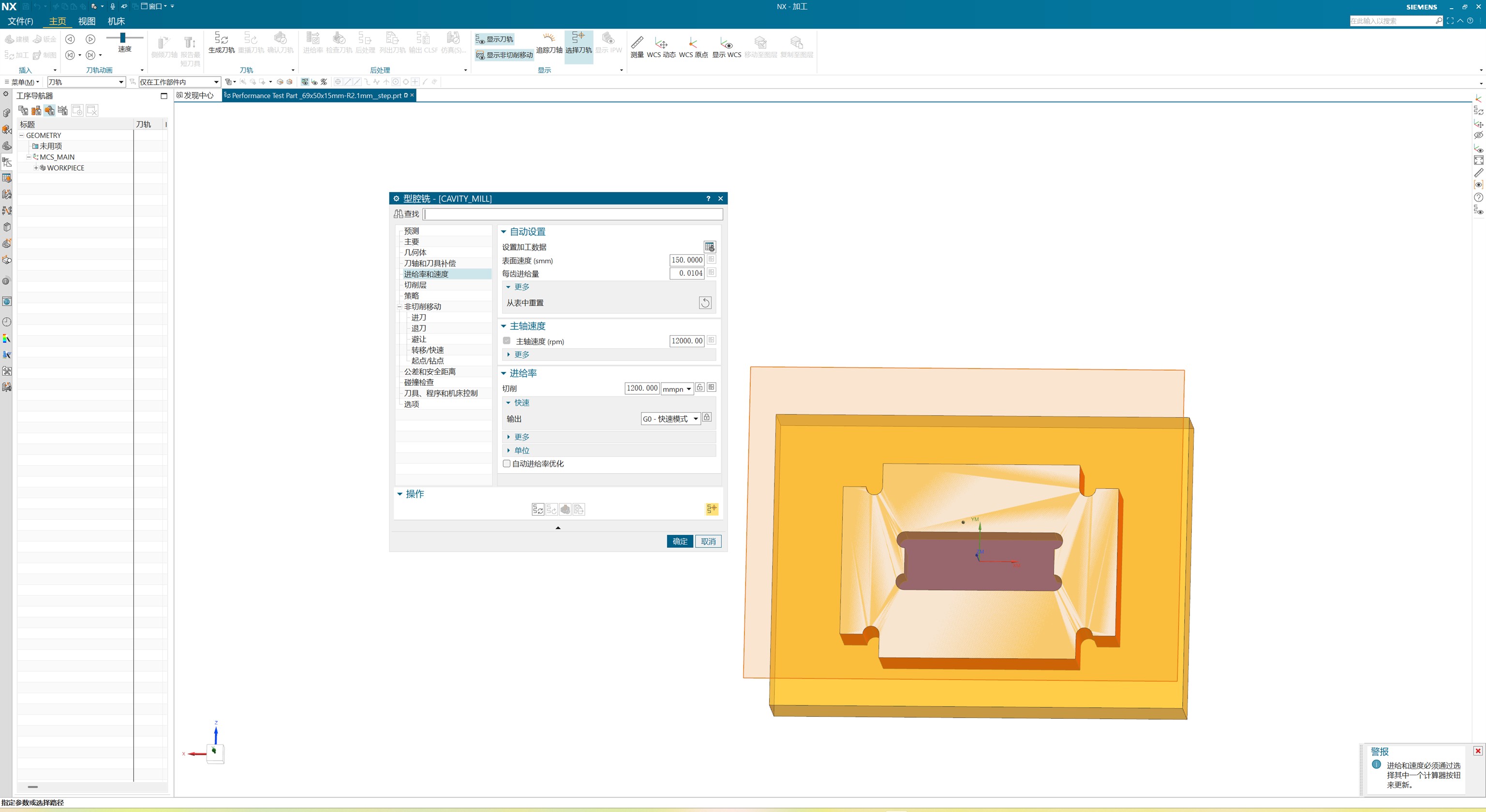
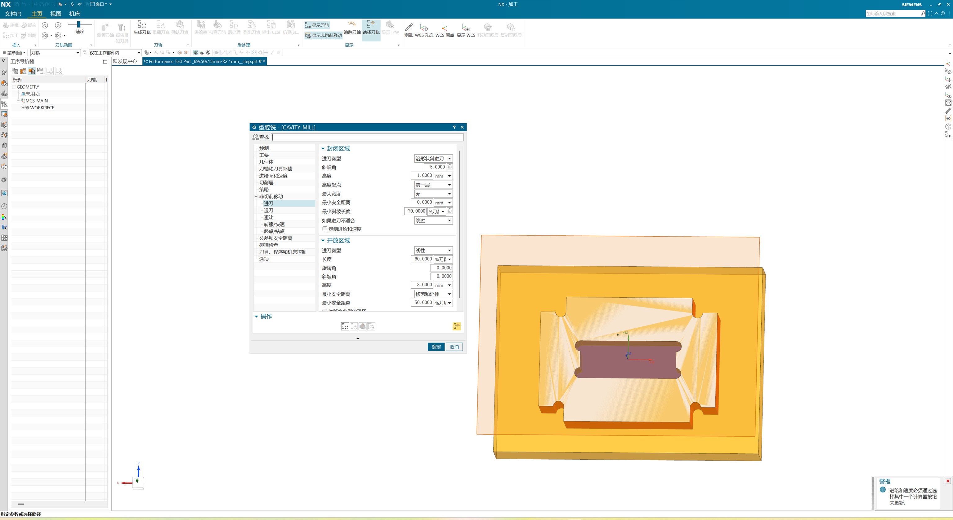
2.3 · Generate and simulate the toolpaths
We checked step-down levels, entry moves and containment boundaries for gouging and tool-shank collisions. A full 3D material-removal simulation let us inspect the in-process workpiece (IPW), including the corner dogbone reliefs and central pocket.
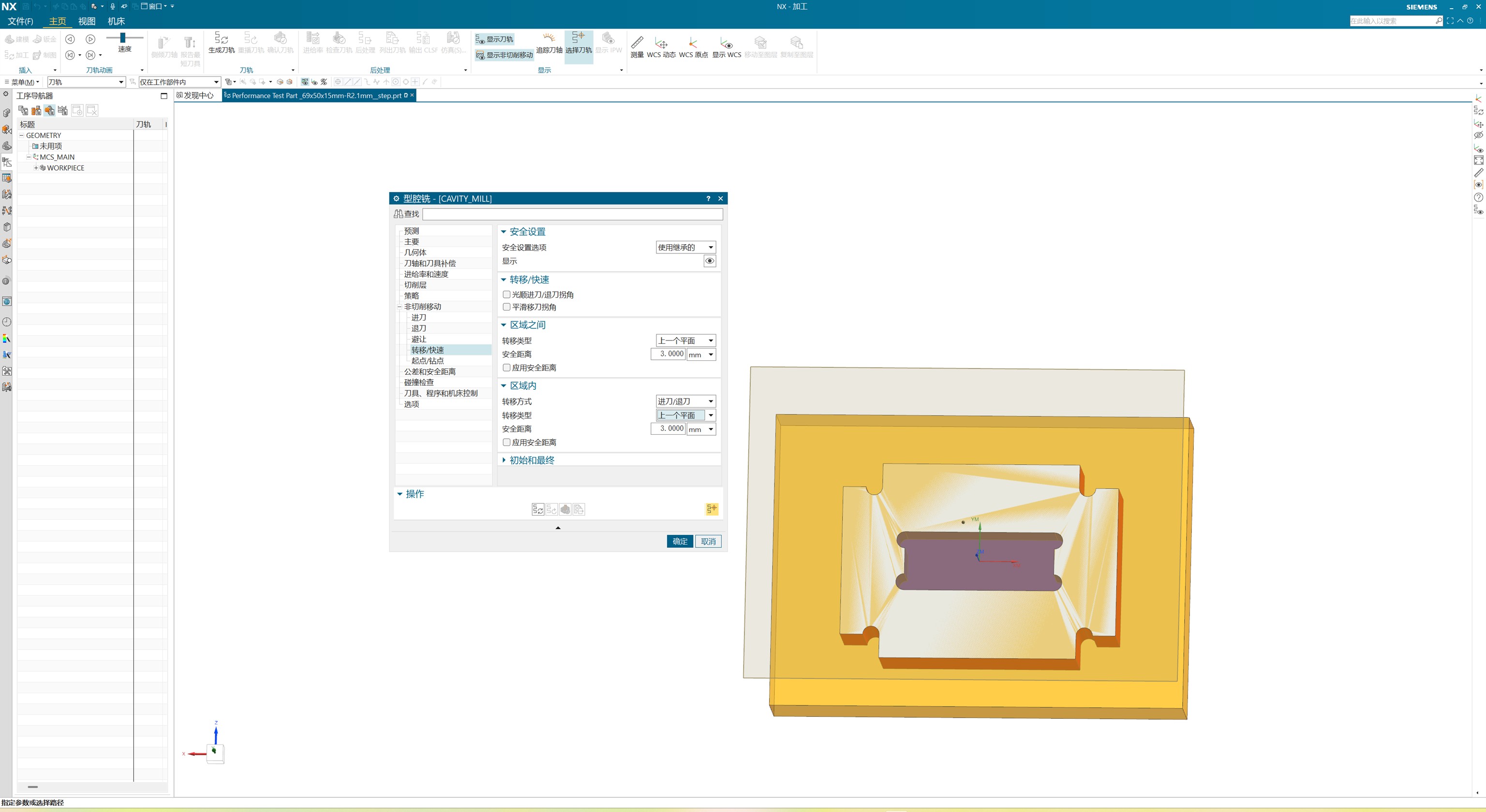
2.4 · Post-process and review the G-code
The new_post_Siemens_3_Axis post-processor generated ISO/Siemens .mpf programs for the LY1285L.
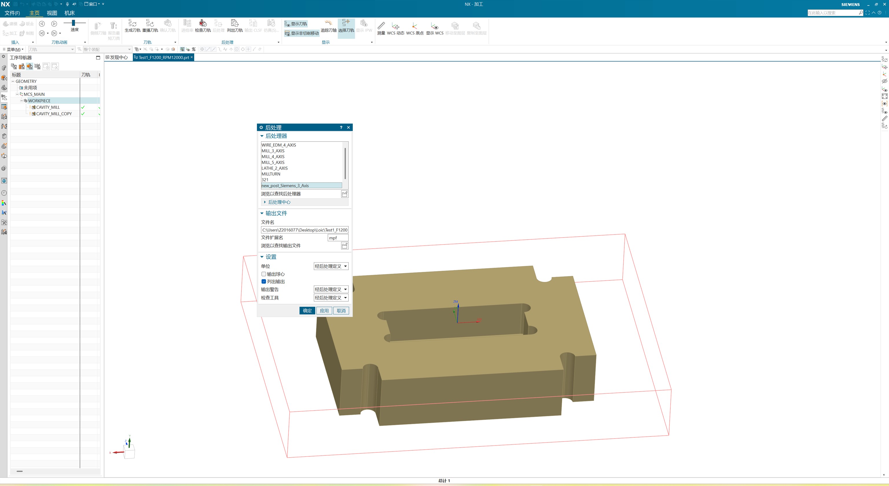
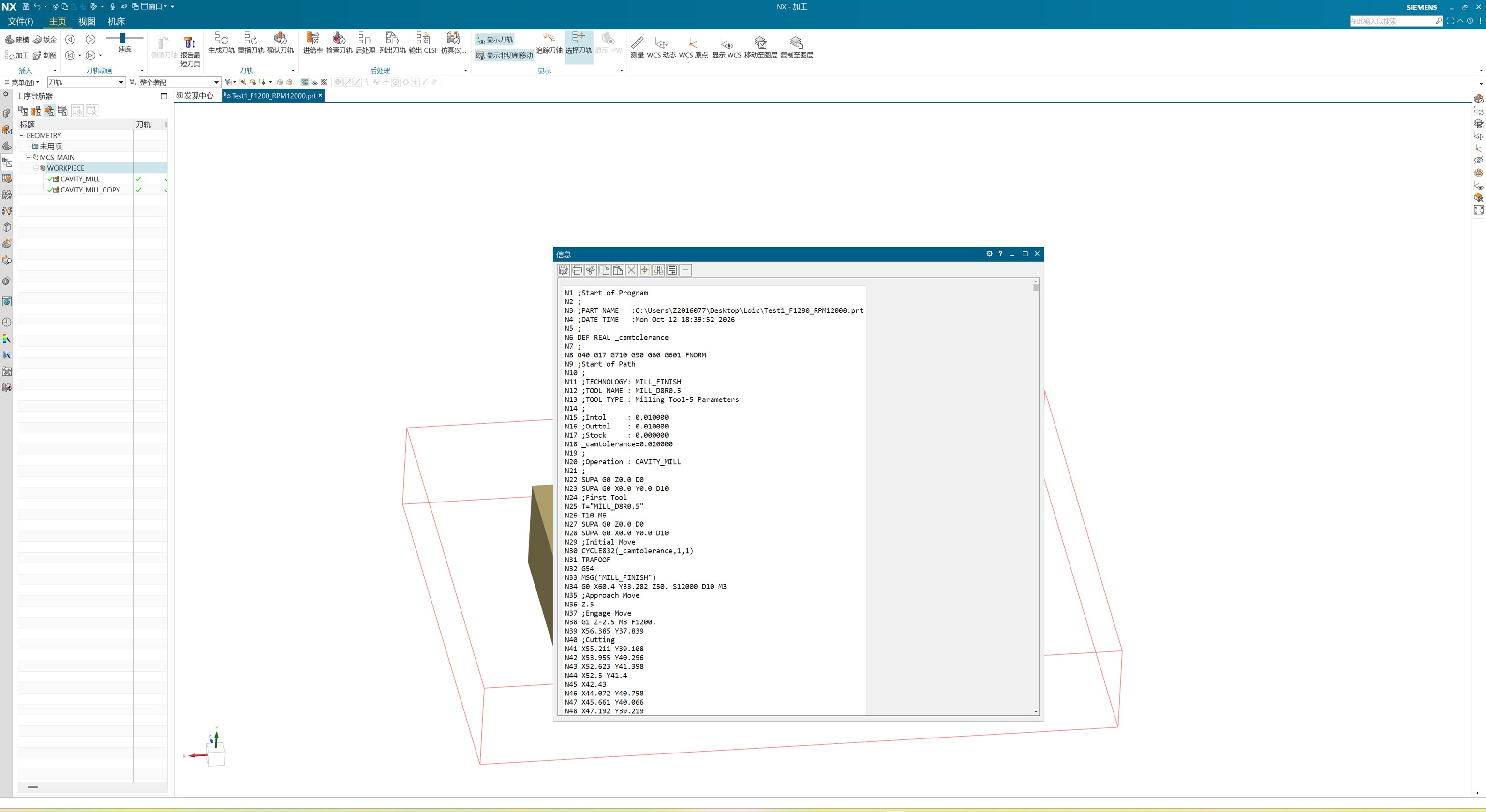
We reviewed the generated header and program blocks, including:
CYCLE832(_camtolerance,1,1)— high-speed cycle call.S12000 M3— spindle speed and direction, later updated for the speed tests.F1200— feed rate in the reviewed output.SUPA G0 Z0.0 D0— retract/tool-change block in the exported program.
03 / TOOLING & SETUP
Tooling, fixturing and alignment
Tool selection and setup
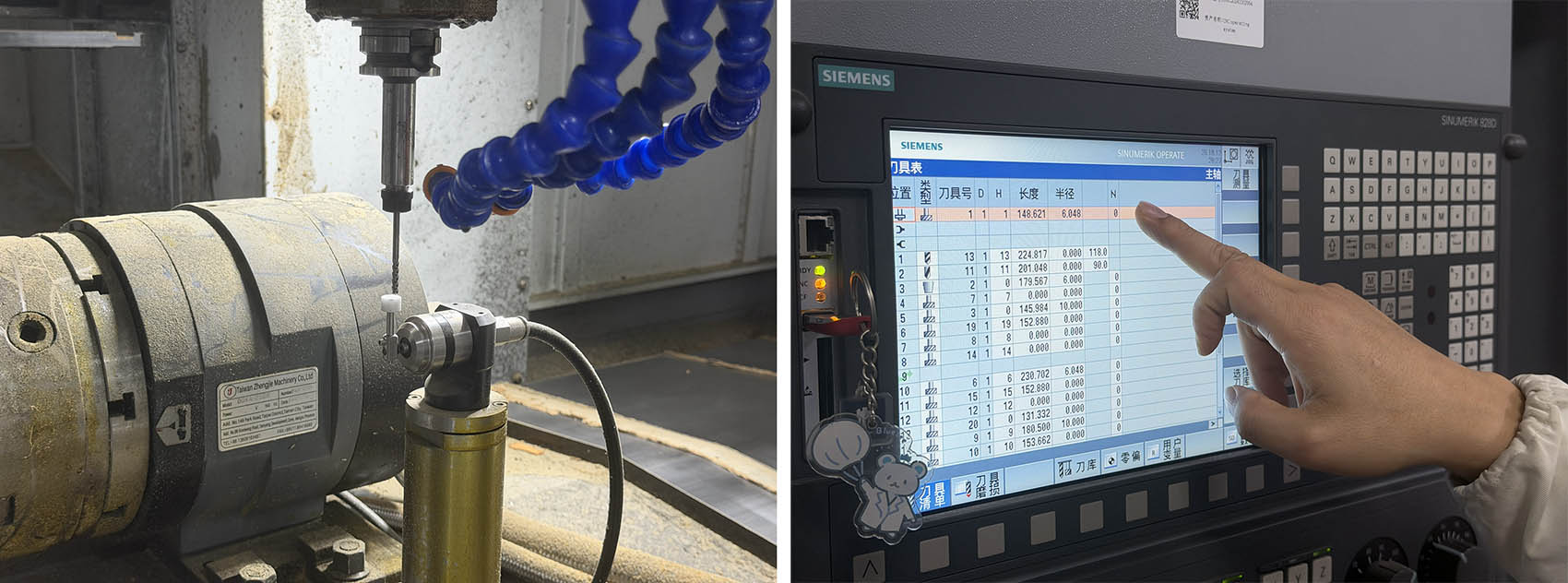
We prepared an Ø8 mm roughing end mill (R0.5 × 150 mm, as recorded in the tool notes) and an Ø4 mm finishing end mill (R0.5 × 20 mm). Each tool was mounted in an ER collet chuck, measured for stick-out, tightened with a collet wrench, loaded into the spindle or magazine and registered in the Siemens tool table.
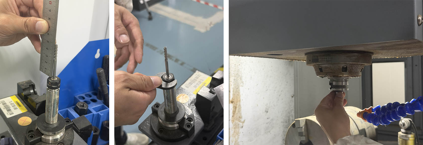
Tool length calibration
The built-in contact tool setter was used to calibrate tool length inside the machining chamber.
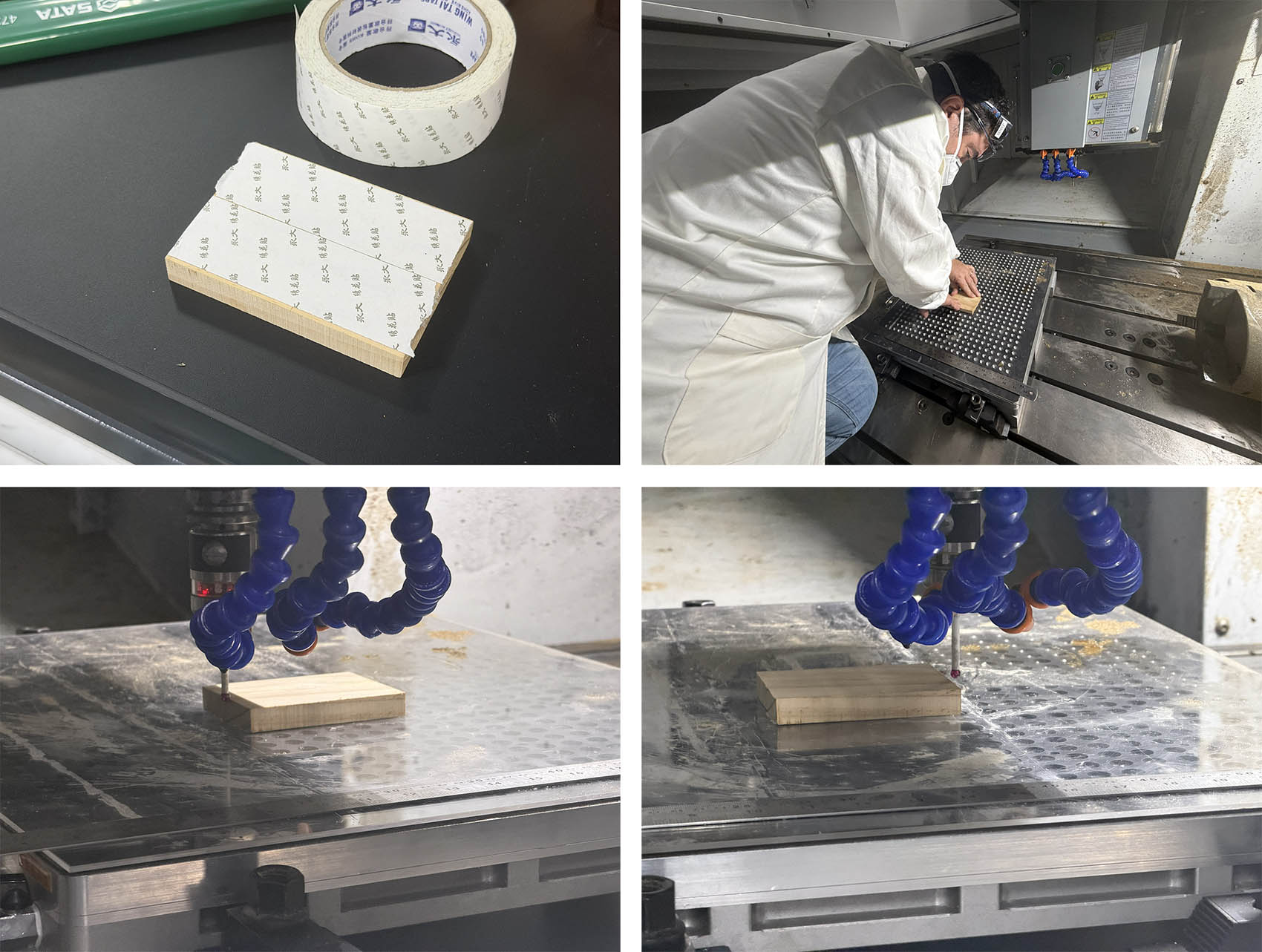
Fixturing and work coordinate zeroing
The timber blank was mounted on the vacuum fixture table with high-strength double-sided tape backing. We aligned the workpiece axes and set the X/Y/Z work coordinate system (G54) using the Renishaw touch probe.
04 / CONTROLLER VERIFICATION
Check the program at the machine
Before cutting, we transferred the G-code by USB and checked it in the SINUMERIK 828D’s graphical simulation mode. We reviewed clearance planes, plunge-entry points, step-downs and boundary containment.
05 / TEST RESULTS
Eight cuts. A cleaner finish.
We machined eight identical profile blocks in reclaimed solid wood, varying spindle speed and feed rate to compare tear-out, vibration, finish and cutting time.
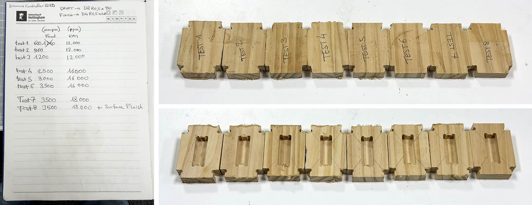
| Test | Feed mm/min | Spindle rpm | Observations |
|---|---|---|---|
| 01 | 600 | 12,000 | Conservative feed; fibrous tear-out along pocket edges and burning on external corner edges. |
| 02 | 960 | 12,000 | Improved chip evacuation; some edge fuzziness and burning remained. |
| 03 | 1,200 | 12,000 | Stable cutting sound and a clean contour; slight chatter on the pocket floor. |
| 04 | 2,500 | 16,000 | Improved edge definition and chip formation, with no burning observed. |
| 05 | 3,000 | 16,000 | Clean side walls, reduced cycle time and a smooth pocket bottom. |
| 06 | 3,500 | 16,000 | Good speed/quality balance; a minor edge burr on the end grain. |
| 07 | 3,500 | 18,000 | Crisp edges, good chip size and no chatter observed. |
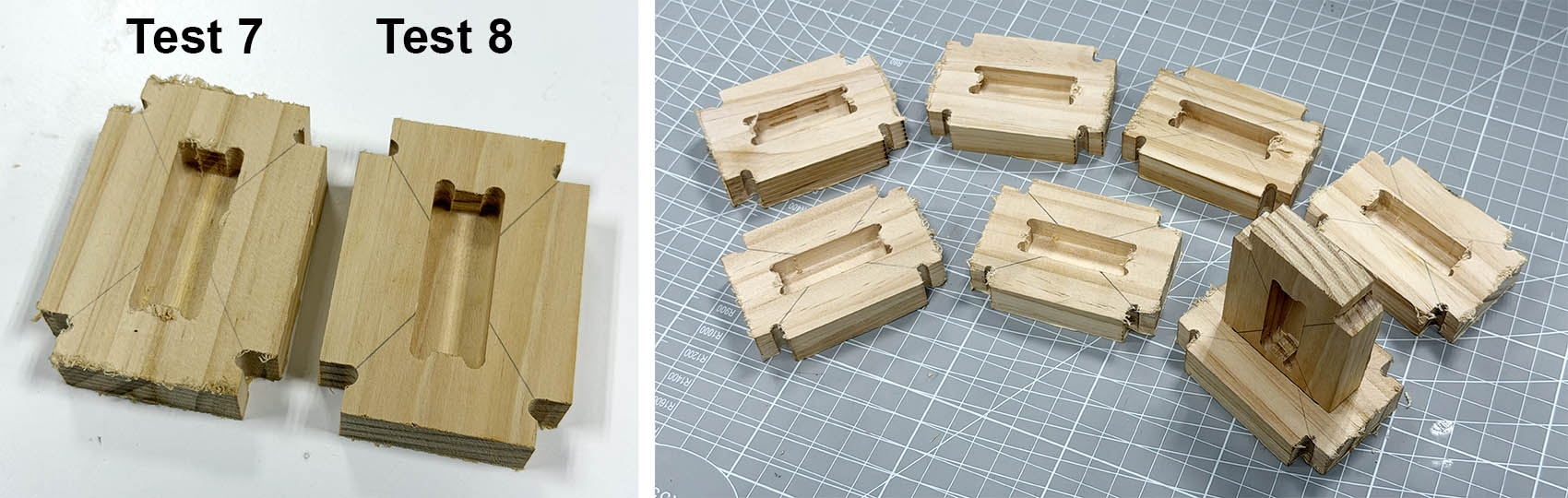
| 08Best observed | 3,500 | 18,000+ finishing pass | A dedicated finishing pass produced the sharpest corners and smoothest pocket floor in this test series. |
These are the group’s observations for this material, tooling and setup. The finishing pass is shown separately from spindle speed.
06 / WHAT WE LEARNED
Balance the cut, then refine the surface
Speed and feed work together
Across our tests, moving from 12,000 rpm / 600 mm/min towards 18,000 rpm / 3,500 mm/min improved chip formation and reduced the rubbing and burning seen at the first settings.
A separate finishing pass made the difference
Test 8 gave the best observed finish. The group reported that a light, dedicated finishing pass removed the end-grain tear-out seen in earlier cuts and improved the pocket floor. This informed the CAM strategy for our individual projects.
07 / DESIGN FILES
Download the test part
The supplied STEP model is available for inspecting the test geometry and preparing CAM operations.
STEP · 96 KB
Performance Test Part
69 × 50 × 15 mm · R2.1 mm
This download is labelled as the 15 mm / R2.1 mm version. The earlier CAM import notes above refer to a 14.5 mm version.
← Back to group assignments