In the group assignment, we explored how to operate the MultiCam 3000 CNC machine. We tested several parameters including runout, alignment, fixturing methods, speeds, feeds, materials, and toolpaths. Through these tests, we observed how each parameter affects the machining process and compared different configurations to determine the best settings for the material and cutting conditions.
Lab safety training is essential before operating high-speed CNC machines. It covers how to work safely, understand potential risks, and prevent accidents in the lab.
◉
Eye protection
Wear protective glasses at all times to avoid chips or debris projected during machining.
>>>
Hearing protection
Use hearing protection to reduce noise exposure from the spindle and router during operation.
✕
No loose clothing
Avoid loose clothing, jewelry, or accessories that may get caught in moving parts of the machine.
∅
No touching spindle
Never touch the spindle, tool, or cutting area while the machine is operating — even if it appears to have stopped.
⊞
Gloves — when to use
Use gloves only when handling material or cleaning the area. Remove them before operating the machine.
◎
Dust mask
Use a mask when machining materials that produce dust, such as MDF or composites.
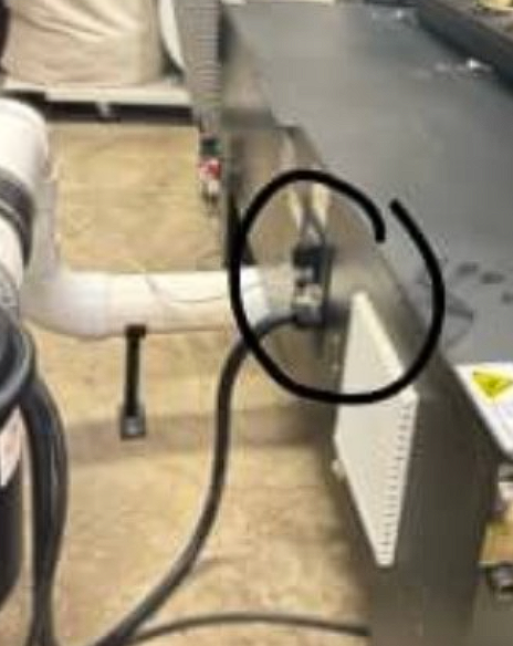
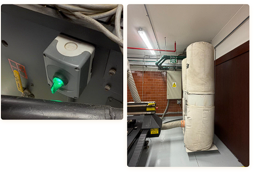
Img 5 — Dust extraction connectionHighlighted circle shows the hose connection point for the external dust extraction system at the base of the MultiCam 3000. Active during all machining operations to capture chips and fine dust particles — essential when cutting plywood and MDF.Img 6 — Power switch & dust collectorLeft: machine power switch with green indicator light — confirms the machine is powered and ready. Right: external dust collection bag unit beside the MultiCam 3000 — collects all material removed during machining to keep the lab environment safe.
Equipment
Machine Specifications — MultiCam 3000
3-axis CNC Router · 1270 × 2540 mm working area
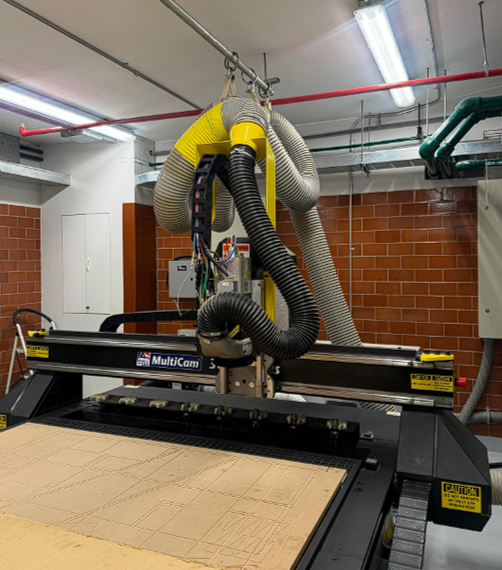
Img 1 — MultiCam 3000 Series CNC RouterFull view of the machine in the Fab Lab ULima space. Yellow dust extraction hose visible overhead. Gantry spanning the full 1270 × 2540 mm working area. Plywood sheet on sacrificial bed showing previous machining marks. Emergency stop visible on the right side panel.
The MultiCam 3000 Series CNC Router is the machine used for this assignment. It allows large-scale machining of materials such as plywood, MDF, plastics, and composite materials using computer-controlled toolpaths.
Specification
Value
Machine Model
MultiCam 3000 Series CNC Router
Number of Axes
3-axis (X, Y, Z)
Working Area
Approximately 1270 mm × 2540 mm
Drive System
Rack and pinion (X, Y) · Ball screw (Z)
Spindle Speed
Up to 24,000 RPM
Tool Type
End mill router bit
Dust Collection
External dust extraction system
Work Surface
Sacrificial bed
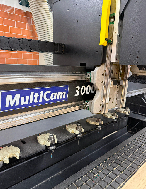
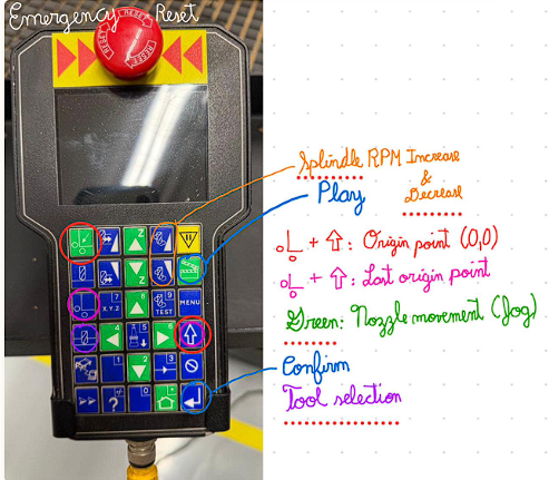
Img 2 — Spindle & fixturing clamps detailClose-up of the MultiCam 3000 gantry showing the spindle assembly with brush guard, tool collet, and the mechanical clamps used to hold the material sheet to the sacrificial bed. Clamp positions must be considered when setting the origin margin.Img 3 — Handheld pendant controller — annotatedEmergency stop (red) at top. Key functions annotated: Play (start job), Spindle RPM increase/decrease, Green arrows = Nozzle movement (Jog), Confirm / Tool selection buttons. Lower-left + Up arrow = Set origin point (0,0). Lower-left + Down arrow = Load last origin point.
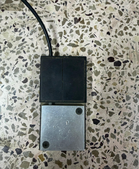
Img 4 — Foot pedalTwo-button foot pedal used to control vacuum fixturing or confirm operations on the MultiCam 3000 without leaving the machine area. Allows hands-free confirmation during material loading and fixturing steps.
Cutting Parameters
For machining the plywood sheet (18 mm thickness), the following cutting parameters were selected to achieve stable cutting and avoid burning the material.
Parameter
Value
Material
Plywood (Triplay) — 18 mm thickness
Tool
End mill — 6 mm diameter
Spindle speed
18,000 RPM
Feed rate
120 mm/min
Cut depth per pass
6.17 mm
Number of passes
3 passes
Total cut depth
18.5 mm
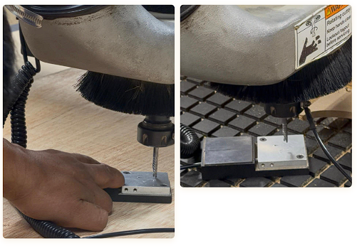
Img 7 — Z-probe tool height calibrationLeft: hand-placing the Z-probe plate under the tool for automatic height calibration. Right: tool positioned over the Z-probe sensor resting on the sacrificial bed surface. The machine lowers the tool until contact is detected — this sets Z=0 and compensates for tool length differences automatically, directly affecting runout and depth accuracy.
Tabs / Bridges Test
One of the important tests performed was the use of tabs (bridges). Tabs are small connections left in the toolpath that keep the piece attached to the material sheet during machining. Their purpose is to prevent the piece from moving or being ejected when the final contour is cut. After machining, the tabs are manually removed during the finishing stage.
⌇
Why tabs are needed
When the CNC cuts the final contour, the part becomes fully free from the sheet. Without tabs, the piece can move or spin into the tool, causing damage or a safety hazard.
⊡
How tabs work
Small uncut bridges are left at intervals around the contour. They hold the part in place throughout the job and are broken or cut off by hand after the machine finishes.
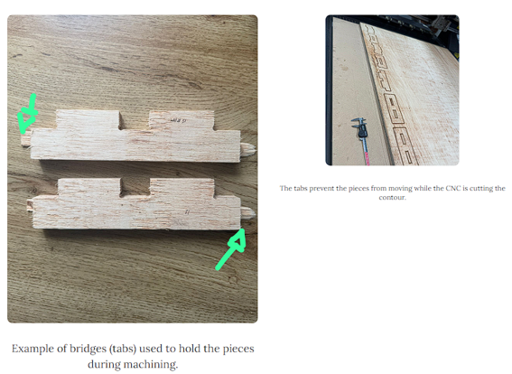
Img 18 — Tabs (bridges) on machined piecesLeft: two plywood pieces removed from the sheet — green arrows point to the tab break-off marks where the bridges held the parts during machining. Right: CNC actively cutting the board contour — the tabs visible along the edge keep the piece stationary until the job finishes. Caption confirms: tabs prevent pieces from moving while the CNC is cutting the contour.
Press-fit Tolerance Test
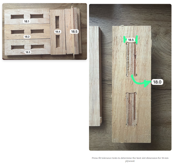
To determine the correct press-fit tolerance, several test slots were designed before machining the final model. Tests started at 18.0 mm and increased gradually to 18.5 mm in 0.1 mm increments, allowing observation of how tight or loose the joint becomes at each step.
18.0
Very tight — difficult to assemble
18.1
Tight — requires force
18.2
Snug — good friction fit
18.3
Press-fit — firm and clean
18.4
Loose — slides easily
18.5
Too loose — no friction
Img 19 — Physical press-fit tolerance test — 18.1 to 18.5 mmLeft: five machined slot pieces labeled 18.1 through 18.5 mm with their corresponding inserts — each slot is 0.1 mm wider than the last. Right: assembled view showing 18.5 mm (top, very loose — slides freely) vs 18.0 mm (bottom, very tight — barely accepts the insert). The best press-fit result was found at 18.3 mm, confirming the tolerance range for 18 mm plywood on this machine.
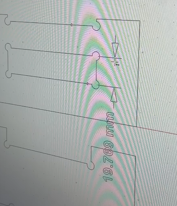
Img 14 — Press-fit tolerance sketch — 19.769 mm dimensionFusion 360 sketch showing side-by-side comparison of the three corner relief geometries (T-Bone top, Semi Dog-Bone center, Dog-Bone bottom) with the joint dimension annotated at 19.769 mm. This comparative view was used to verify that each relief strategy maintains correct joint width before generating the DXF for the CAM software.
Individual Contribution
Internal Corner Relief Strategies
My individual contribution focused on modeling the different corner relief strategies in Autodesk Fusion 360, creating parametric sketches to control key dimensions, and running simulation tests to observe how the joints behave during assembly.
Why Corner Relief is Necessary
When machining parts with a CNC router, internal corners cannot be perfectly sharp because the cutting tool is cylindrical. This leaves a radius in pockets or slots — when assembling square components, the rounded internal corner prevents the part from fully seating. Corner relief strategies add small circular cuts at internal corners to create enough clearance for square parts to properly assemble.
Img 10 — Fusion 360 — three corner relief sketchesSide-by-side parametric sketches for the three strategies in Fusion 360. Left column: T-Bone relief — circle center aligned to one edge. Center column: Semi Dog-Bone — circle offset so corner touches the circumference. Right column: Dog-Bone — circle centered exactly on the corner. All sketches are driven by shared user parameters (tool diameter, material thickness).
Strategy 01
Dog-Bone
Center coincides with corner
Relief extends diagonally outward
Maximum clearance
Most visible relief on finished part
Strategy 02
T-Bone
Center aligned with one edge
Relief on one axis only
Less material removed
Cleaner visual result than dog-bone
Winner ✓
Strategy 03
Semi Dog-Bone
Circle offset from corner
Corner touches circumference, not center
Most discrete relief
Best aesthetic finish
Sufficient clearance for assembly
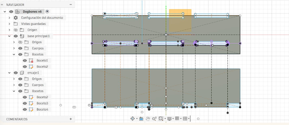
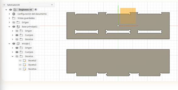
Img 12 — Dogbones v6 — sketch with joint slotFusion 360 sketch view of the combined Dog-Bone model (Dogbones v6): base piece with three relief types visible on the top bar, and the mating encaje (insert) piece below showing the corresponding slot geometry. Navigator tree shows separate bodies and sketch layers for each component.Img 13 — Dogbones v6 — 3D solid model3D solid view of the final combined test piece: top = base principal with all three dog-bone reliefs cut in; bottom = encaje (mating insert) with the corresponding tab geometry. Orange highlight shows the assembly origin reference. This is the model used to generate the DXF for enRoute.
Parametric Simulation in Fusion 360
Using parametric design ensures that if the tool size or material changes, the geometry updates automatically without needing to redesign the model from scratch. All three corner relief strategies were modeled this way.
⌀
Parameters used
Tool diameter: 6 mm
Material thickness: 9.4 mm
Joint dimensions based on tool radius
⊥
Sketch constraints
Project Geometry
Coincident Constraint
Tangent Constraint
Construction Lines
Midpoint Constraint
Test 1
Individual Bone Tests
Each corner relief strategy was analyzed individually. The mating parts were designed so they engaged with approximately half of the bone relief — allowing observation of how each strategy affects fitting and clearance independently before combining them.
Order tested: T-Bone · Semi Dog-Bone · Dog-Bone
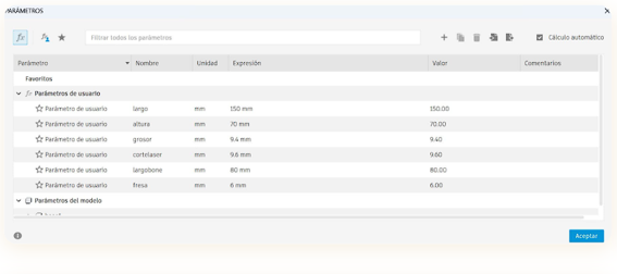
Img 8 — Fusion 360 user parameters — Test 1 (Individual bones)Parameters panel showing Test 1 configuration: largo = 150 mm, altura = 70 mm, grosor = 9.4 mm, cortelaser = 9.6 mm, largobone = 80 mm, fresa = 6 mm. These values drive the individual bone test pieces — each piece tests one corner relief strategy in isolation with approximately half-bone engagement.
Test 2
Combined Bone Test
A single test board containing all three corner relief strategies was designed so that joints engaged with more than half of the bone relief. This allowed direct comparison of all strategies under slightly different fitting conditions on the same machined piece.
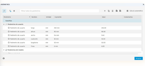
Img 9 — Fusion 360 user parameters — Test 2 (Combined bone)Parameters panel showing Test 2 configuration: largo = 250 mm (wider piece), altura = 80 mm, ancho = 9.4 mm, cuaŀcorte = 92 mm, largobone = 50 mm, fresa = 6 mm. Larger dimensions accommodate all three relief strategies side by side on a single base piece — enabling direct comparison with consistent machining conditions.
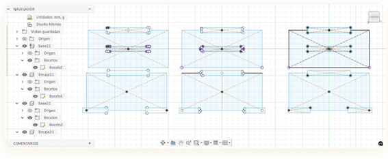
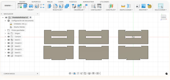
Img 11 — Fusion 360 — 6-piece combined test solid model3D solid view of all six components for the combined bone test: three base pieces (top row) each with a different corner relief strategy, and three corresponding encaje (insert) pieces (bottom row). This layout mirrors the enRoute CAM positioning before generating G-code for the MultiCam 3000.
Fusion 360 → Inventor → MultiCam Workflow
The complete workflow from parametric CAD model to physical machined part.
01
Fusion 360
Parametric sketch with corner relief strategies. User parameters control tool diameter and joint dimensions.
02
Inventor
Export to Autodesk Inventor to generate the DXF file for the CAM software.
03
enRoute
Import DXF into enRoute CAM. Position pieces with ~20 mm margin on each axis. Configure machining parameters and generate G-code.
04
MultiCam 3000
Send job to machine. Monitor cutting, check tabs, and verify first pass before full run.
05
Finishing
Remove tabs manually. Test assembly of press-fit joints and evaluate corner relief performance.
enRoute tip: When positioning pieces in enRoute, leave a margin of approximately 20 mm on each axis before filling in the machining parameters. This avoids the tool approaching the edge clamps or sacrificial bed fasteners.
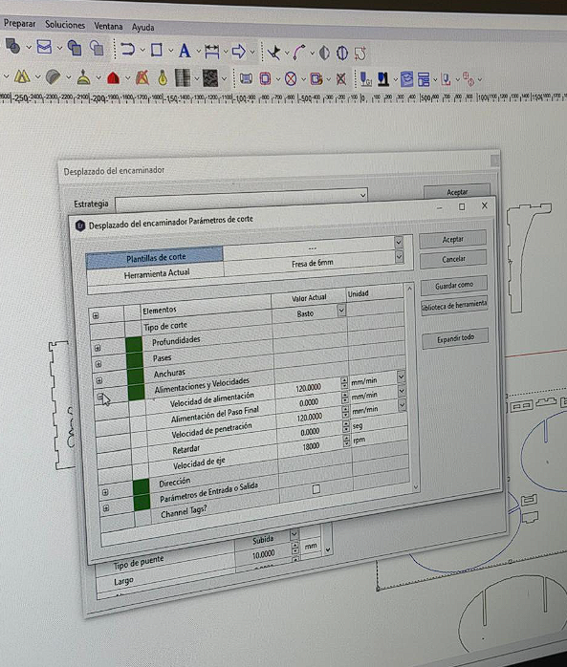
Img 15 — enRoute CAM — cutting parameters dialogenRoute "Desplazado del encaminador" (Router Offset) dialog with the Parámetros de corte panel open. Tool: Fresa 6mm. Feed rate (Alimentación y Velocidades): 120.000 mm/min. Final pass feed: 120.000 mm/min. Spindle speed (Velocidad de eje): 18,000 RPM. Bridge height (Subida): 10.000 mm. These are the exact parameters used for all machining runs on the MultiCam 3000.
Test Results
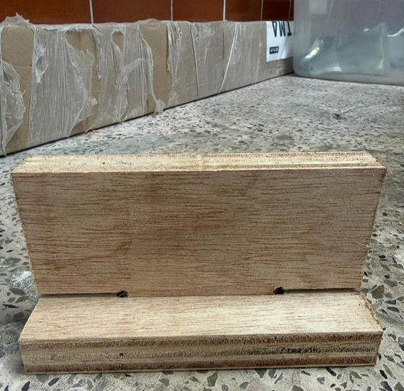
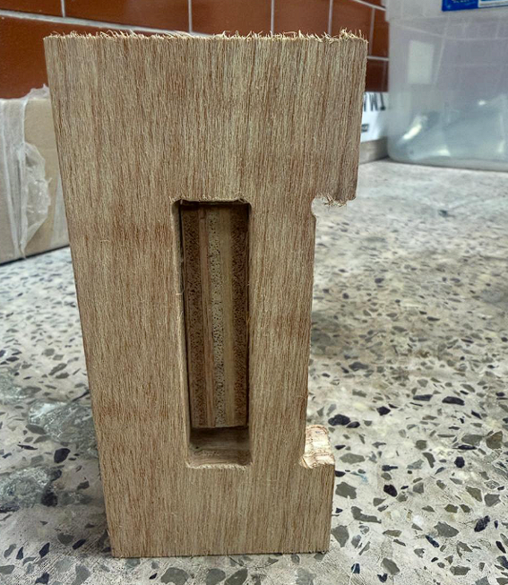
Img 16 — Press-fit joint assembled — side viewFinal assembled press-fit joint showing the vertical panel seated cleanly into the horizontal base slot. The joint holds by friction alone — no glue or fasteners. Clean cut edges visible on both pieces confirm correct tool depth and feed rate settings.Img 17 — Machined piece — slot with corner relief visibleFront view of a machined plywood test piece showing the full slot opening with corner relief clearly visible at both ends. The slot walls are clean and the corner radius left by the 6 mm tool is evident — this is exactly the geometry that requires dog-bone or semi dog-bone relief to allow square mating parts to fully seat.
Observation
Semi Dog-Bone — Fit Requires Slight Force
In the Semi Dog-Bone test, the joint fit but required some force to assemble — indicating the relief circle was slightly small for the actual machined radius. This means exact measurement of tool diameter and material thickness is critical for a perfect fit. Even small deviations accumulate across a joint.
Winner: Semi Dog-Bone
As demonstrated by the test results, the Semi Dog-Bone produced the best outcome across all three strategies. The relief is far less visually noticeable, the circular cutout blends more naturally into the geometry, and it maintains sufficient clearance for proper assembly — making it the ideal choice for furniture and visible structural components.
Advantages of Semi Dog-Bone
◑
Best aesthetic finish
The relief is far less visually noticeable compared to standard Dog-Bone, where the full circle is visible from the front face.
⊙
Natural blending
The circular cutout blends more naturally into the geometry — it does not interrupt the line of the slot as aggressively as the other strategies.
⊞
Sufficient clearance
Maintains enough clearance for proper assembly while removing less material than a full Dog-Bone relief.
⌂
Ideal for furniture
Best suited for furniture and visible components where joint appearance matters as much as structural performance.
Individual Reflections
What each team member learned from this week's assignment.
Nicolas
Working on the corner relief strategies made me realize that CNC machining forces you to design with the tool in mind — not just the final geometry. A perfectly square pocket in CAD becomes a rounded pocket on the machine, and that gap between intention and reality has to be resolved through design decisions rather than post-processing. Modeling all three strategies parametrically in Fusion 360 also showed me how much time parametric constraints save: changing the tool diameter updated every relief circle instantly. The Semi Dog-Bone result confirmed that the best engineering solution is often the one that balances function and appearance rather than maximizing one at the expense of the other.
Micaela
The press-fit tolerance test was the most instructive part of this week for me. Starting at 18.0 mm and stepping up in 0.1 mm increments made it clear that what feels like a small number on paper produces a very noticeable difference in assembly feel. The tabs test also changed how I think about CNC toolpaths — I had not considered that a fully cut contour leaves the part free to move and potentially collide with the tool. Understanding why tabs exist, and seeing them in the machined piece, made the whole fixturing concept much more concrete than any diagram would have.