Development Boards & Microcontrollers

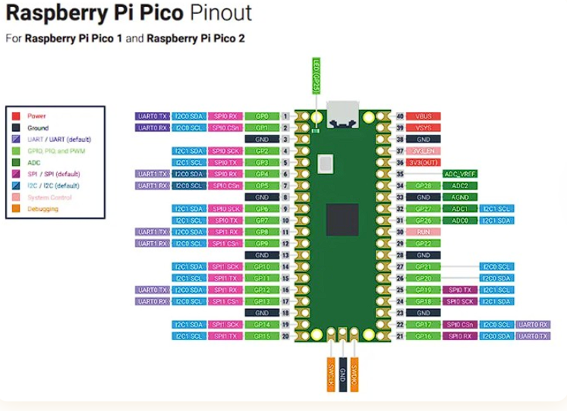
Since it was our first time reading a microcontroller datasheet, our instructor gave us a quick explanation using the pin diagram (pinout) of the Raspberry Pi Pico 2 W as an example. From that, we learned how to interpret what each label means, how to identify the function of each pin, and how to read this type of schematic.
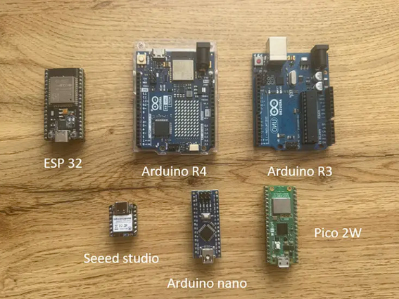
All development boards together
All boards reviewed this weekLeft to right: ESP32, Arduino R4, Arduino R3 (top row) — Seeed Studio XIAO, Arduino Nano, Pico 2W (bottom row).

What is a Development Board?

A development board is a complete electronic platform designed to help prototype, test, and program embedded systems easily. It includes a microcontroller as its main brain, along with voltage regulators, USB interface, communication ports, buttons, LEDs, and sometimes wireless modules.

What is a Microcontroller?

A microcontroller is a small integrated circuit that acts as the brain of an embedded system. It contains a processor (CPU), memory, input/output pins, and communication interfaces all inside a single chip.
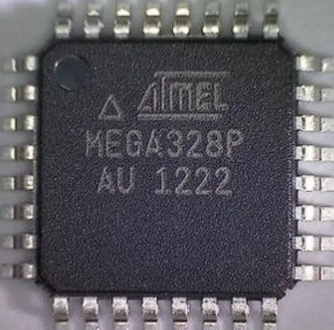
ATmega328P microcontroller chip
ATmega328P — bare microcontroller chipThe actual IC that powers both the Arduino UNO R3 and Nano. An Atmel (now Microchip) 8-bit AVR chip in TQFP package.
Fab Academy ULima — explore the full group assignment documentation on the official page:
fabacademy.org/2026/labs/ulima/ ↗
01

Raspberry Pi Pico 2 W

ARM Cortex-M33 · RP2350 · dual-core
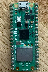
Raspberry Pi Pico 2W board
Raspberry Pi Pico 2W — boardGreen PCB with RP2350 chip, USB-C, BOOTSEL button, and onboard WiFi/BT module.
Raspberry Pi Pico pinout
Raspberry Pi Pico pinout diagramColor-coded pin reference for Pico 1 and Pico 2. Shows GPIO, ADC, I2C, SPI, UART, power, and debug pins.

The Raspberry Pi Pico 2 W is a development board with integrated WiFi, which allows it to be used in IoT projects. The board operates at 3.3V and supports SPI, I2C, and UART communication protocols.

MCU — RP2350
ArchitectureARM Cortex-M33 (dual-core)
FrequencyUp to 150 MHz
SRAM520 kB
FlashExternal (~4 MB)
ADC12-bit
PWM16 channels
PIO blocks2 programmable I/O
Total Pins40 (up to 30 GPIO)
Wireless — CYW43439
WiFi802.11 b/g/n (2.4 GHz)
BluetoothBLE 5.2
Operating Voltage3.3V
I2C / SPI / UART2 / 2 / 2 buses

Workflow Chain

  • 01
    Write code

    In C/C++ (official SDK) or MicroPython from VS Code or Thonny.

  • 02
    Compile

    ARM GCC compiler translates the code into RP2350 instructions.

  • 03
    Generate binary

    A .uf2 file ready to upload is produced.

  • 04
    Flash

    Press BOOTSEL + USB — Pico appears as a storage drive, drag the .uf2.

  • 05
    Execute

    The board restarts automatically and runs the program.

  • 06
    Monitor

    View results via VS Code or Thonny serial monitor.

Toolchain

ToolPurpose
Pico SDKOfficial library to access RP2350 pins and functions
ARM GCCCompiles code for the Cortex-M33 processor
CMake + MakeOrganizes and builds the project
UF2 FormatFirmware file loaded via USB without extra hardware
VS Code + Pico Ext.Recommended IDE; configures and compiles with one click
ThonnyMicroPython IDE; simpler and more direct
OpenOCD / SWDAdvanced debugging using a second Pico as debugger

02

Arduino UNO R4 WiFi

ARM Cortex-M4 · R7FA4M1AB3CFM
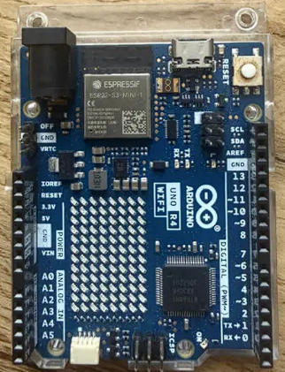
Arduino UNO R4 WiFi board
Arduino UNO R4 WiFi — boardFeatures the ESP32-S3-MINI-1 module (top left) alongside the R7FA4M1 main MCU and the iconic LED matrix.
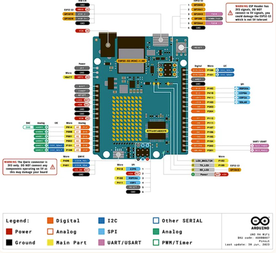
Arduino UNO R4 WiFi pinout
Arduino UNO R4 WiFi pinoutFull pin reference showing digital, analog, I2C, SPI, UART, DAC, and ESP32-S3 header pins with color-coded legend.

The Arduino UNO R4 WiFi is an upgraded version of the classic UNO platform designed for embedded programming, rapid prototyping, and IoT applications. It integrates a powerful 32-bit microcontroller and a WiFi/Bluetooth module.

MCU — R7FA4M1AB3CFM
Architecture32-bit ARM Cortex-M4
Flash256 kB
SRAM32 kB
Data Flash8 kB (EEPROM)
ADC14-bit
DACUp to 12-bit
CAN busYes
DMAC4 channels
Wireless — ESP32-S3-MINI-1
WiFi2.4 GHz 802.11 b/g/n
BluetoothBLE 5
SRAM512 kB
ROM384 kB
Voltage3.3V (logic translator)

Workflow Chain

  • 01
    Write code

    In C/C++ from the Arduino IDE (called a "sketch").

  • 02
    Compile

    Arduino IDE uses ARM GCC to translate code for the Cortex-M4.

  • 03
    Generate binary

    A .hex or .bin file ready to upload is produced.

  • 04
    Flash

    Loaded directly via USB with one click from the IDE.

  • 05
    Execute

    The board restarts automatically and runs the program.

  • 06
    Monitor

    Results visible in the Arduino IDE Serial Monitor.

Toolchain

ToolPurpose
Arduino IDEMain environment: editor, compiler, and uploader in one
ARM GCCCompiles C/C++ code for the Cortex-M4 processor
Arduino Core (Renesas)Official libraries and drivers for all pins and modules
USB BootloaderLoads programs directly via USB without extra hardware
WiFiS3 LibraryOfficial library to control the ESP32-S3 module from code
VS Code + PlatformIOAdvanced alternative with more control over compilation

03

Arduino UNO R3

8-bit AVR · ATmega328P
Arduino UNO R3 board
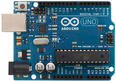
Arduino UNO R3 — boardClassic blue PCB with ATmega328P DIP package, USB Type-B connector, and standard Arduino shield headers.
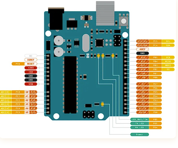
Arduino UNO R3 pinout
Arduino UNO R3 pinoutFull pin reference — digital, analog, SPI, I2C, UART, power, and built-in LED pins labeled with port names.

The Arduino UNO R3 is one of the most popular development boards for learning embedded systems. It is widely used in education and beginner projects to control LEDs, sensors, motors, and other electronic components.

MCU — ATmega328P
Architecture8-bit AVR
Frequency16 MHz
Flash32 kB
SRAM2 kB
EEPROM1 kB
ADC10-bit
Digital Pins14
Analog Inputs6
PWM6 channels

Workflow Chain

  • 01
    Write code

    In C/C++ from the Arduino IDE (called a "sketch").

  • 02
    Compile

    AVR-GCC translates code to instructions for the 8-bit ATmega328P.

  • 03
    Generate binary

    A .hex file ready to upload is produced.

  • 04
    Flash

    AVRDUDE communicates with the bootloader via USB and writes the .hex to Flash.

  • 05
    Execute

    The board restarts automatically and runs the program.

  • 06
    Monitor

    Results visible in the Arduino IDE Serial Monitor.

Toolchain

ToolPurpose
Arduino IDEMain environment: editor, compiler, and uploader in one
AVR-GCCCompiles C/C++ code for the 8-bit AVR architecture
AVRDUDETransfers the .hex to the chip via USB and bootloader
Bootloader (pre-flashed)Allows loading programs via USB without external hardware
Arduino Core LibrariesLibraries for pins, ADC, timers, and UART
Serial MonitorDisplays program results in real time

04

Seeeduino XIAO nRF52840

ARM Cortex-M4F · nRF52840
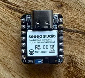
XIAO nRF52840 board
Seeed Studio XIAO nRF52840 — boardTiny form factor with USB-C, onboard BLE antenna, and RST button. Fits directly on a breadboard.
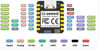
XIAO nRF52840 pinout
XIAO nRF52840 pinoutPin reference showing digital, analog, I2C, SPI, UART, power, and GND — color coded by function type.

The Seeeduino XIAO nRF52840 is a compact and powerful development board designed for IoT and Bluetooth applications. Despite its small size, it integrates wireless communication and advanced low-power features — ideal for wearables and battery-powered devices.

MCU — nRF52840
Architecture32-bit ARM Cortex-M4F
Flash1 MB
RAM256 kB
ADC12-bit
BluetoothBLE 5.0
USBFull-speed USB 2.0
Digital PinsUp to 14

Workflow Chain

  • 01
    Write code

    In C/C++ (Arduino IDE with Seeed nRF52 package), MicroPython, or CircuitPython.

  • 02
    Compile

    ARM GCC translates code for the Cortex-M4F at 64 MHz.

  • 03
    Generate binary

    A .hex or .uf2 file ready to upload is produced.

  • 04
    Flash

    Loaded via USB-C bootloader. Double-click reset activates storage mode if unresponsive.

  • 05
    Execute

    The board restarts automatically and runs the program.

  • 06
    Monitor

    Results visible in the Arduino IDE Serial Monitor.

Toolchain

ToolPurpose
Arduino IDEMain environment: editor, compiler, and uploader
ARM GCCCompiles C/C++ code for the Cortex-M4F at 64 MHz
Seeed nRF52 BoardsOfficial library for BLE and low-power functions
Seeed nRF52 mbedLibrary for TinyML and advanced sensors
UF2 BootloaderLoads program via USB-C without external programmer
SWD + JLinkAdvanced on-chip debugging during execution

05

ESP32 (ESP32-WROOM)

Xtensa LX6 · dual-core · 240 MHz
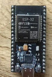
ESP32 DEVKIT board
ESP32 DEVKIT V4 — boardESP32-WROOM-32 module on a DevKit PCB. USB-C connector, EN and BOOT buttons visible at the bottom.
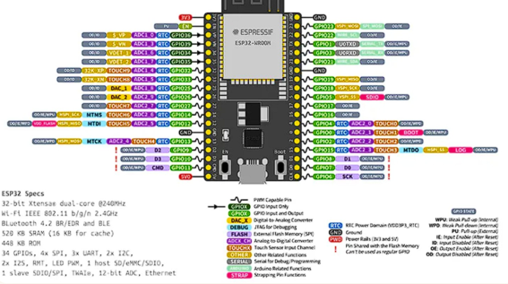
ESP32-WROOM pinout
ESP32-WROOM pinout diagramFull pin reference with GPIO, ADC, DAC, SPI, I2C, UART, touch, RTC, and PWM capabilities annotated.

The ESP32 development board is designed for IoT and wireless applications. It integrates a powerful dual-core processor and built-in WiFi and Bluetooth, widely used for smart devices, home automation, and wireless control systems.

MCU — Xtensa LX6
ArchitectureXtensa LX6 (dual-core)
FrequencyUp to 240 MHz
SRAM520 kB
FlashExternal (~4 MB)
ADC12-bit
DAC2× 8-bit
GPIOUp to 34 pins
SPI / I2C / UART4 / 2 / 3 buses
WiFi + BTIntegrated (classic + BLE)

Workflow Chain

  • 01
    Write code

    In C/C++ (Arduino IDE with ESP32 Core or ESP-IDF) or MicroPython.

  • 02
    Compile

    Xtensa GCC translates code for the dual-core Xtensa LX6 at 240 MHz.

  • 03
    Generate binary

    A .bin file ready to load into external Flash is produced.

  • 04
    Flash

    esptool.py transfers the binary via USB. May require pressing BOOT during upload.

  • 05
    Execute

    The board restarts automatically and runs the program.

  • 06
    Monitor

    Results visible in the Arduino IDE or ESP-IDF Serial Monitor.

Toolchain

ToolPurpose
Arduino IDE + ESP32 CoreAccessible environment with WiFi, BT, and dual-core support
Xtensa GCCCompiles C/C++ for the dual-core Xtensa LX6 at 240 MHz
esptool.pyOfficial Espressif tool to load firmware via USB
ESP-IDFProfessional framework with full chip access and FreeRTOS
FreeRTOSIntegrated real-time OS; tasks can run on both cores simultaneously
VS Code + PlatformIOAdvanced alternative compatible with Arduino and ESP-IDF

06

Arduino Nano

8-bit AVR · ATmega328P · compact
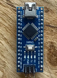
Arduino Nano board
Arduino Nano — boardCompact blue PCB with ATmega328P, Mini-USB connector, and breadboard-friendly pin layout.
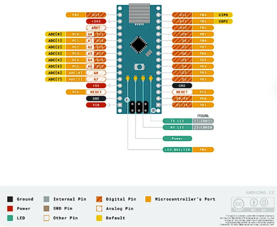
Arduino Nano pinout
Arduino Nano pinoutFull pin reference — digital, analog (8 inputs vs 6 on UNO), SPI, I2C, UART, power, and LED pins labeled.

The Arduino Nano offers similar functionality to the UNO but in a much smaller form factor. Although both boards share the same microcontroller, the Nano has 8 analog inputs (vs 6 on the UNO) and fits directly on a breadboard.

MCU — ATmega328P
Architecture8-bit AVR
Frequency16 MHz
Flash32 kB
SRAM2 kB
EEPROM1 kB
ADC10-bit
Digital Pins14
Analog Inputs8 (vs 6 on UNO)
USBMini / Micro USB

Uses the same workflow as the UNO R3 since it shares the ATmega328P microcontroller. Code is written in the Arduino IDE, AVR-GCC compiles it to a .hex file, and AVRDUDE loads it via USB through the bootloader.

07

Development Board Comparison

Side-by-side summary of all boards reviewed during the group assignment.

FeatureUNO R3NanoUNO R4 WiFiESP32Pico 2 WXIAO nRF52840
Main MCUATmega328PATmega328PR7FA4M1 (ARM M4)Xtensa LX6RP2350nRF52840
Architecture8-bit AVR8-bit AVR32-bit Cortex-M432-bit Xtensa (dual)32-bit Cortex-M33 (dual)32-bit Cortex-M4F
Clock Speed16 MHz16 MHz48 MHz240 MHz150 MHz64 MHz
Flash32 kB32 kB256 kB~4 MB~4 MB1 MB
SRAM2 kB2 kB32 kB520 kB520 kB256 kB
ADC10-bit10-bit14-bit12-bit12-bit12-bit
DACNoNo12-bit2× 8-bitNoNo
WiFiNoNoYesYesYesNo
BluetoothNoNoBLE 5Classic + BLEBLE 5.2BLE 5.0
Voltage5V5V5V3.3V3.3V3.3V
Low PowerNoNoNoDeep sleepDormant modeUltra low power
Price (approx.)~$5~$4~$27~$8~$7~$10
Best ForEducation basicsCompact projectsIoT intermediateIoT advancedIoT WiFi connectedWearables / BLE

Final Decision

Having reviewed all available microcontrollers, the choice was to work with the ESP32 DEVKIT V4 with the ESP-WROOM-32 processor, programmed using Thonny. Its dual-core architecture, integrated WiFi and Bluetooth, high speed (240 MHz), and generous memory make it the most versatile board for the type of projects planned.

Individual Reflections

What each team member learned from this week's assignment.

Nicolas

During the group assignment, I learned that reading a microcontroller datasheet is essential to understand the real capabilities and limitations of each board. I understood how factors such as architecture, clock frequency, memory, voltage logic, and communication protocols influence board selection for different embedded applications. This process also helped me distinguish between a development board and the microcontroller it contains, and improved my ability to compare platforms using technical information in a more objective and engineering-based way.

Micaela

This week I learned how to read and interpret a pinout diagram for the first time, which helped me understand what each pin does on a board before writing any code. Comparing the different toolchains made it clear how much the development experience varies between boards — from the simplicity of the Arduino IDE to the more flexible ESP-IDF. I also realized that board selection is not just about specs, but about which workflow best fits the project's needs.