Lab Safety Training
Before operating the laser cutter, we completed the lab's safety training. This covered proper equipment handling, emergency procedures, ventilation requirements, and material restrictions. Understanding safety protocols is essential before touching any machine.
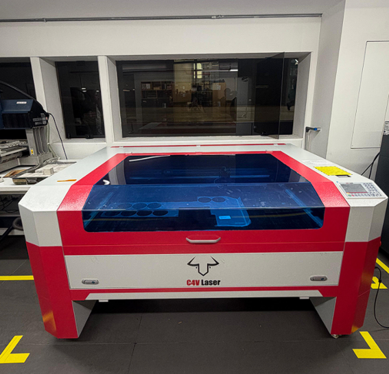
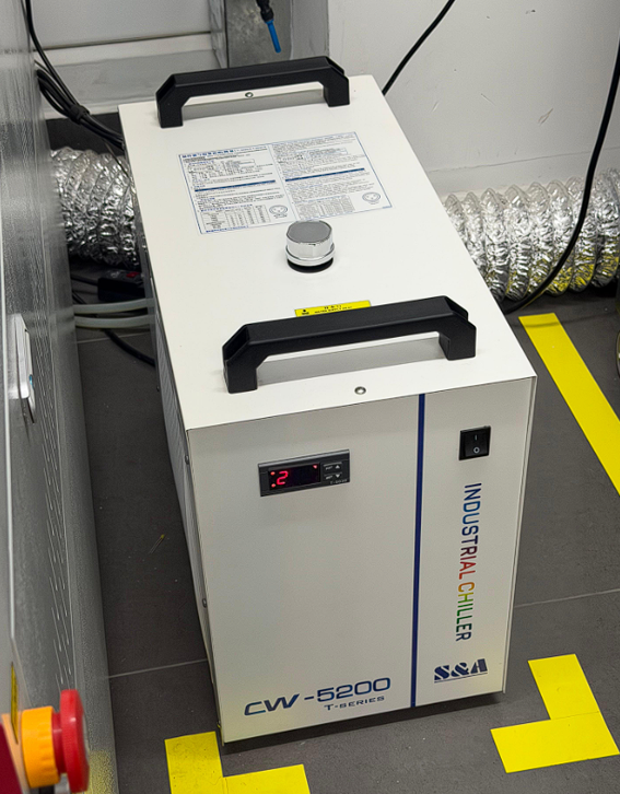
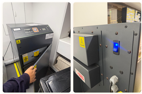
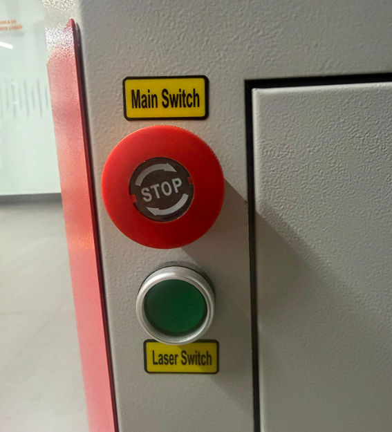
Key safety points covered:
- Never leave the machine unattended while cutting.
- Ensure ventilation and exhaust systems are active before starting.
- Do not cut PVC or materials that release toxic fumes.
- Keep a fire extinguisher accessible at all times.
- Always verify focus and material placement before running a job.
Laser Cutting Parameters
We explored the main parameters that affect the laser cutting process and how each variable directly influences the final result.
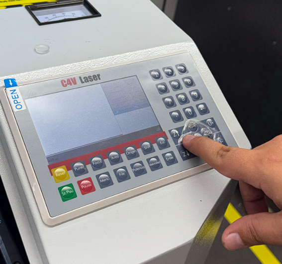
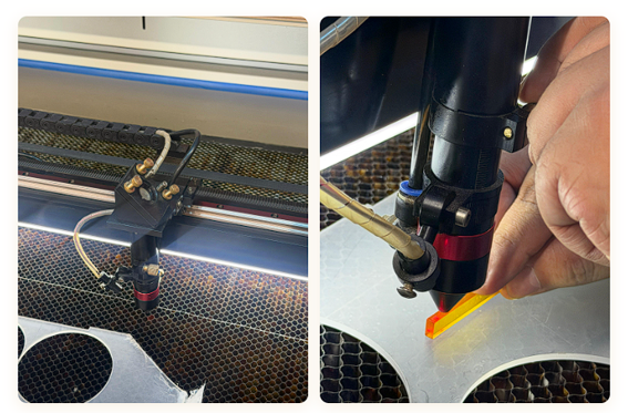
Focus
Distance between lens and material. Correct focus = clean precise cuts.
Power
Energy delivered (12–100%). Higher power cuts deeper but risks burning.
Speed
Head movement speed (1–100%). Lower = more heat. Higher = less penetration.
Rate (PPI)
Pulses per second. Higher rate = smoother edges on curves.
Kerf
Material vaporized during cutting. Must be measured per setup.
Joint Clearance
Intentional gap between parts. Compensates for kerf and tolerances.
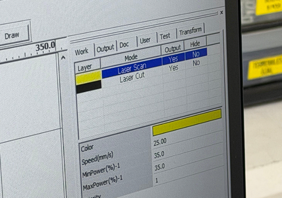
Types of Laser Operation
Cutting
Fully penetrates the material. High power, low speed.
Engraving
Removes surface material without cutting through. Lower power or higher speed.
Marking / Scoring
Very light surface treatment — fold lines, alignment guides.
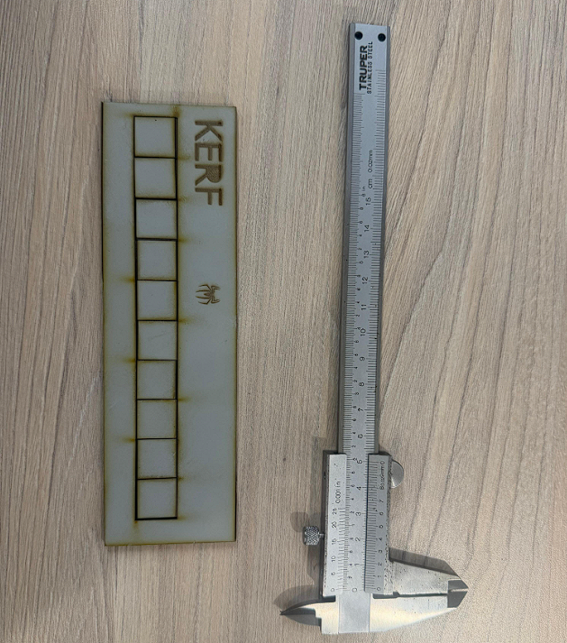
Kerf Measurement
We laser-cut multiple 20 mm squares, measured the total gap between them, and calculated an average value for accuracy.
Joint Clearance Test
- Too tight: no friction — pieces fall apart.
- Too loose: difficult or impossible to assemble.
- Correct clearance: controlled friction, holds firmly.
Laser Engraving Test
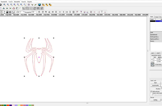
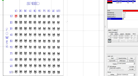
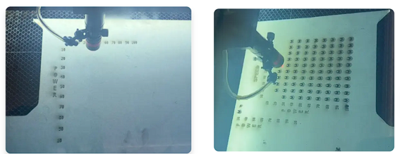
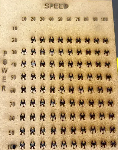
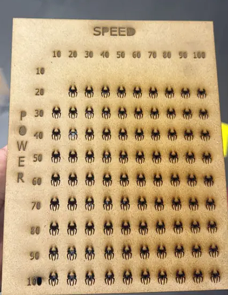
We prepared an engraving test file with a spider logo arranged in a 10×10 grid — each row = Power level, each column = Speed level. Different colors were assigned so each combination runs at its own settings in a single job.
| Result | Power level | Speed level | Engraving quality |
|---|---|---|---|
| Invisible | Below minimum | High | No visible engraving produced |
| Light | Low–mid | High | Faint mark, reduced intensity |
| Medium | Mid | Mid | Clear engraving, balanced result |
| Dark | High | Low | Deep, dark engraving mark |
Living Hinge Pattern
We designed a laser-cut pattern that allows MDF to become flexible — a living hinge. We also helped determine the kerf value using the square-gap measurement method.
Our initial goal was to create an MDF book that could open and close using a living hinge pattern. Even though the full-scale version did not work as expected, the experience gave us the foundation to redesign at a smaller, more refined scale.
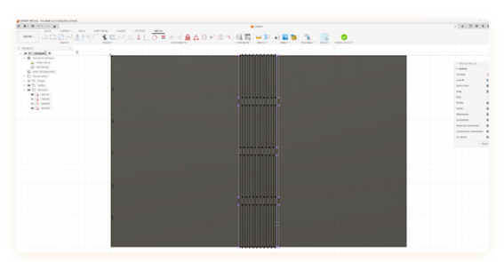
The design was built in Fusion 360 following the tutorial "Mastering Living Hinges for Laser Cutting", using a structured parametric workflow.
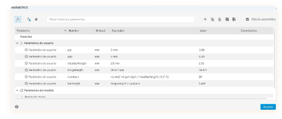
ply = 3 mm, gap = 6 mm, idealbarheight = 1.5 mm. Changing any value updates the entire model automatically.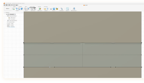
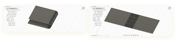
- 01
Sketch constraints
Applied Coincident, Horizontal/Vertical, Parallel, Equal, and dimensional constraints to fully define the hinge geometry.
- 02
Rectangular pattern tool
Replicated a single cut line evenly across the surface for uniform spacing across the entire hinge area.
- 03
Parametric gap control
Created
gap = 6 mmvia Modify → Change Parameters. Spacing directly affects flexibility. - 04
Project tool for alignment
Used the Project tool to reference edges into the sketch and keep the hinge pattern aligned to the part geometry.
- 05
Sheet metal simulation
Explored Fold and Refold tools to simulate bending and verify hinge behavior before cutting.
- 06
Export and geometry cleanup
Cleaned geometry in Rhino and AutoCAD before final cutting to remove internal lines interpreted as cut paths.
Other Lab Machines
During the safety training tour we documented the other cutting and fabrication equipment available in the Fablab.
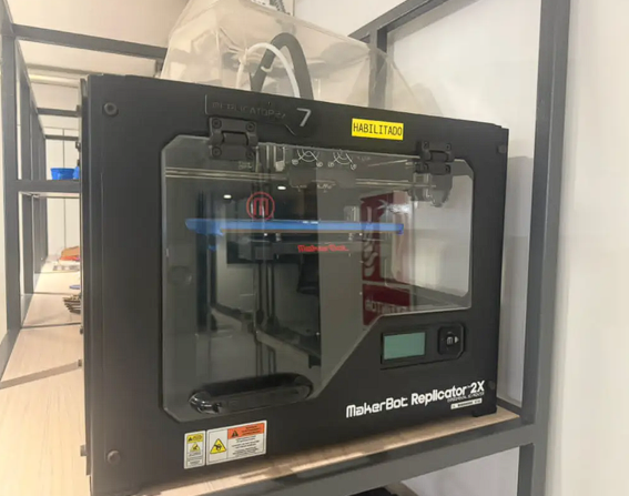
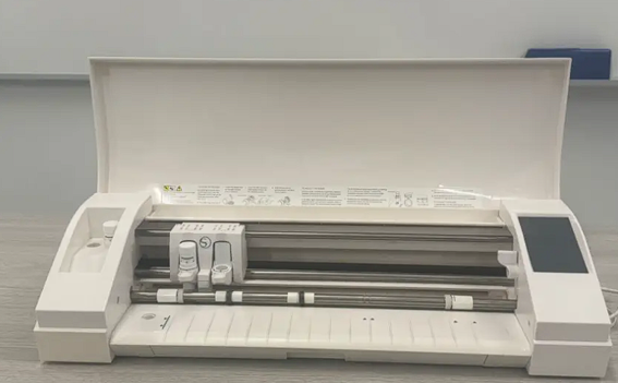
Individual Reflections
What each team member learned from this week's assignment.
This week gave me a hands-on understanding of how laser parameters interact. Measuring kerf showed me that even 0.05 mm matters for precision assemblies. Working with Fusion 360's parametric tools changed how I think about design: instead of fixed dimensions, I now think in variables. The living hinge experiment also taught me that a failed result is still a result — understanding why it didn't work was just as valuable.
The safety training was a good reminder that knowing your equipment is the first step to working well with it. Testing engraving parameters across a grid made the relationship between power and speed very tangible — seeing the difference between a nearly invisible mark and a deep dark engraving on the same piece made the theory click. I also learned to think about color-coded layers in laser software as a practical workflow tool, not just an organizational choice.
Files
© Fablab Ulima 2025 | Design: Tooplate