Individual Contributions

πŸ‘¨β€πŸ’» AndrΓ©s Mamani - CAD & Electronics Lead

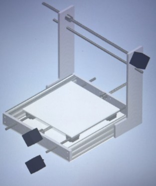
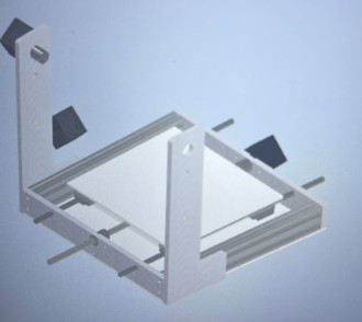
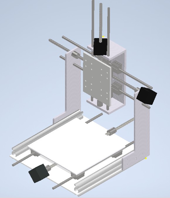
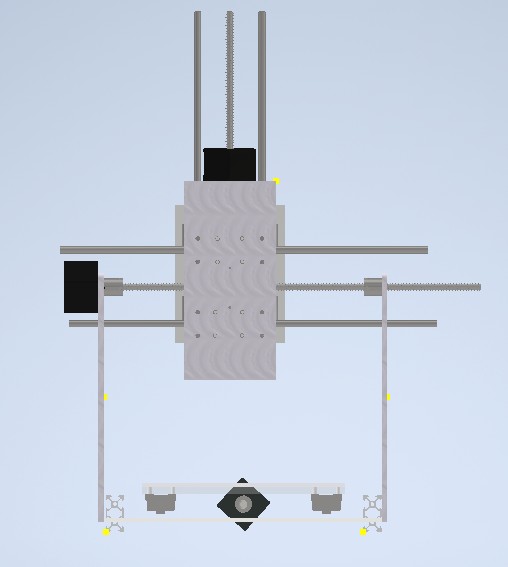
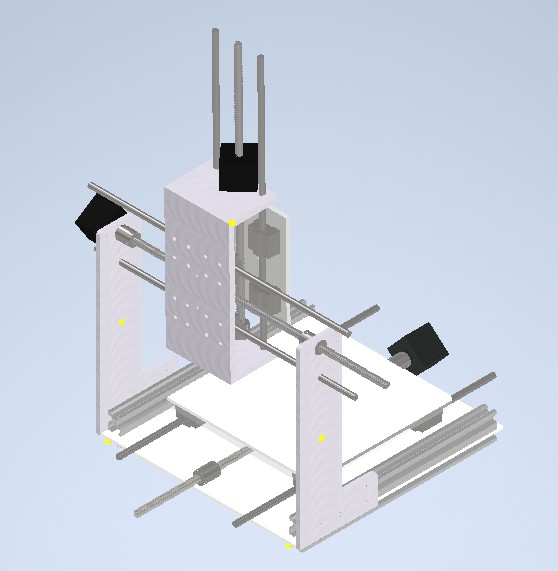
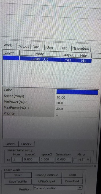
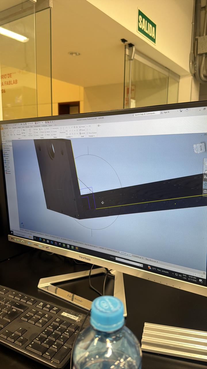
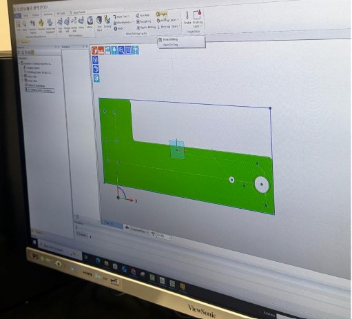
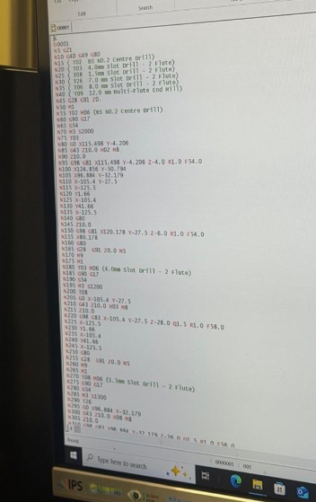
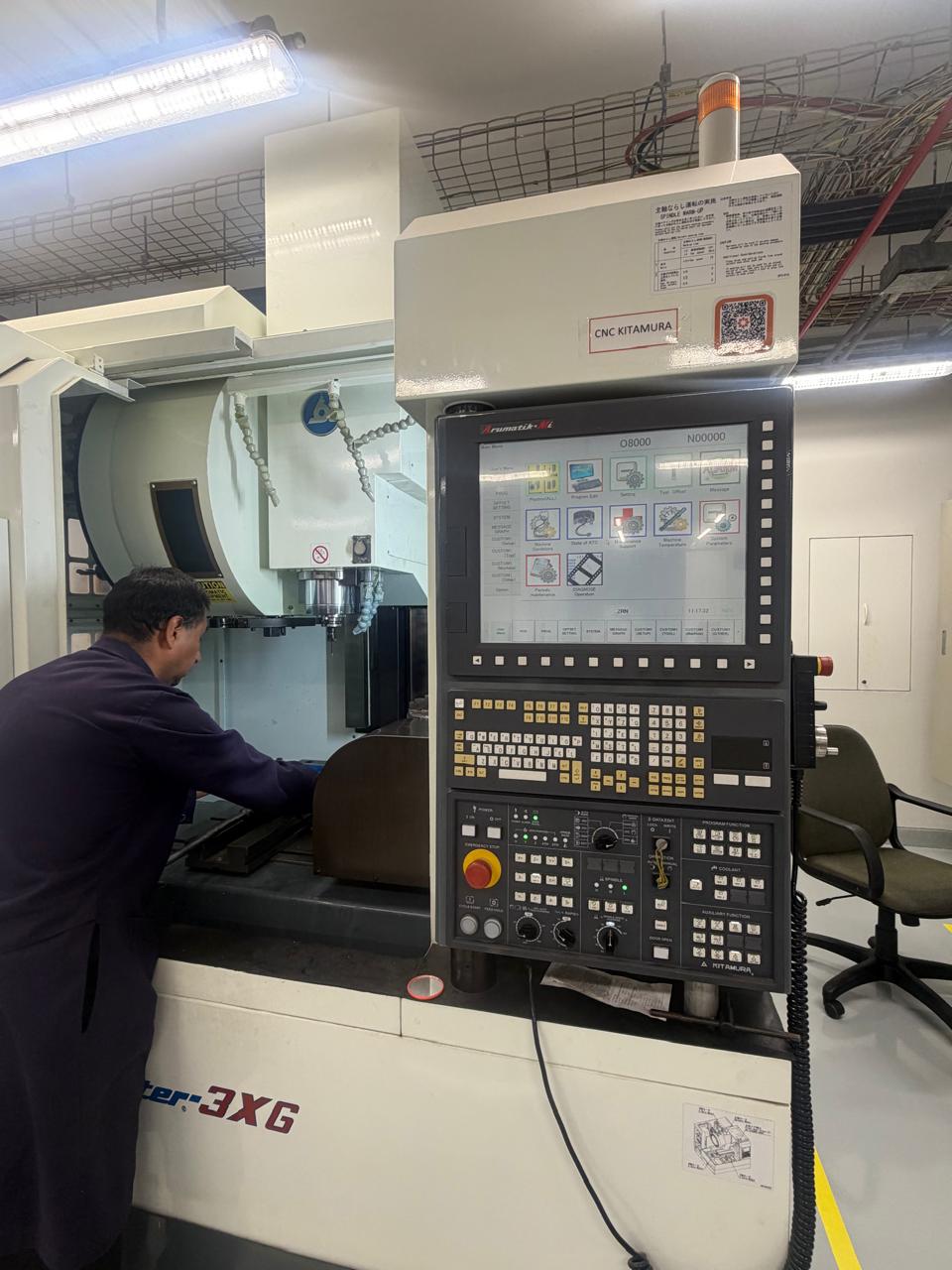
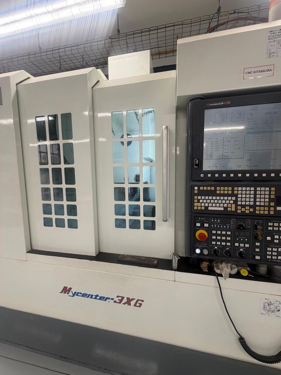
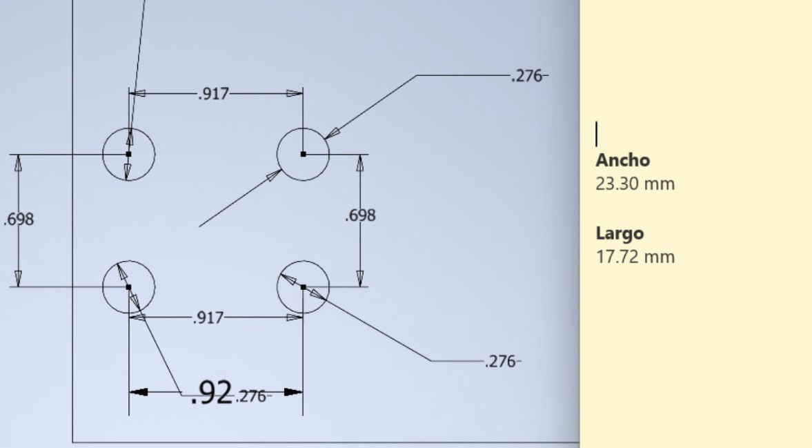
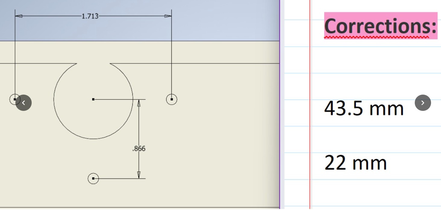
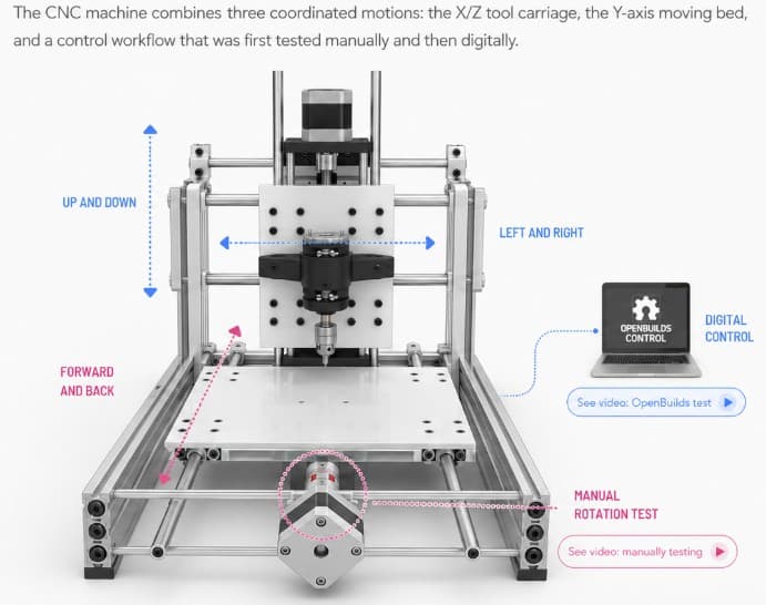
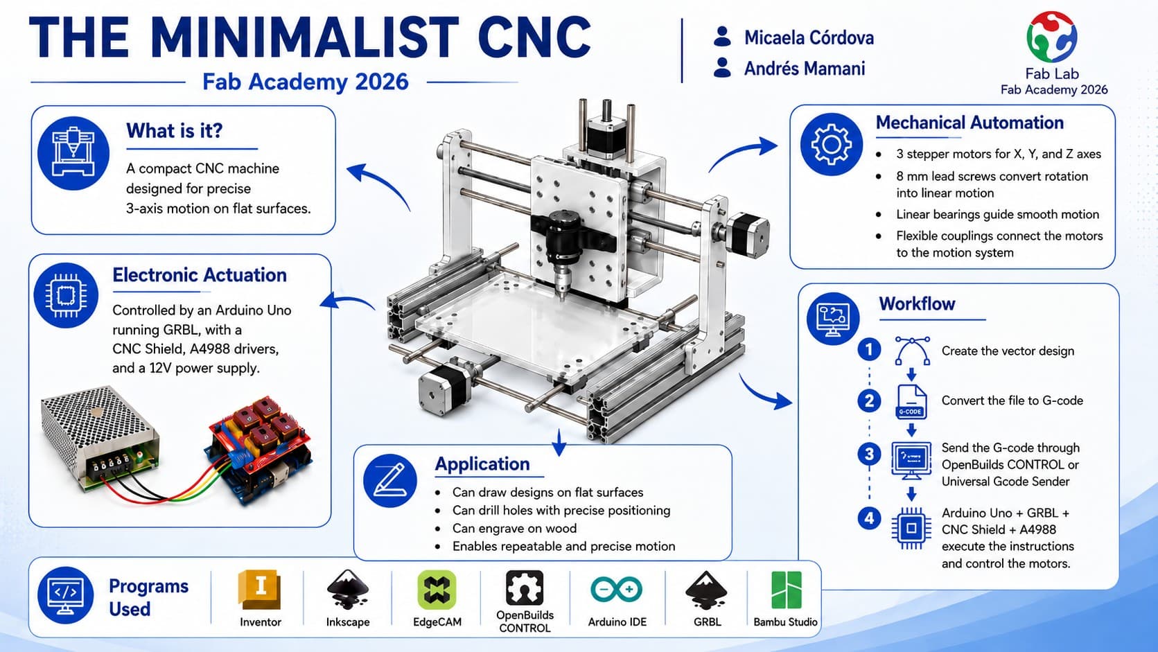
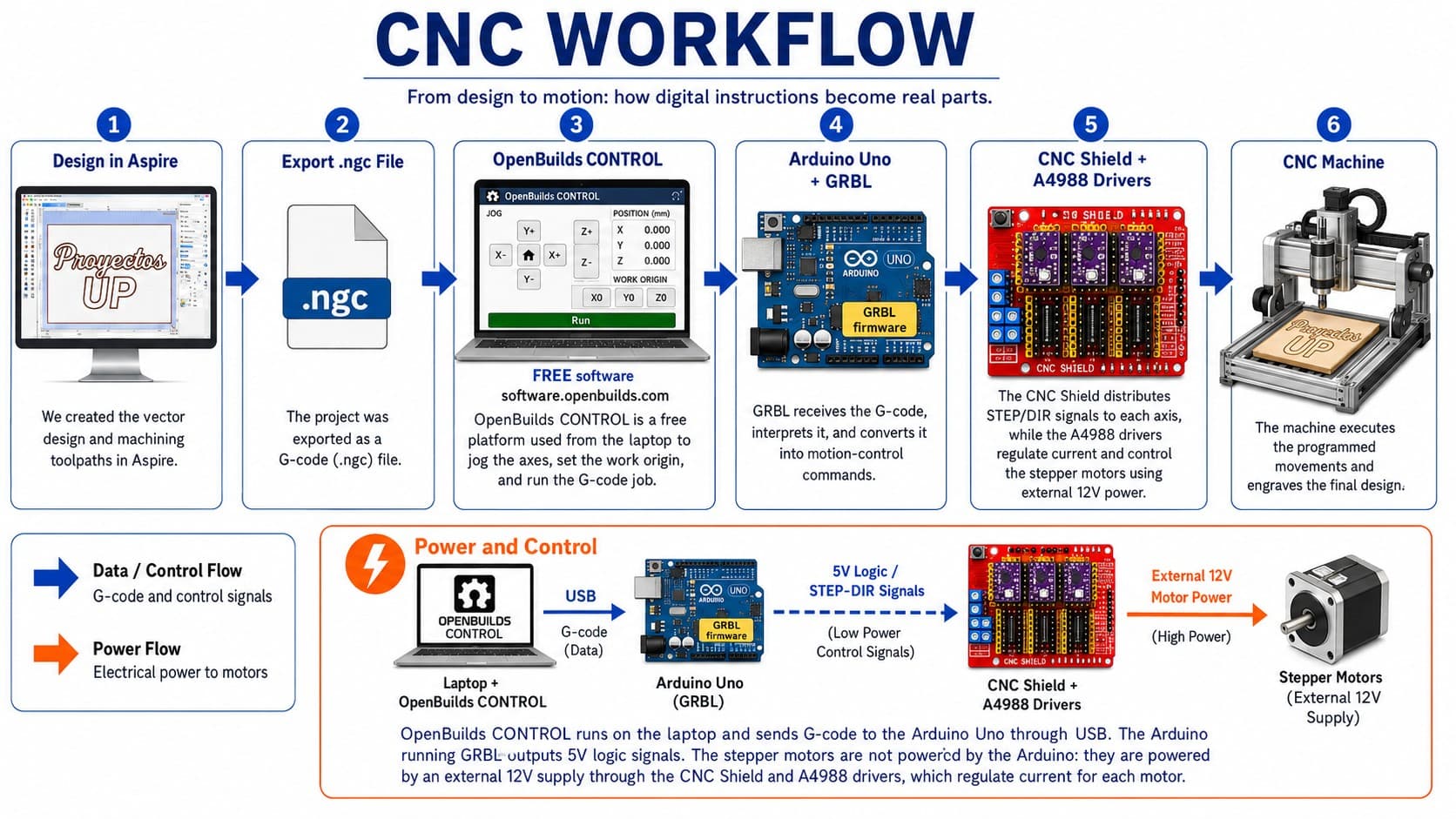
I contributed to the 3D modeling of the CNC machine in Autodesk Inventor and prepared all technical drawings. I supported the assembly process and contributed to the development of the control code using GRBL firmware. I also guided key decisions based on experience with the tools, materials, and machines used in the fabrication lab. My focus was on translating the design concept into precise digital models and ensuring electronic control systems worked seamlessly with the mechanical structure.

πŸ‘©β€πŸ”§ Micaela CΓ³rdova - Manufacturing & Documentation Lead

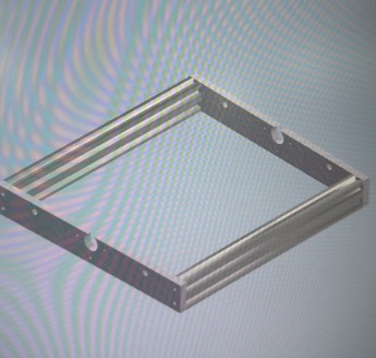
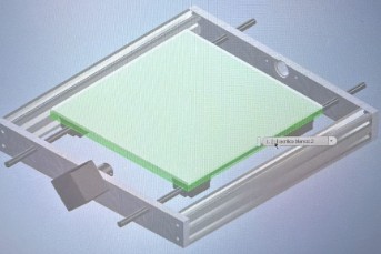
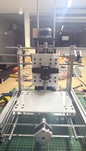
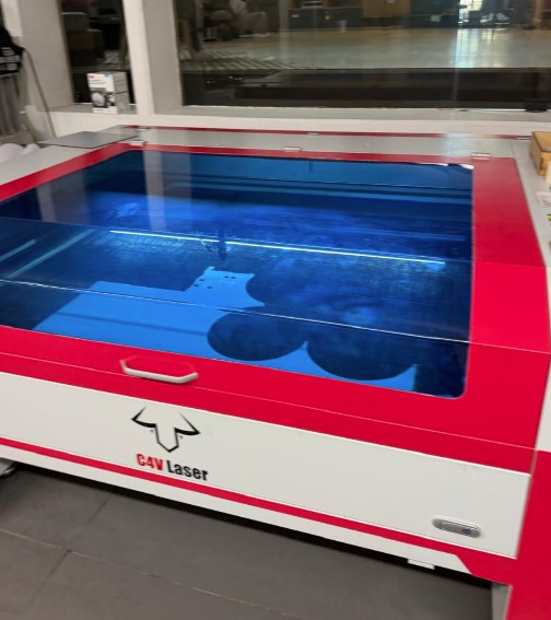
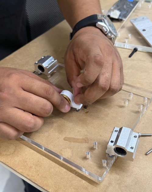
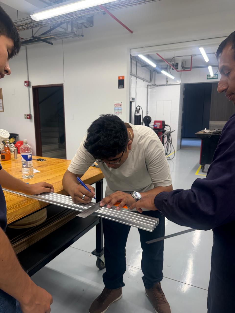
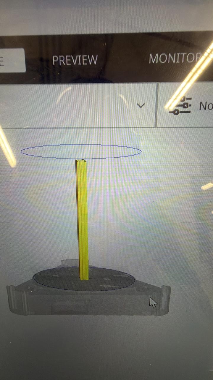
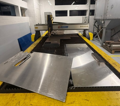
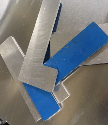
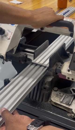
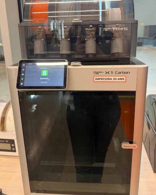
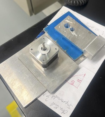
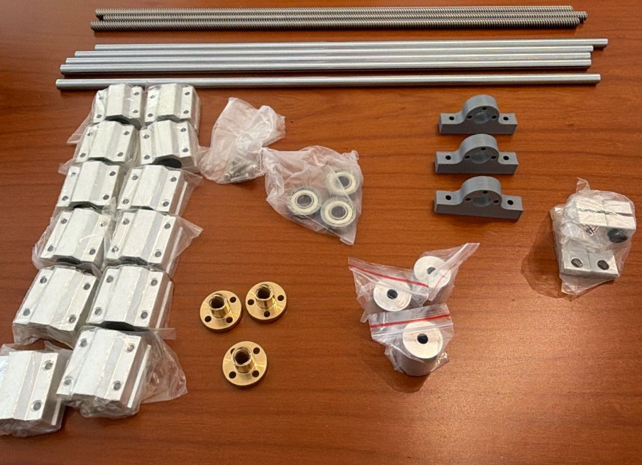
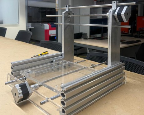
I contributed to the design of the parts and continuously adapted the models based on real component measurements. I supported the entire manufacturing and assembly process, especially in the fabrication of metal components and laser-cut acrylic parts. I performed extensive physical testing, ensured proper fitting of all components, and debugged assembly issues. I also prepared all presentation materials, including slides, videos, and comprehensive documentation. My focus was on bridging the gap between digital design and physical reality.

Team photo

Project Timeline & Schedule

This Gantt chart shows the week-long timeline of our CNC machine project, from initial research through final testing and documentation.

Monday
Tuesday
Wednesday
Thursday
Friday
πŸ“– Research & Inspiration
100%
✏️ Initial Sketch & Concept
100%
πŸ”§ CAD Modeling Phase 1
100%
πŸ”§ CAD Modeling Phase 2
100%
πŸ’Ύ DXF Export & CAM Prep
100%
πŸ”¨ Metal Cutting (CNC)
100%
⚑ Plasma Drilling
100%
βœ‚οΈ Laser Cutting (Acrylic)
100%
πŸ”© Assembly & Alignment
100%
βœ… Manual Testing
100%
πŸ’» Digital Control Testing
100%
πŸ“Έ Documentation & Presentation
100%

Color Legend: Research CAD Work Fabrication Assembly & Testing Documentation

Task Distribution

AndrΓ©s Mamani - Lead Designer & Assembly

  • 3D Modeling in Inventor - Complete design of all CNC parts and structural components
  • Technical Drawings - Generation of 2D profiles and specifications for fabrication
  • DXF Export - Preparation of laser cutting files for acrylic components
  • Assembly Coordination - Leading the assembly process and problem-solving
  • Control Code Development - GRBL firmware configuration and testing
  • Digital Testing - OpenBuilds CONTROL setup and axis calibration

Micaela CΓ³rdova - Manufacturing & Documentation

  • Design Adaptation - Adjusting models based on real component measurements
  • Metal Fabrication Coordination - CNC metal cutting, plasma drilling, and metal work
  • Laser Cutting - Supervision of acrylic component fabrication
  • Component Assembly - Physical assembly and alignment of all parts
  • Testing & Quality Control - Verification of fit, alignment, and movement
  • Documentation & Presentation - Photos, videos, slides, and final documentation

Project Schedule

Week Timeline

  • Monday - Initial Research & Concept - YouTube research, inspiration gathering, first sketch design
  • Tuesday - CAD Modeling Phase 1 - Individual parts modeling in Inventor, initial assembly testing
  • Wednesday - CAD Modeling Phase 2 - Complete assembly, DXF exports, design refinement
  • Thursday - Metal Fabrication & Laser Cutting - CNC metal cutting, plasma drilling, acrylic laser cutting
  • Friday - Assembly & Testing - Physical assembly, manual testing, digital control testing, final adjustments

Project Idea & Inspiration

At the beginning of the week, we decided to develop a minimalist CNC machine because it combines mechanical design, electronics, software control, and digital fabrication in one integrated system.

Our main inspiration came from small desktop CNC machines and from a YouTube playlist by Prof. Garcia (CNC FΓ‘cil de hacer en Casa), where he explains the process of building a CNC machine step by step. These videos helped us understand the basic structure, the movement system, the assembly sequence, and the workflow from design to G-code execution.

Inspiration Sources

Inspiration reference 1 Inspiration reference 2

Based on this research, we adapted the idea to the materials and components available in our lab. We focused on creating a compact CNC machine capable of moving in the X, Y, and Z axes, using lead screws, linear bearings, stepper motors, an Arduino Uno with GRBL, and a CNC Shield with A4988 drivers. This planning stage helped us define the machine structure, select the required components, and organize the fabrication process before starting the assembly.

The Design

Initial Sketch and Concept

The first stage of the project was to design the main structure of the CNC machine in Autodesk Inventor. Before modeling the full machine, we started with an initial sketch to understand the general shape, the position of the axes, and the space that each component would need.

Initial sketch

Individual Parts Modeling

After defining the first idea, we created the main parts of the CNC machine in Inventor. Each component was modeled separately, including the base, the side supports, the moving bed, the motor supports, and the plates for the X, Y, and Z axes. This helped us understand the dimensions of each piece before assembling the complete machine.

Inventor model 1 Inventor model 2 Inventor model 3 Inventor model 4

Assembly and Visualization

Then, all the parts were placed into an Inventor assembly file. This allowed us to visualize the complete CNC structure and check how the mechanical elements would work together. Through the assembly, we could identify the position of the motors, lead screws, shafts, couplings, bearings, acrylic plates, and aluminum profiles.

Assembly 1 Assembly 2 Assembly 3 Assembly 4 Assembly 5

DXF Export for Fabrication

One advantage of using Inventor was that we could generate the 2D profiles needed for fabrication. From the 3D model, we selected the flat faces of the structural pieces and exported them as DXF files. These files were later used to laser cut the acrylic components.

Laser cutter machine Laser cutting results

From Virtual to Physical: Solving Real-World Problems

Described Problems and How the Team Solved Them

One of the most important lessons during the CNC machine project was learning that digital design and physical reality don't always align perfectly. This section documents the specific problems we encountered when transitioning from 3D virtual models to real fabricated components, and how we solved each issue.

πŸ”§ Problem 1: Motor Mounting Dimension Errors

The Problem: Our original Inventor model specified certain distances between mounting holes for the NEMA stepper motors. However, when we received the actual motors and tried to assemble them, the holes in our fabricated metal plates did not align with the motor's mounting holes.

Technical Details: The original design showed incorrect hole spacing. The actual motor had different mounting hole positions than what we calculated in CAD.

Motor mounting error diagram showing original dimensions

Original design showing measurement error in motor hole spacing - Ancho (Width) 23.30 mm, Largo (Length) 17.72 mm were incorrect

Solution: We redesigned the motor mounting plates with corrected dimensions to match the actual physical motors. This required re-cutting the front and back plates using transparent acrylic instead of the originally planned metal. The corrected dimensions ensure perfect alignment with the actual stepper motor specifications.

Corrected dimensions for motor mounting

Corrected design with accurate motor mounting dimensions - 43.5 mm and 22 mm spacing matches actual motor holes

πŸ”§ Problem 2: Coupling and Lead Screw Alignment

The Problem: The flexible couplings that connect the stepper motors to the lead screws require precise spacing and alignment. Our initial design did not account for the exact thickness and offset of the couplings, resulting in misalignment between the motor shaft and the lead screw.

Solution: We manually drilled and adjusted holes in several mounting plates to achieve proper alignment. The acrylic plates we switched to proved more flexible for iterative corrections compared to metal. We tested alignment repeatedly and made fine adjustments until the couplings rotated concentrically with the lead screws.

Acrylic components being tested and adjusted

Testing and adjusting cut acrylic components for proper alignment - hands-on validation of digital designs

πŸ”§ Problem 3: Bearing Support Positioning

The Problem: The linear ball bearings that guide the shafts require exact positioning to ensure smooth, straight movement. Our CAD model estimated these positions, but once we assembled the real components, some bearings were slightly misaligned, causing binding and resistance when moving the axes manually.

Solution: We used shims and spacers to adjust bearing positions. In some cases, we manually opened existing holes or adjusted mounting surfaces to achieve proper alignment. These physical corrections were documented and fed back into the digital model for future iterations.

πŸ“‹ Key Lessons from Virtual to Physical Transition

  • Always Measure Real Components First - Don't assume catalog dimensions are exact. Physical motors, couplings, and bearings can have manufacturing tolerances.
  • Prototype and Test Early - Test your design with actual components before mass-fabricating all parts.
  • Choose Flexible Materials - Acrylic proved superior to metal for rapid iteration because holes could be drilled or adjusted on-demand.
  • Document All Corrections - Keep records of what needed adjustment so the next iteration can be more accurate.
  • Continuous Model Updates - The digital model must reflect the physical assembly, not the other way around.
  • Tolerances Matter - Manufacturing tolerances (Β±0.5mm, Β±1mm) can accumulate across multiple parts and cause assembly problems.

βœ… Results of Our Corrections

After implementing these corrections, the machine achieved:

  • Smooth Axis Movement - All three axes (X, Y, Z) moved without binding or resistance
  • Proper Motor Mounting - Motors were firmly secured with correct alignment
  • Accurate Lead Screw Motion - Lead screws rotated concentrically with motor shafts
  • Improved Mechanical Precision - The machine was ready for successful digital control testing

Conclusion: The transition from virtual CAD design to physical fabrication revealed that engineering is as much art as it is science. Tolerances, real-world manufacturing variability, and the unpredictability of physical assembly require flexibility, iterative problem-solving, and a willingness to adapt the design based on physical reality. This experience reinforced the importance of prototyping, testing, and continuous feedback loops in the design-to-manufacturing process.

Mechanism

Mechanism diagram

Image created with ChatGPT

1. The X and Z Carriage

The central carriage holds the tool and controls the working movement. The X-axis moves the carriage from left to right, while the Z-axis moves the tool up and down to approach or separate from the work surface. This allows the machine to position the tool correctly before engraving, drawing, or cutting.

2. The Y-Axis Bed

The lower bed moves the material forward and backward. During the first assembly stages, we manually tested this axis by rotating the rods through the couplings installed in the acrylic bed. This helped us verify that the movement was smooth and aligned before powering the system.

3. Control and Motion Testing

After the manual verification, the machine was also controlled using OpenBuilds CONTROL. From the laptop, we were able to jog the axes, move the bed and the motorized system, and establish the work origin before running a G-code job. This allowed us to test the machine digitally and confirm that the mechanical and electronic systems were working together.

Main Components & Inventory

Complete inventory of components

Mechanical Components

  • 3 flexible shaft couplings, 8 mm – connect the stepper motor shafts to the lead screws and transmit rotational motion.
  • 3 lead screws, 8 mm diameter, approximately 40 cm long – convert the rotational movement of the motors into linear movement for the X, Y, and Z axes.
  • 3 lead screw nuts – move along the lead screws and transfer the motion to the moving parts of the machine.
  • 12 linear ball bearings, 8 mm – allow smooth and guided linear movement along the steel shafts.
  • 5 hardened steel shafts, 8 mm diameter, approximately 40 cm long – guide the movement of the carriage and bed.
  • 2 shaft supports, 8 mm – hold and align the guide shafts to keep the structure stable.
  • 3 standard bearings, 8 mm – support rotating parts and reduce friction.
  • Laser-cut acrylic plates – used for the machine bed, structural supports, and mounting surfaces.
  • Aluminum profiles – provide the main structural frame of the CNC machine.
  • 3D-printed support parts – used for specific holders and mechanical adaptations during the prototype stage.
  • Tool holder / spindle holder – holds the engraving, drawing, or cutting tool in place.
  • Fasteners, M3 screws, nuts, and spacers – used to assemble and secure all mechanical parts.
  • Threaded sleeves and mounting pieces – help fix components to the acrylic bed and maintain alignment.

Electronic Components

  • Arduino Uno running GRBL firmware – works as the main controller and interprets the G-code commands.
  • CNC Shield – connects to the Arduino Uno and distributes the STEP and DIR control signals to each motor driver.
  • 3 A4988 stepper motor drivers – control the current and movement of each stepper motor.
  • 3 stepper motors – generate the movement for the X, Y, and Z axes.
  • 12V external power supply – provides the power required by the stepper motors through the CNC Shield and drivers.
  • USB connection – connects the laptop to the Arduino Uno and sends the G-code commands from the control software.
  • Wires and connectors – used to connect the motors, drivers, shield, and power supply.

Software

  • Aspire – used to create the vector design, prepare the machining toolpaths, and export the G-code file.
  • OpenBuilds CONTROL – used to connect the laptop to the CNC machine, jog the axes, set the work origin, and run the G-code job.
  • GRBL – firmware installed on the Arduino Uno that converts G-code into motion-control commands for the CNC machine.
  • Inventor – used for the 3D modeling and mechanical design of the CNC structure and parts.

CNC Workflow

For this machine, we followed a digital workflow that connected the design process, G-code generation, machine control software, electronics, and the physical movement of the CNC machine. This workflow demonstrates how a digital design is transformed into a physical machined result.

Complete Workflow Process

Step-by-Step Explanation

1. Design in Aspire

First, we created the vector design in Aspire. The design used for this test was the text "UP". In Aspire, we prepared the drawing and generated the machining toolpaths according to the material and the type of operation we wanted to perform. After finishing the toolpath setup, the project was exported as a G-code file with the .ngc extension.

2. Loading G-code into OpenBuilds CONTROL

The .ngc file was then opened in OpenBuilds CONTROL, a free machine-control platform available at software.openbuilds.com. This software allowed us to connect the laptop to the CNC controller, load and execute the G-code file, manually move the machine axes, and set the work origin before starting the job. This was important because we needed to position the tool correctly and define the zero points for the X, Y, and Z axes.

3. G-code Transmission to Arduino

OpenBuilds CONTROL sent the G-code from the laptop to the Arduino Uno through a USB connection. The Arduino Uno was running GRBL firmware, which is designed to interpret G-code commands and convert them into motion-control instructions for CNC machines.

4. Signal Processing and Motor Control

The Arduino Uno does not directly power the motors. Instead, it sends low-power 5V logic signals, such as STEP and DIR signals. These signals indicate when each motor should move and in which direction. The Arduino was connected to a CNC Shield, which works as an interface between the Arduino and the motor drivers. The CNC Shield helps organize the connections for each axis and distributes the control signals to the corresponding stepper drivers.

5. Motor Driver and Power Supply

For motor control, we used A4988 stepper motor drivers. These drivers receive the 5V control signals from the Arduino and use an external 12V power supply to drive the stepper motors. This means that the Arduino is not converting 5V into 12V. Instead, the A4988 drivers use the 5V logic signals to switch and regulate the external 12V motor power. They also control the current delivered to each motor, allowing the CNC machine to move accurately step by step.

6. Physical Execution

Finally, the CNC machine executed the programmed movements and engraved the "UP" design onto the material. Through this workflow, a digital design was transformed into a physical machined result.

Workflow diagram

Mechanical Fabrication Process

After completing the 3D model, we started the mechanical fabrication process by checking the real components and preparing the materials for assembly. This process combined multiple manufacturing techniques including measurement, CAD verification, CAM preparation, CNC metal cutting, plasma drilling, and laser cutting.

Initial Inspection and Planning

At this stage, we compared the digital design with the physical parts, such as the aluminum profiles, motors, shafts, couplings, screws, and support pieces.

Measurement and Marking

First, we measured the aluminum profiles and marked the required dimensions. This step was important because the frame needed to match the dimensions of the Inventor model and support the movement system correctly.

Measurement and marking

CAD Verification and Design Review

Before machining the metal parts, we reviewed the design in Inventor and checked the geometry of the pieces that had to be manufactured. This helped us verify the shape, dimensions, and position of the holes before sending the parts to fabrication.

CAM Preparation for Metal Cutting

For the metal fabrication process, we used CAM (Computer-Aided Manufacturing) software to prepare the cutting paths. We tested and reviewed the geometry in programs such as EdgeCAM and Libellula before machining, which allowed us to check the toolpath and generate the necessary G-code instructions for the CNC metal-cutting machine.

CAM preparation on monitor CAM Libellula software design CAM software simulation

CNC Metal Cutting Machine - Laser Cutting Process

The first step of metal fabrication was to use a CNC metal cutting machine (Mitamura) that uses laser cutting technology combined with high-pressure water jet or plasma. This machine reads the G-code generated from our CAM software and creates precise cuts in metal plates.

Finished metal parts CNC control panel showing toolpath

Process Details:

  • G-code Generation - CAM software produces G-code file with cutting coordinates and feed rates
  • Machine Setup - Load metal sheet onto CNC cutting table with proper alignment
  • Toolpath Verification - Monitor preview on CNC control screen to confirm cutting pattern
  • Laser Cutting Execution - Machine cuts metal parts with high precision following CAM instructions
  • Quality Output - Clean cuts with minimal burrs, accurate dimensions matching CAD design
CNC cutting preview

Plasma Drilling Machine - Hole Creation

After the initial laser cuts, the metal parts needed precision holes for motor mounting, shaft supports, and fasteners. We used a plasma drilling machine (LAGUN) to create these holes with extreme precision.

Metal parts after cutting and processing

Plasma Drilling Process:

  • Plasma Technology - Uses high-temperature plasma jet to cut precise holes through metal
  • Accuracy - Maintains hole positions within millimeters to match motor and bearing specifications
  • Speed - Faster than conventional drilling, reduces production time significantly
  • Clean Holes - Produces smooth hole edges with minimal deformation
  • Multiple Holes - Can create complex hole patterns for mounting brackets and support structures

Metal Cutting with Saw - Structural Beams

For the structural aluminum and steel beams, we used a precision metal saw to cut them to exact lengths. This step required careful measurement and multiple pieces to be cut to the same dimension for frame consistency.

Metal parts after cutting and processing

Polishing with Metal Router Machine

After all cutting operations, we used a metal router machine to polish and finish the metal surfaces. This removed sharp edges, burrs, and improved the overall finish of the components, making them safe to handle and suitable for precision assembly.

LAGUN plasma drilling machine

Results

3D printed support parts

3D Printing for Rapid Prototyping and Support Parts

In addition to the metal parts, we fabricated support components using 3D printing. These pieces were useful for prototype adjustments, motor mounts, and specific mechanical adaptations during the prototype stage. 3D printing allowed us to quickly iterate on designs and test different configurations before committing to permanent metal solutions.

Overall Impact: This comprehensive fabrication process combined measurement, CAD verification, CAM preparation, CNC laser metal cutting, plasma drilling, mechanical sawing, polishing, and 3D printing. This integrated approach helped us adapt the digital design to real manufacturing constraints and create a structurally sound CNC machine. The combination of industrial machines and precision tools allowed us to produce components that met exact specifications while maintaining cost-effectiveness and functional reliability.

Operate It Manually

Before integrating the stepper motors and electronic control system, we tested the CNC machine manually by rotating the lead screws through the flexible couplings. This step was crucial to verify that all mechanical components were aligned properly, that the axes moved smoothly, and that there were no binding issues or misalignments.

Manual Testing Process

  • Coupler Rotation - Manually rotating the flexible couplings connected to the lead screws
  • Axis Movement Verification - Testing X, Y, and Z axis movements for smoothness and alignment
  • No-Load Testing - Ensuring all bearings and shafts rotate freely without resistance
  • Mechanical Validation - Confirming that all parts fit correctly before powering the system
  • Problem Identification - Detecting any mechanical issues early before motor installation

This manual testing confirmed that the mechanical design was sound and that the machine was ready for electronic control and motor integration. The smooth operation during manual testing indicated that all tolerances were correct and that the assembly process had been executed properly.

Results

First Result: Drilling Holes and Drawing Lines

In our first test, the CNC machine successfully drilled multiple holes in a material and drew precise lines. This demonstrated that the basic mechanical movement and control system were functioning correctly.

Second Result: Drawing with Pen

We added a pen to the tool holder so the machine could draw instead of drill or cut. This demonstrated the versatility of the CNC system for different applications - the same machine that drilled holes could now create precise drawings with multiple colors and complex patterns.

Third Result: Engraving in wood

Instead of using the original drill bit on the motor, we replaced it with a wood engraving milling bit. This change allowed the tool to carve the surface of the wood more firmly and with better control.

However, because wood offers greater resistance than softer materials, we had to increase the power supplied to the motor. To achieve this, we tested the system using a 12V battery and later a 24V battery, which provided enough strength for the milling bit to engrave the wood effectively.

Key Achievements

  • Smooth Mechanical Movement - All three axes moved without binding or resistance
  • Precise Tool Positioning - The machine accurately positioned the tool in 3D space
  • Consistent Operation - Repeated operations showed stable and reproducible results
  • Versatile Applications - Successfully demonstrated drilling, drawing, and engraving capabilities
  • Electronic Integration - GRBL firmware and Arduino controller worked seamlessly
Final assembly with electronics Final result photo 1 Final result photo 2

Presentation

Presentation poster
πŸ“₯ Download Poster (JPG)

Project Presentation Video

This video summarizes the complete CNC machine project, showcasing the design process, fabrication methods, assembly, and final testing results.

Future Improvements

1. Interchangeable Tool Heads

A future version of the machine could include customizable and interchangeable tool heads for different purposes, such as painting, cutting, and engraving. This would make the machine more versatile and allow it to perform more than one type of operation.

2. Better Workpiece Fixing

The machine could include a clamping system inside the acrylic box to hold the material securely during operation. This would reduce movement, vibration, and misalignment while the machine is working.

3. Stronger Y-Axis Support

The 3D-printed part that supports the Y-axis could be replaced with a metal component, similar to the other axes. This would improve rigidity and help the Y-axis move in a straighter and more stable path.

4. Automatic Origin Detection

Distance sensors or a small camera could be added to detect the surface of the object before machining. With this information, the machine could automatically calculate the work origin and reduce the manual setup time.

Future improvements concept

Image created with ChatGPT based on design explanations

Download Resources

Pieces and Models

πŸ“₯ Download Pieces (ZIP)

Inventor Final Assembly

πŸ“₯ Download Assembly File (IAM)