Measuring DC motor power at different duty cycles
Integrating OLED displays, servo motors, and pneumatic actuators
Role in Group: Data collection and circuit setup. Measured voltage using multimeter connected in parallel across motor.
Individual Focus: Integrated a 0.96" OLED SSD1306 display into her custom Week 8 PCB using I2C (only 2 wires needed). Created 6 rotating screens every 5 seconds displaying cycle status, stock levels, and motivational messages for her final HigiBox project.
Role in Group: Hardware assembly, motor control via PWM signals, L298N driver setup, and current measurements with multimeter in series.
Individual Focus: Tested multiple output actuators — servo motor for precision angular control (0°, 90°, 180°) and air pump for pneumatic soft motion. Selected air pump for final project based on design philosophy. Documented power amplifier requirements for motors.
DC motor tested at 5 duty cycles (50%–100%). Measured voltage, current, and calculated power (P = V × I).
OLED display (Micaela) and servo/air pump actuators (Andres) successfully connected and operating on microcontroller boards.
Video demonstrations, power data table, hardware photos, and lessons learned for all output devices.
Theory & Measurement Methodology
P = V × I
Power (Watts) = Voltage (Volts) × Current (Amperes). Understanding power consumption is critical for component selection, efficiency optimization, and safe circuit operation.
Direct method: Voltage × Current. Use when you can measure both simultaneously with multimeters.
When current & resistance known. Current squared multiplied by resistance.
When voltage & resistance known. Voltage squared divided by resistance.
Ammeter connected in series with load. The multimeter becomes part of the current path with minimal resistance (~0 Ω). All current passes through it.
Voltmeter connected in parallel with load. The multimeter has very high resistance (~∞ Ω). Draws virtually no current, doesn't disturb circuit.
| Component | Spec | Role |
|---|---|---|
| DC TT Motor | 6V, 200 RPM (dual-shaft geared) | Load being measured. Standard robotics motor. |
| DRV8833 Driver | Dual H-bridge, 1.2A per channel max | Controls motor direction and speed via PWM from microcontroller. |
| 18650 Lithium Battery | 3.7V nominal (worn during testing) | External power for motor circuit. Showed weakness at low duty cycles. |
| Multimeters (×2) | Standard digital multimeters | One measuring current (series), one measuring voltage (parallel). |
Unlike fixed resistors, motors don't consume constant power. Motor power varies based on:
The motor demands power proportional to load. The driver supplies what's needed (up to 1.2A max). Understanding this prevents silent failures where motors stall without warning.
Measuring DC Motor Power Across Duty Cycles
Current: 0.042 A | Voltage: — | Power: —
Battery voltage dropped below motor threshold. Motor wouldn't spin. Highlighted aging battery limitation.
Current: 0.084 A | Voltage: 1.389 V | Power: 0.1167 W
Just enough voltage to overcome motor static friction. Motor begins rotating. First viable operating point.
Current: 0.120 A | Voltage: 1.38 V | Power: 0.1656 W
Stable operation. Motor rotating smoothly at moderate speed. Good balance between power and safety.
Current: 0.122 A | Voltage: 4.2 V | Power: 0.5124 W
Voltage jumped as battery recovered charge. Motor running at higher speed with noticeably stronger performance.
Current: 0.150 A | Voltage: 7.15 V | Power: 1.0725 W
Full power. Motor at maximum speed with highest torque. Demonstrates full capability of system.
| Duty Cycle | Current (A) | Voltage (V) | Power (W) | Status |
|---|---|---|---|---|
| 50% | 0.042 | — | — | ✗ Insufficient |
| 65% ★ | 0.084 | 1.389 | 0.117 | Minimum threshold |
| 75% | 0.120 | 1.38 | 0.166 | Stable |
| 82.5% | 0.122 | 4.2 | 0.512 | High speed |
| 100% ★ | 0.150 | 7.15 | 1.073 | Maximum power |
65% → 100% shows 9× increase in power (0.117 W → 1.073 W). Not linear — motor efficiency varies across speed range.
When we applied mechanical load (hand pressure), current immediately increased. Motor pulls more current to maintain rotation against resistance.
Worn 18650 caused 50% and 65% failures. Fresh battery would likely work. Component aging degrades system behavior.
DRV8833 doesn't force current into motor. It supplies whatever current motor demands, up to 1.2A limit. Motor is the "customer" — driver fulfills its requests.
Display Integration & Actuator Testing
The Challenge: Add visual feedback to final HigiBox project. Display needs to show multiple screens (cycle status, stock, reminders) without blocking main code execution.
| Component | Connection | Purpose |
|---|---|---|
| XIAO nRF52840 | Main controller | Runs display code and main logic |
| OLED SSD1306 0.96" | I2C (D4 SDA, D5 SCL) | 128×64 monochrome display, address 0x3C |
| Power | 3.3V (XIAO supplies via headers) | Display draws ~30 mA, well within GPIO limits |
I2C uses only 2 wires (SDA + SCL) for data communication. The XIAO nRF52840 has native I2C on pins D4 (SDA) and D5 (SCL). Multiple devices can share same 2 wires if they have different addresses. OLED default address is 0x3C — no address conflicts with other Week 8 PCB components.
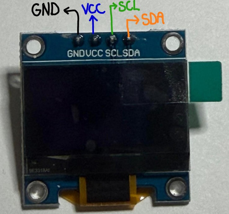
OLED display integrated into custom PCB, showing real-time cycle information
Auto-cycling displays every 5 seconds using non-blocking millis() timing
The Challenge: Evaluate different actuators for soft robotics application. Servo offers precision; air pump offers organic motion.
Tested servo motor positioning (0°, 90°, 180°) with LED feedback indicator.
Servo motor sweeping 0° → 90° → 180° with LED on during movement
Result: Servo works reliably and provides precise angular control. However, rigid arm motion doesn't align with soft robotics philosophy. Decided to pivot.
After analyzing design goals, switched to pneumatic air pump for softer, more organic motion. Pump controlled via L298N motor driver (D0 IN1, D1 IN2).
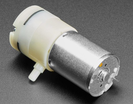
DC mini pump — generates pressure to inflate soft silicone structures
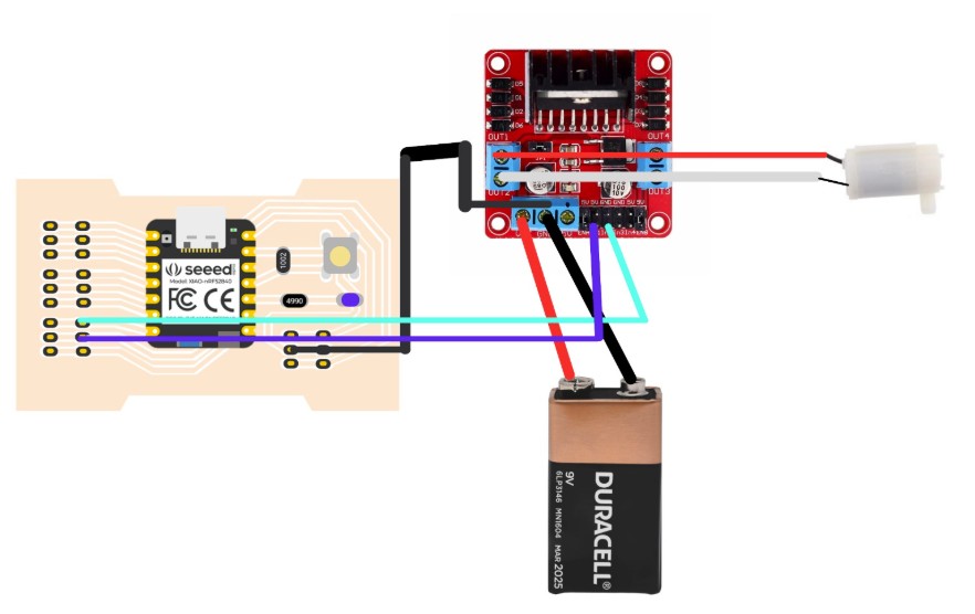
Full circuit: XIAO + L298N driver + pump + 9V battery
Air pump ON for 3 seconds, OFF for 3 seconds. Controlled via L298N driver
GPIO pins max out at 15 mA output. Air pump needs 200–500 mA to operate. Without power amplification via L298N driver, motor receives insufficient current and stalls silently. The driver acts as intermediary — XIAO sends 3.3V logic signal to L298N, which switches 9V battery current to pump. Simple but critical.
✓ Precise positioning. ✗ Rigid motion. ✗ Requires power amplification for larger actuators.
✓ Soft, organic motion. ✓ Inflates flexible structures. ✗ Slower response. ✗ Requires pump + tubing + valve infrastructure.
| Device | Interface | Current Req. | Control | Motion Type |
|---|---|---|---|---|
| DC Motor (Group) | DRV8833 driver | 0.15 A @ 100% | PWM duty cycle | Rotational, variable speed |
| OLED (Micaela) | I2C (2 wires) | ~30 mA | Digital commands | Display output, no motion |
| Servo (Andres) | Direct GPIO (PWM) | ~100 mA | Angle command | Angular, 0°–180° |
| Air Pump ⭐ | L298N driver | 300–500 mA | ON/OFF or PWM | Pneumatic, soft inflation |
© Fablab Ulima 2025 | Design: Tooplate