
What is CAM and CNC?
CAM (Computer-Aided Manufacturing) converts digital designs into machine instructions for precise manufacturing. CNC (Computer Numerical Control) machines use G-code to control movement, speed, and operations such as cutting, milling, printing, and engraving, including tools like laser cutters and 3D printers.
G-code defines axis movement (X, Y, Z), toolpaths, and tool activation, allowing the machine to execute the design accurately. In conclusion, CAM connects the digital design to the CNC machine by translating the model into G-code that the machine can interpret and execute.
Nesting
Nesting is the process of arranging parts within the machine's cutting area to use the material as efficiently as possible. By optimizing the layout, nesting reduces empty spaces, minimizes material waste, and improves cutting time.
Fab Lab ULima Safety Training
Even though I had already received safety training at Universidad del Pacífico, the training at Fab Lab ULima was essential. It helped me realize that there are many physical and technical differences between laser cutters.
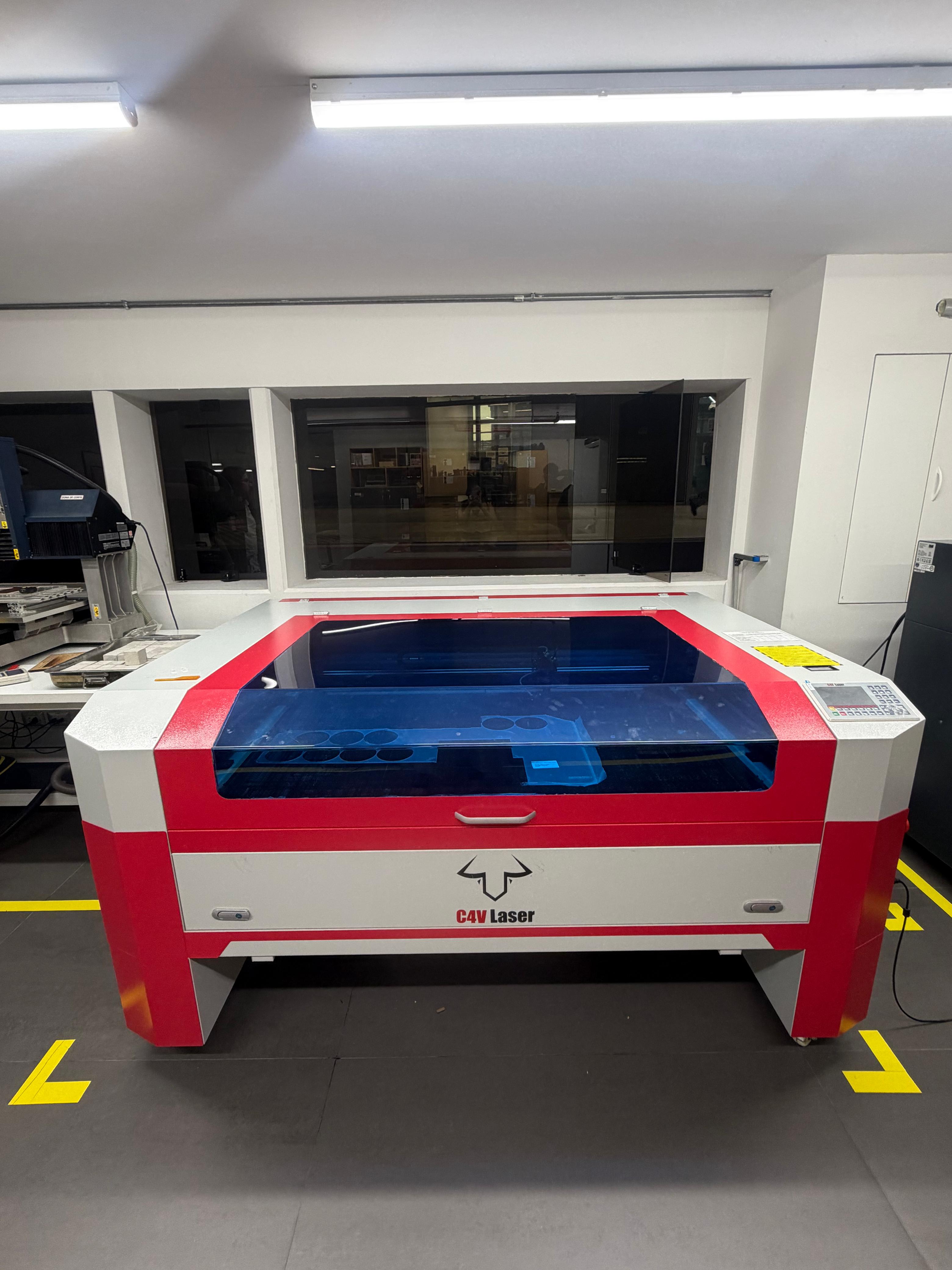
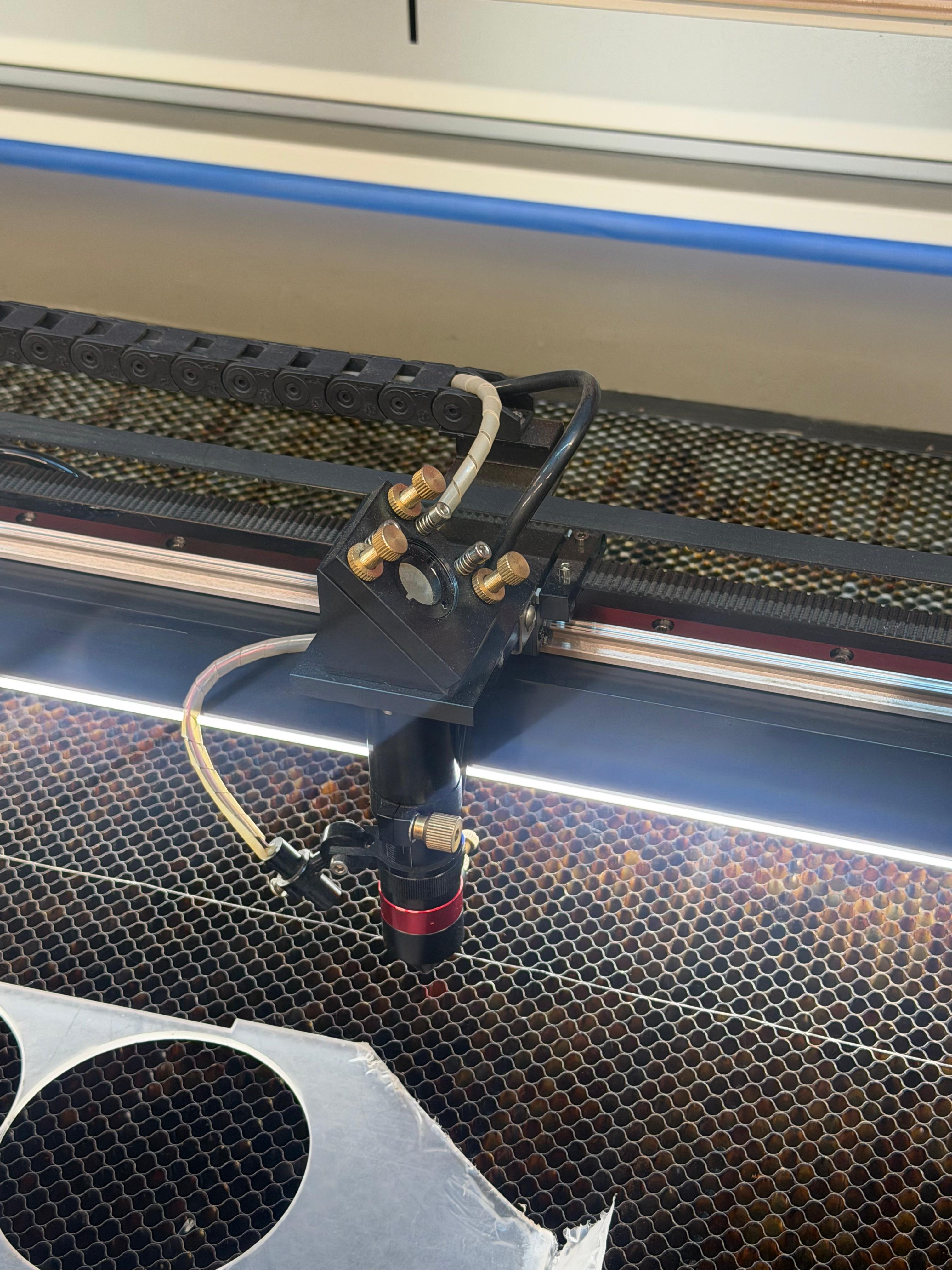
For this week's assignments, we worked with the C4V Laser 16100 Pro IA, learning its main characteristics, safety considerations, and working area.
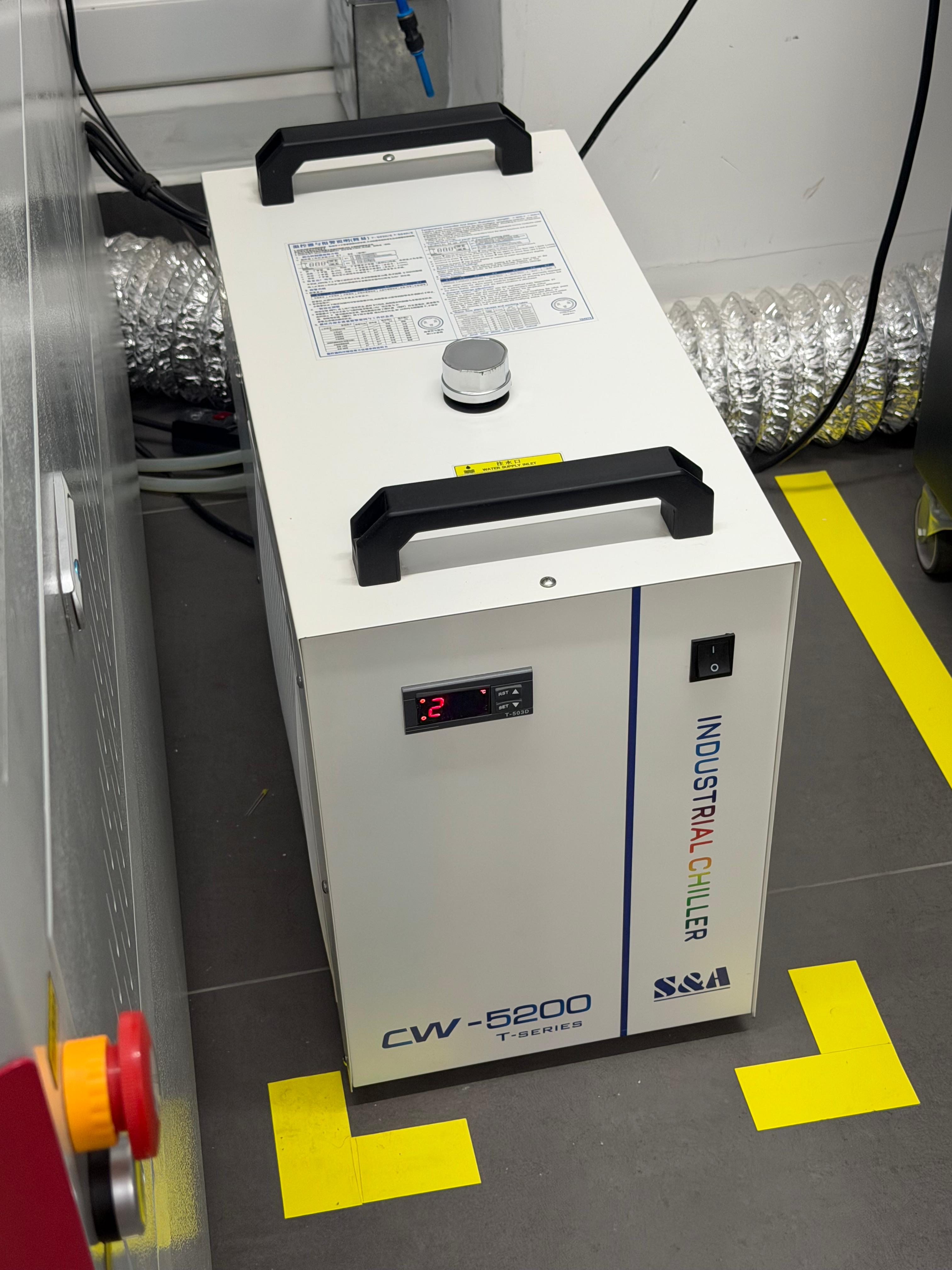
Now we explored the support equipment that allows the laser cutter to work properly and remain in good condition. On the left side of the laser cutter, there are two important machines that must be turned on when operating the laser.
The first one is the industrial chiller, which prevents the laser cutter from overheating. The coolant should be replaced every three to four months, and the chiller is turned on using the front power button.
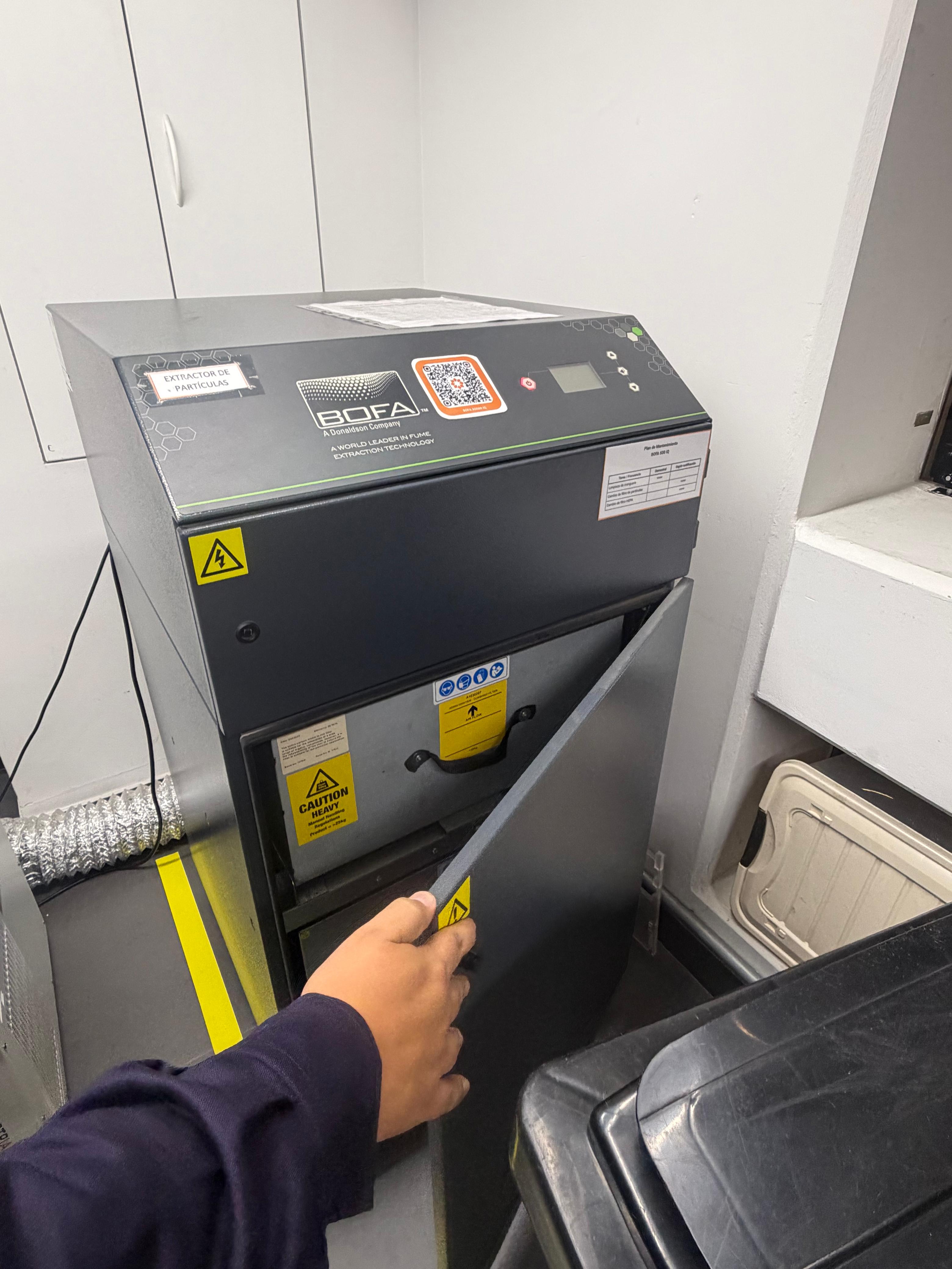
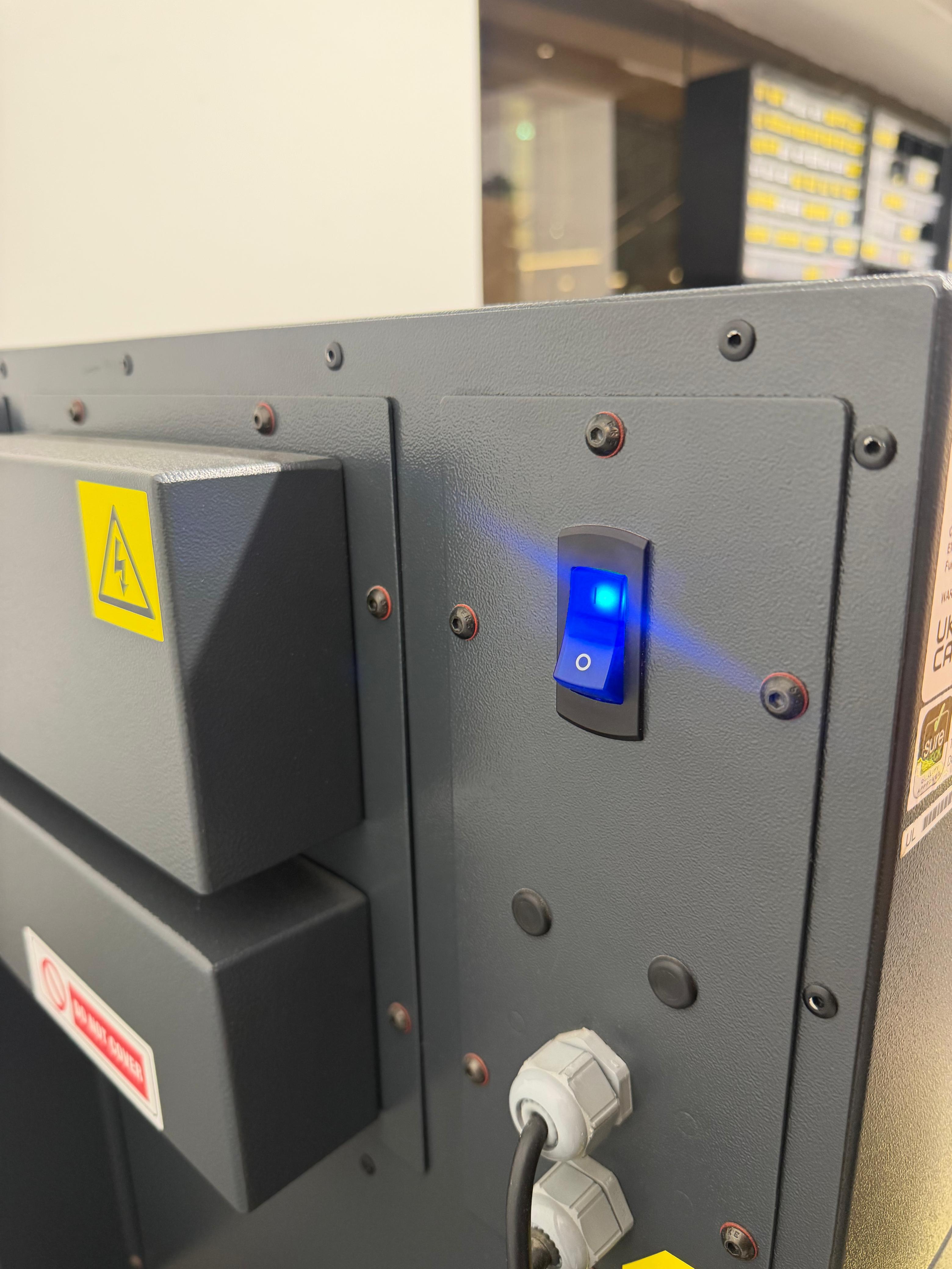
The second support system is the particle filtration unit, whose main function is to filter the smoke and fine particles generated when the laser cutter processes different materials.
Unlike basic ventilation systems that only extract air, a particle filter is designed to capture solid particles and contaminants, improving air quality and protecting both the machine and users. This is especially important when cutting or engraving materials that produce dense smoke or residues.
The unit is powered on using the blue rear button. However, the front control button is used to activate the filtration process, which is noticeably loud, and should only be turned on while the laser cutter is operating.
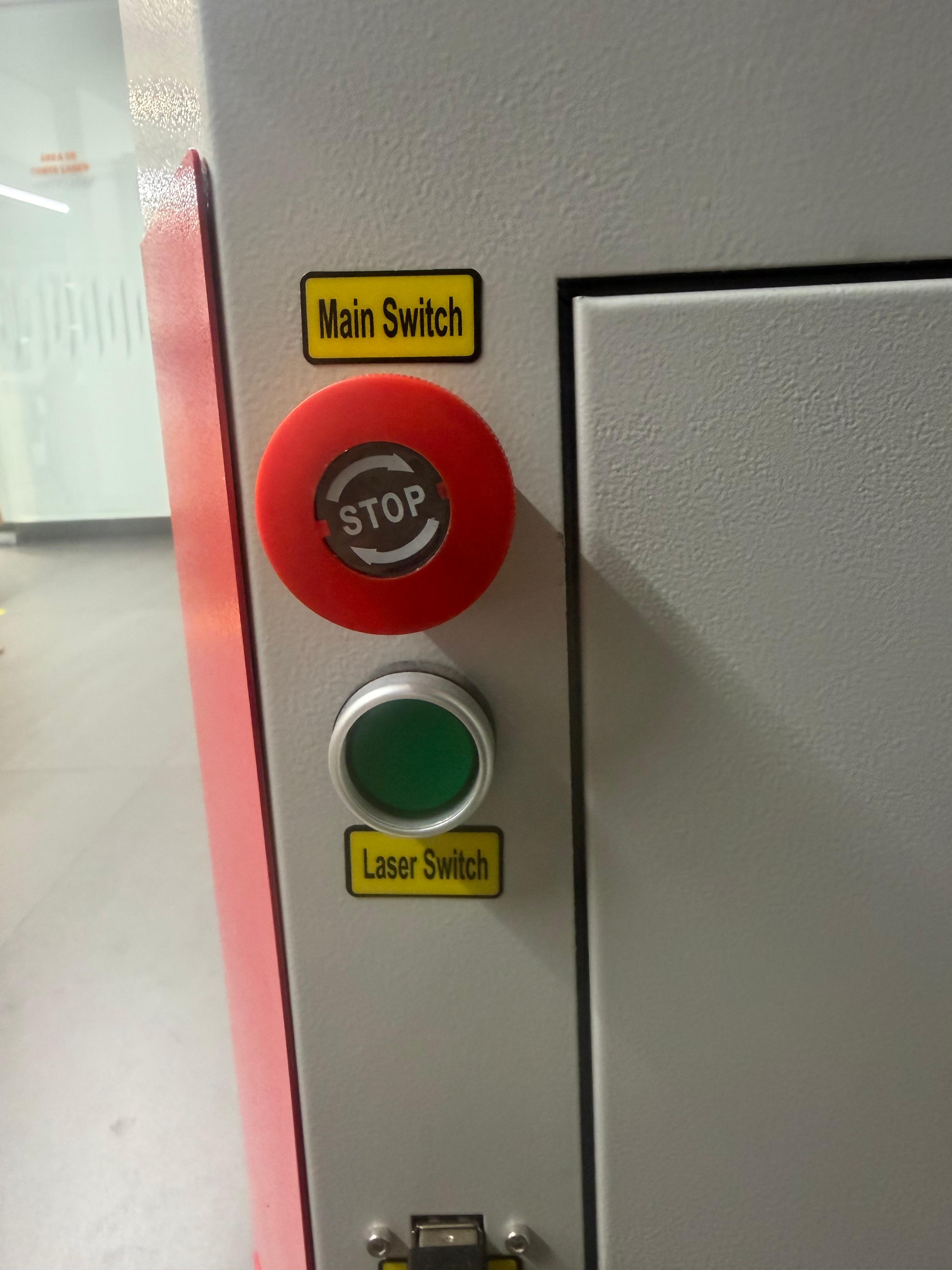
To turn on the laser cutter, the emergency stop button must first be released by twisting it, and then the green power button should be pressed.
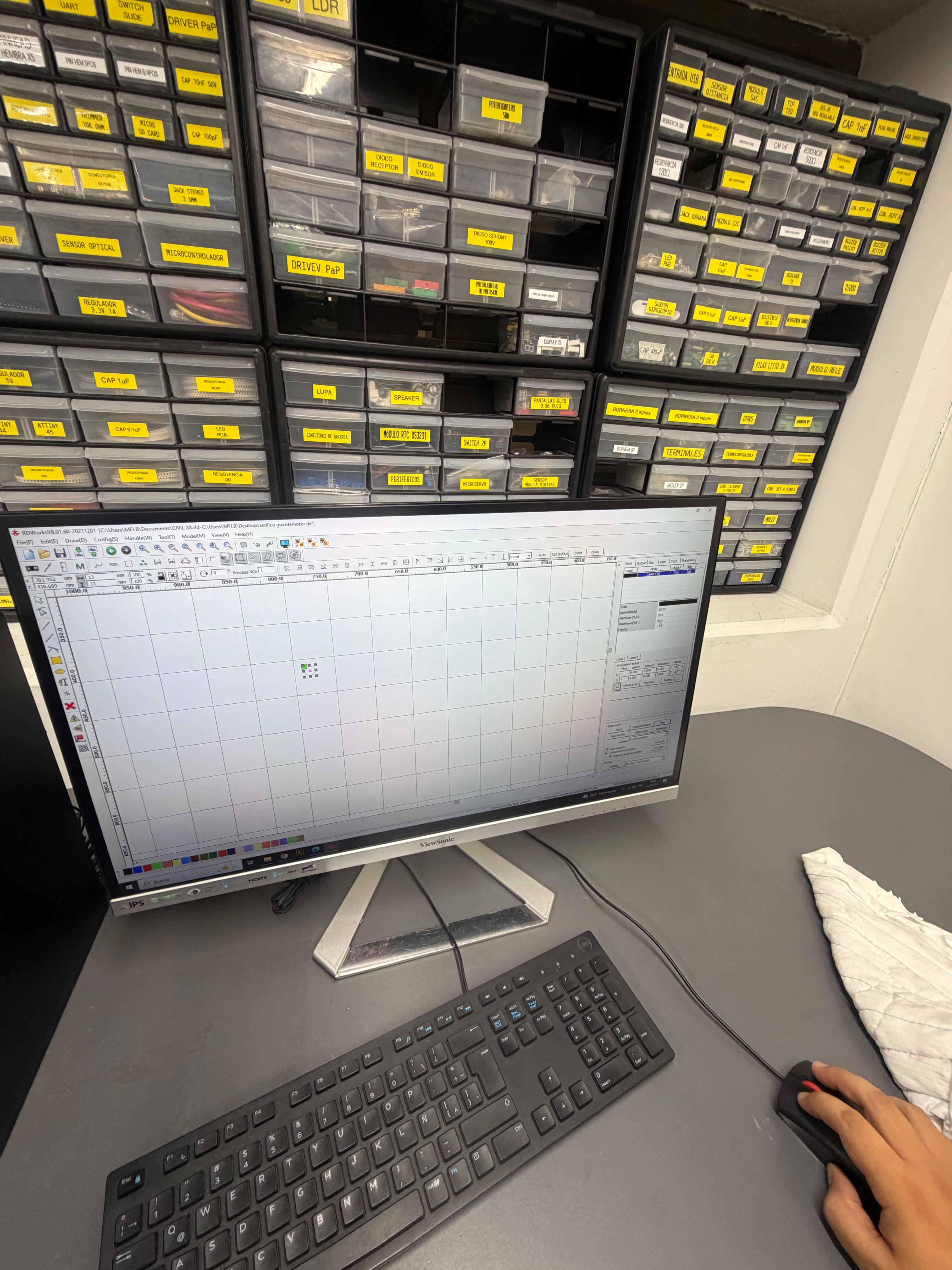
The software used to operate the laser cutter is RDWorks (RDXSolids).
⚠️ Safety note: As a safety measure, I tied my hair back to avoid accidents while operating the laser cutter.
Instructions to use the laser cutter
- First, turn on all the required machines: the laser cutter, the industrial chiller, and the particle filter.
- Then, open the lid and place the material on the cutting bed.
- Using the control panel, move the laser nozzle to the desired starting position.
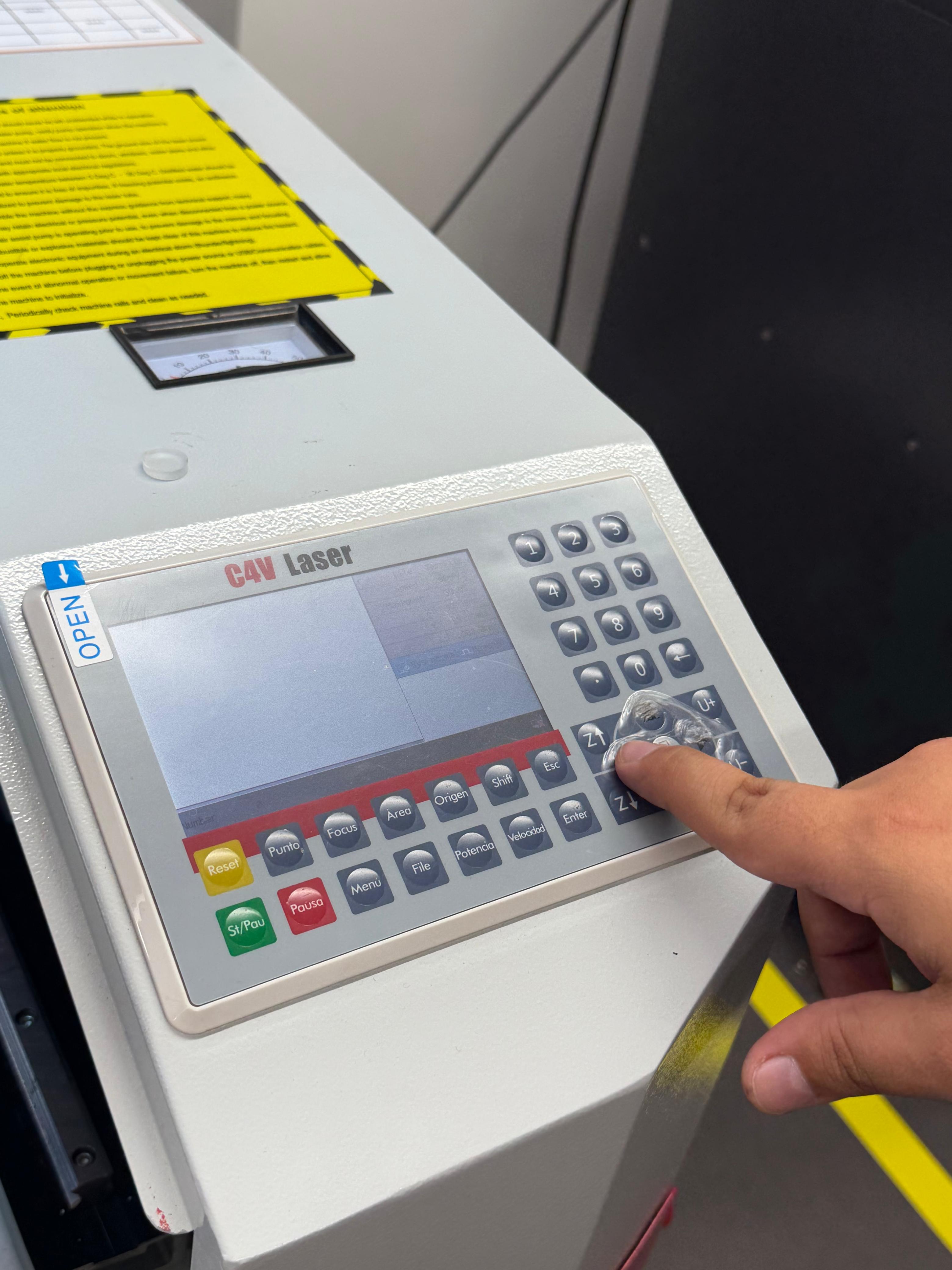
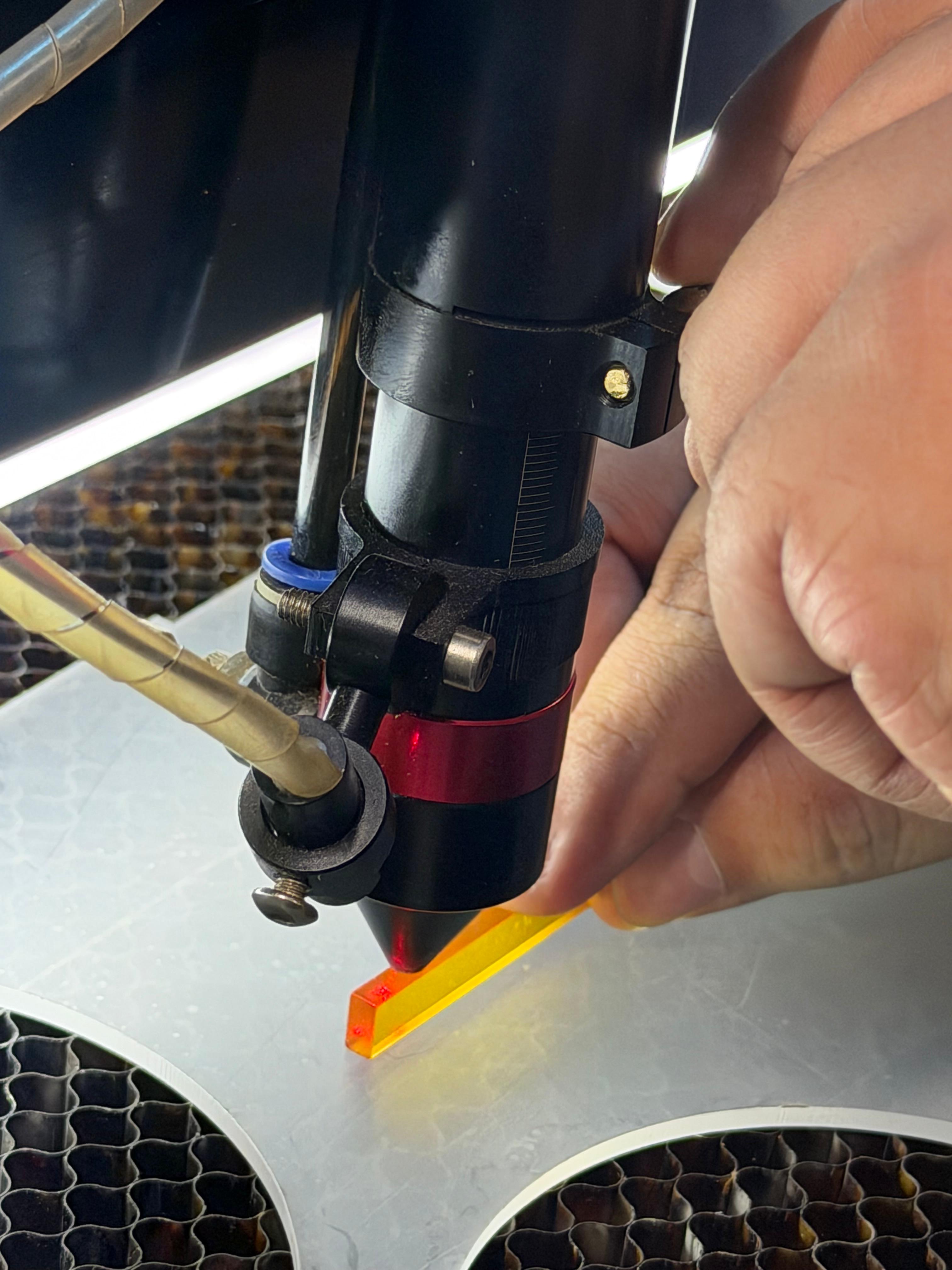
- Once the nozzle is positioned above the material, use a 1 cm ruler to set the correct focus distance.
- Loosen the upper screw of the nozzle.
- Lower it until it touches the orange ruler, as shown in the image.
- This step is essential to achieve a clean and accurate cut.
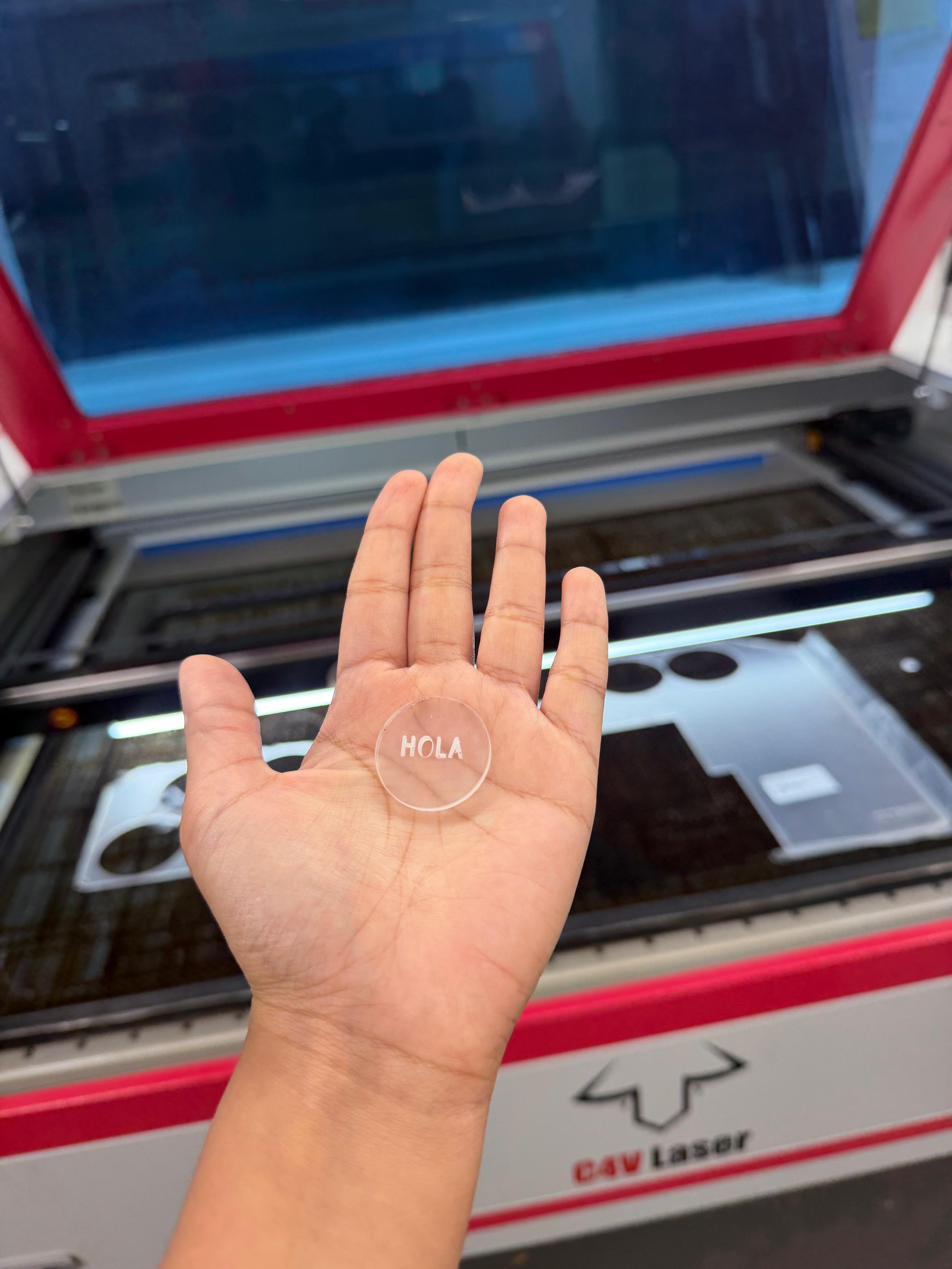
In RDWorks, it is possible to create shapes and engrave text. Different colors can be assigned to define specific cutting and engraving parameters such as power and speed.
Finally, I decided that my first laser cut would be a simple circle engraved with the word "Hola" in Spanish.
Laser Cutter Characterization
For the group assignment, I worked hands-on with the C4V Laser 16100 Pro IA, characterizing key parameters and contributing to the flexible hinge project design.
In this assignment, we explored the main parameters that affect the laser cutting process and how each variable directly influences the final result. Understanding these settings is essential to achieve clean cuts, dimensional accuracy, and good material performance.
Laser cutting depends on key parameters: focus, power, speed, pulse repetition rate (rate), kerf, and joint clearance.
Focus (Sharpness)
Focus is the distance between the laser lens and the material surface. It determines how concentrated the beam is. A correct focus produces a small, intense point for clean and precise cuts. If the focus is incorrect, the cut becomes wider, less defined, or may not fully penetrate the material.
Power (Intensity)
Power is the amount of energy delivered to the material, expressed as a percentage of the machine's capacity. In many laser cutters, the minimum effective cutting power starts around 12%, and the maximum is 100%. Higher power increases cutting ability but may cause burning if excessive. Lower power is typically used for engraving or thin materials.

Speed (Movement)
Speed refers to how fast the laser head moves across the material, also expressed as a percentage (1% = very slow, 100% = very fast). Lower speed increases heat input and cutting depth, while higher speed reduces penetration and is suitable for engraving. Power and speed must be balanced together.
Pulse Repetition Rate (Rate)
Pulse Repetition Rate is the number of laser pulses emitted per second, measured in Hz.
Joint Clearance
Joint Clearance is the intentional space between two fitting parts. It compensates for kerf and material tolerances, ensuring proper assembly without being too tight or too loose. If the joint is too small, it doesn't grab properly and lacks enough friction to hold the pieces together. If the joint is too big, it becomes loose or difficult to assemble correctly.
Kerf
Kerf is the amount of material that a laser cutter removes or vaporizes during the cutting process. This material loss directly affects the dimensional accuracy of the final parts.
The kerf value is not fixed; it varies depending on the laser cutter, the material, and the cutting parameters such as power, speed, and focus. For this reason, kerf must be measured for each specific machine and material combination.
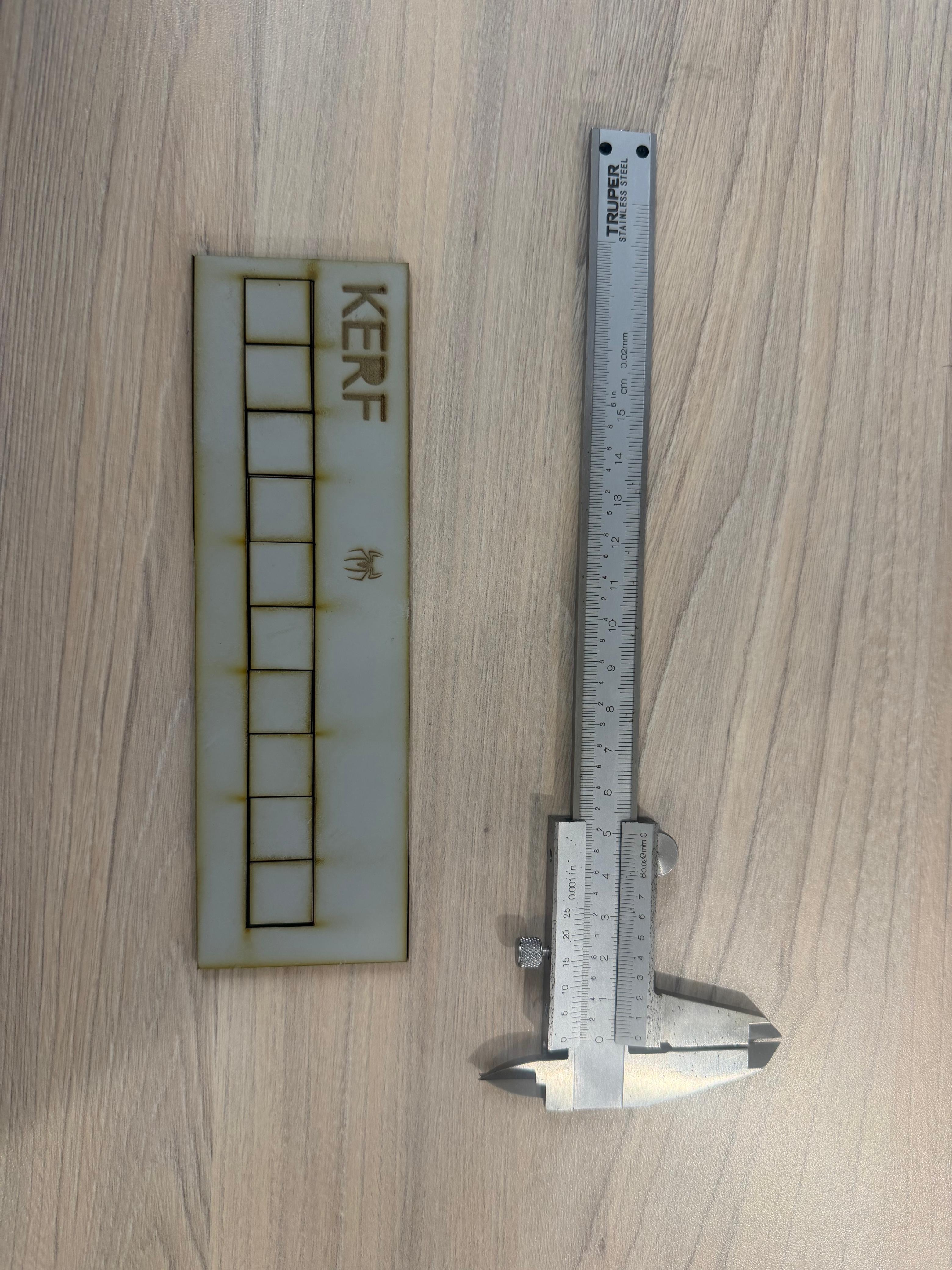
To calculate the kerf, we use the following formula: Kerf = (measured empty space) / (number of squares + 1)
In our experiment, we laser-cut multiple 20 mm squares, measured the total gap between them, and also verified the square dimensions. We then calculated an average value to obtain a more accurate kerf measurement.
The final kerf value obtained was 0.05 mm. This is relatively low, possibly because the machine is only two years old and still maintains good calibration and beam quality.
Our initial goal was to create an MDF book that could open and close using a flexible (living hinge) pattern. However, we encountered a complication in the final stage. Even though the full-scale version did not work as expected, the experience allowed us to understand the tools and theory necessary to later develop a smaller and more refined version.
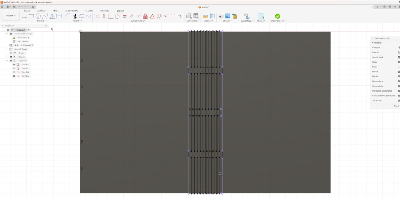
First, it is important to clearly define this type of cut. A living hinge is created from a pattern of precise cuts that transform rigid MDF into a bendable structure without breaking it. The material remains continuous, but its stiffness is reduced in a controlled area, allowing flexibility. This technique is especially useful for curved surfaces, enclosures, and dynamic components. Its effectiveness depends on spacing, pattern geometry, material thickness, and proper laser calibration.
To design it, I followed the tutorial "Autodesk Fusion 360 Tutorial: Mastering Living Hinges for Laser Cutting." In this process, I learned how to create the pattern using a structured and parametric workflow in Fusion 360. I began by understanding the relationship between cut length, spacing, and material thickness, since these proportions directly control how much the MDF can bend without failing.
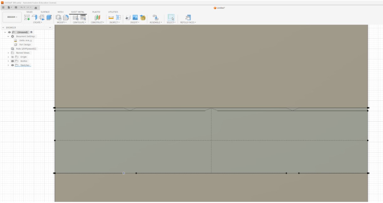
Inside the Sketch environment, I applied constraints such as Coincident, Horizontal/Vertical, Parallel, Equal, and dimensional constraints to fully define the geometry. This ensured alignment, consistency, and precision.
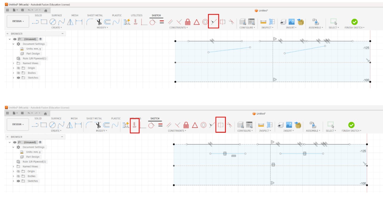
The Rectangular Pattern tool was essential, as it allowed me to replicate a single cut line evenly across the surface, guaranteeing uniform spacing and alignment.
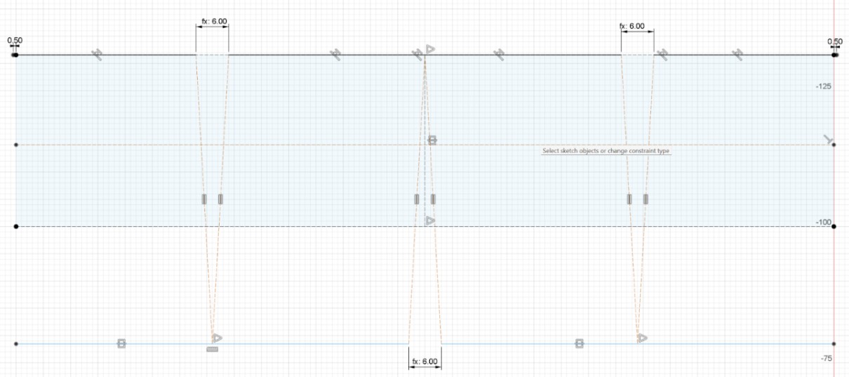
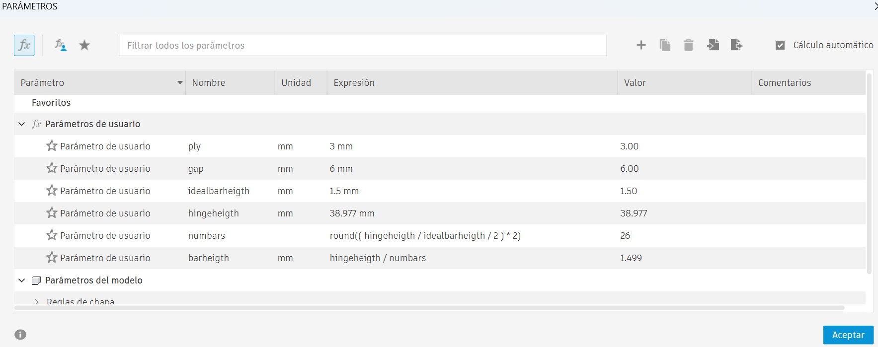
Through Modify → Change Parameters, I created a user parameter called "gap" = 6 mm to control the spacing between lines. This introduced me to parametric modeling, where dimensions are driven by variables rather than fixed numbers. If the gap value changes, the entire pattern updates automatically. This is crucial in living hinge design because spacing directly affects flexibility.
I also used the Project tool to reference edges into the sketch and maintain accurate alignment.
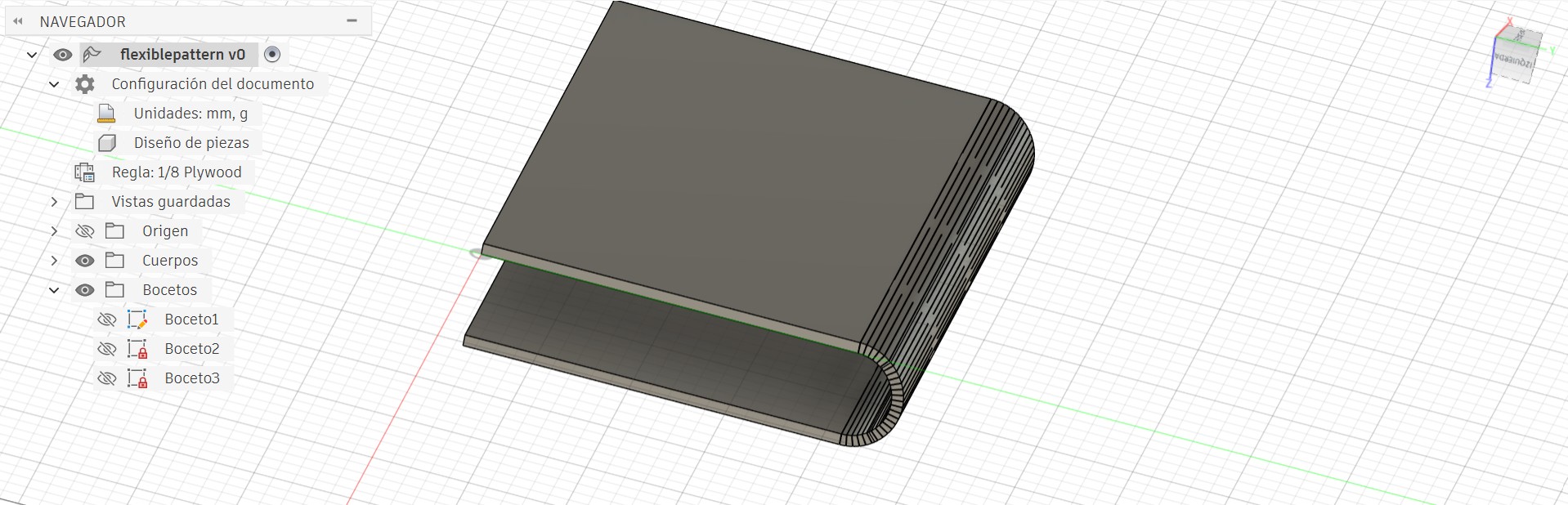
Additionally, I explored Sheet Metal tools, specifically Fold and Refold, to simulate bending along a defined line. Although folding functions belong to the Sheet Metal workspace, the parametric logic itself is built in the Sketch and Parameters section and then applied to features like patterns and folds.
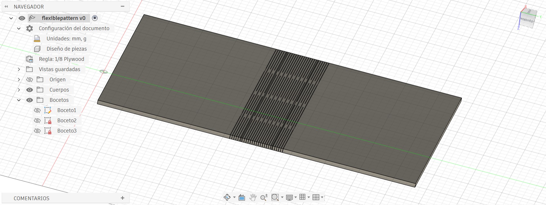
Finally, when exporting the design for laser cutting, a problem appeared. The original extruded body contained internal lines that were interpreted as cut paths by the laser software. When sending the file to the machine, these extra lines interrupted the hinge pattern. To solve this, I attempted to clean the geometry using other platforms such as Rhino and AutoCAD in order to remove the unnecessary lines before final cutting.
Despite the final complication, this process strengthened my understanding of parametric design, pattern creation, and digital fabrication workflow, giving me the foundation to successfully redesign the project at a smaller scale.
Parametric Construction Kit
After gaining experience with the flexible hinge project, I felt confident enough to develop my own construction kit. I wanted to design something minimalistic yet functional — a dynamic system that could easily connect and adapt to different configurations.
The concept was to create a circular base piece with three different slot connections, allowing multiple assembly possibilities. This simple geometry provides versatility, enabling the pieces to be combined in various ways while maintaining structural stability.

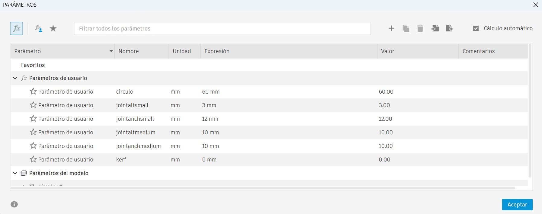
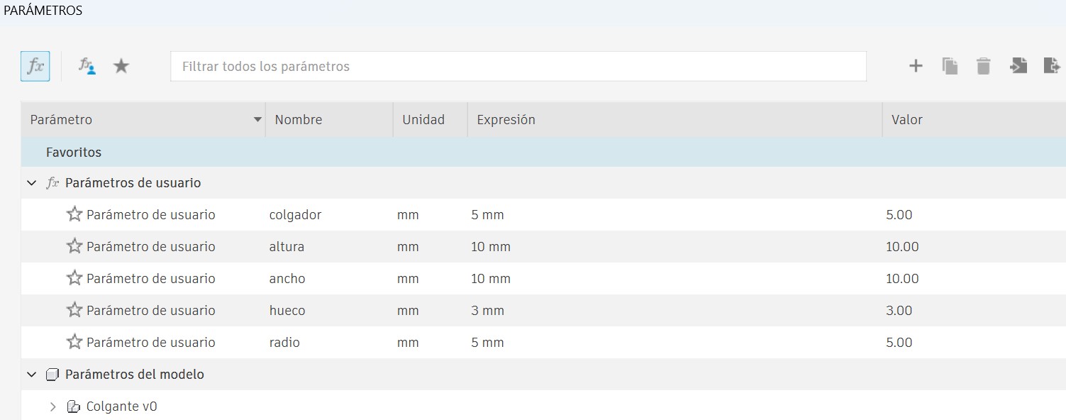
On this occasion, I used Fusion 360 to develop the kit. The complete set consists of four different pieces, whose dimensions vary according to the parameters defined by the user. This means that by modifying a parameter, all related dimensions update automatically, maintaining proportionality and correct fit between parts.
To create user-defined parametric dimensions in Fusion 360, we go to the Solid tab, then select Modify, and choose Change Parameters.

Manufacturing Process
I established user parameters for all critical dimensions:
- Material thickness: 3 mm (cast acrylic)
- Kerf compensation: 0.05 mm (measured from group assignment)
- Slot width formula: material thickness - (kerf × 2)
- Diameter and spacing: Controlled parametrically
This approach meant that changing one parameter would automatically update all related dimensions, ensuring consistent fit and assembly across all pieces.
Step 2: Piece Design
Main Piece - Circular Base

Medium Joint

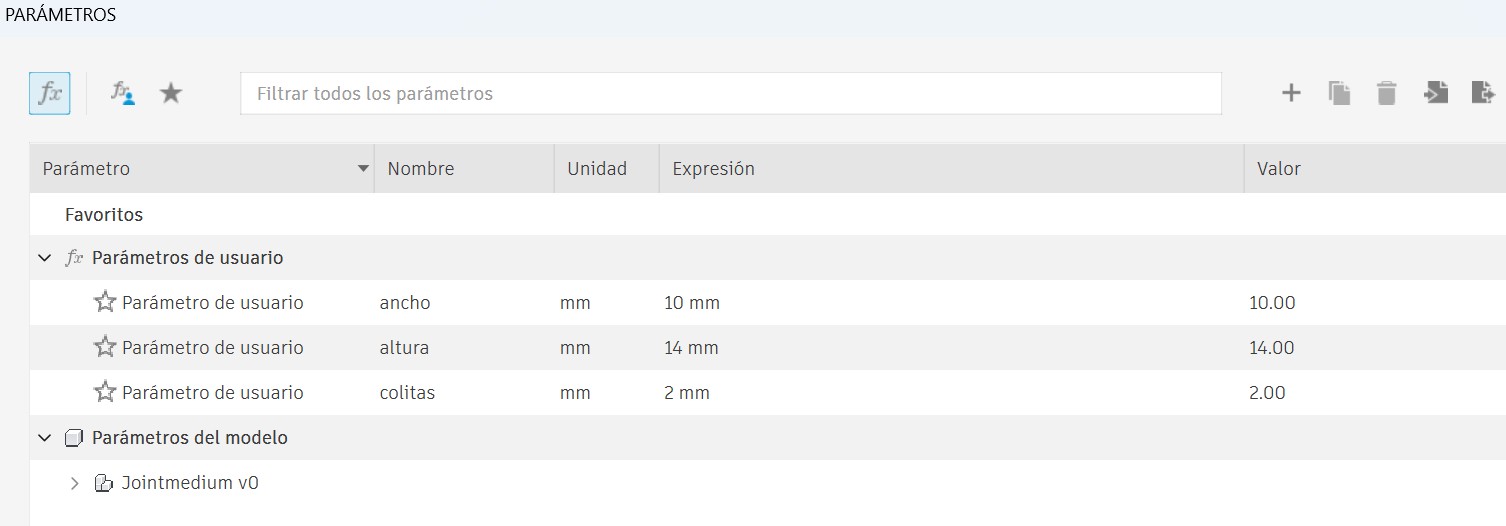
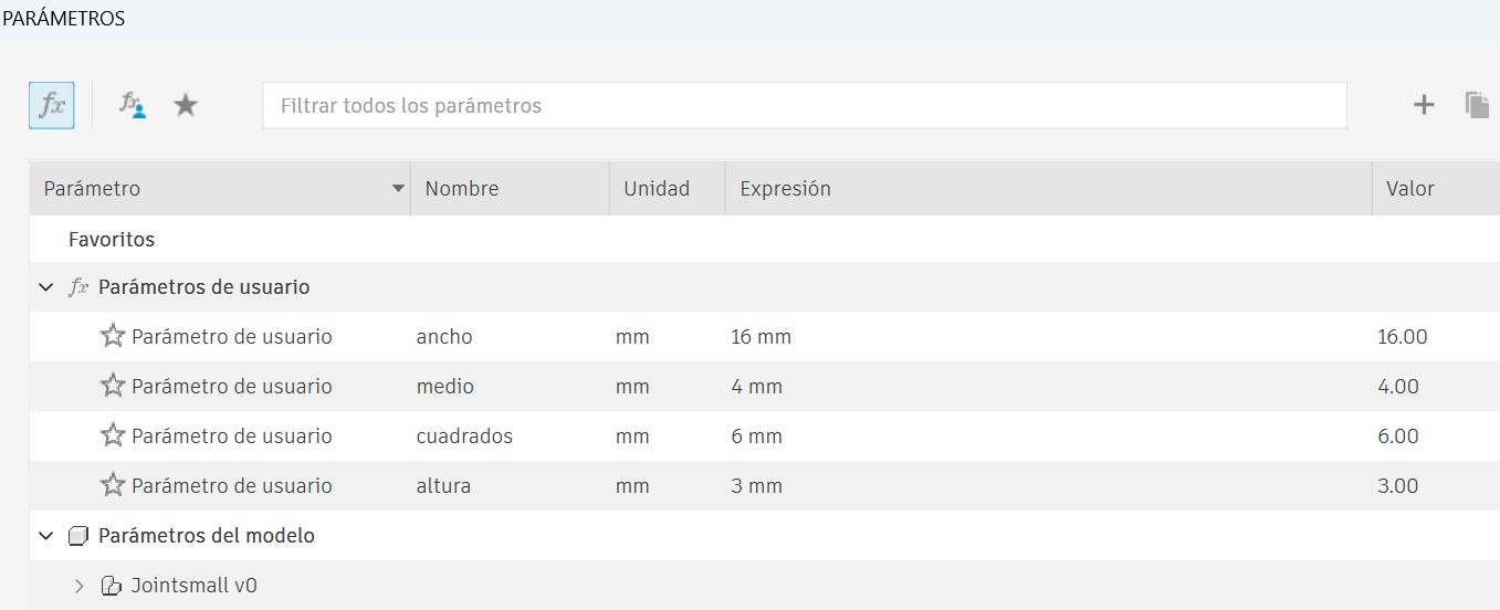
Small Joint

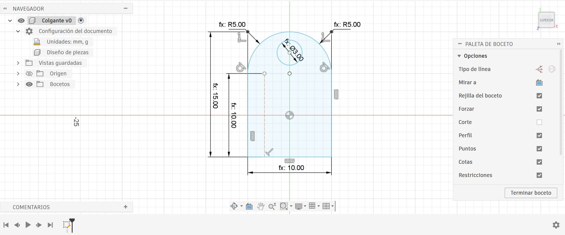
Earring Extension
Step 3: Laser Cutter Preparation
Workflow:
- Export design as DXF from Fusion 360
- Import into RDWorks software
- Assign different colors: Red = cutting, Other colors = engraving
- Verify focus distance using 1 cm ruler method
- Arrange pieces in cutter bed (nesting) to minimize material waste
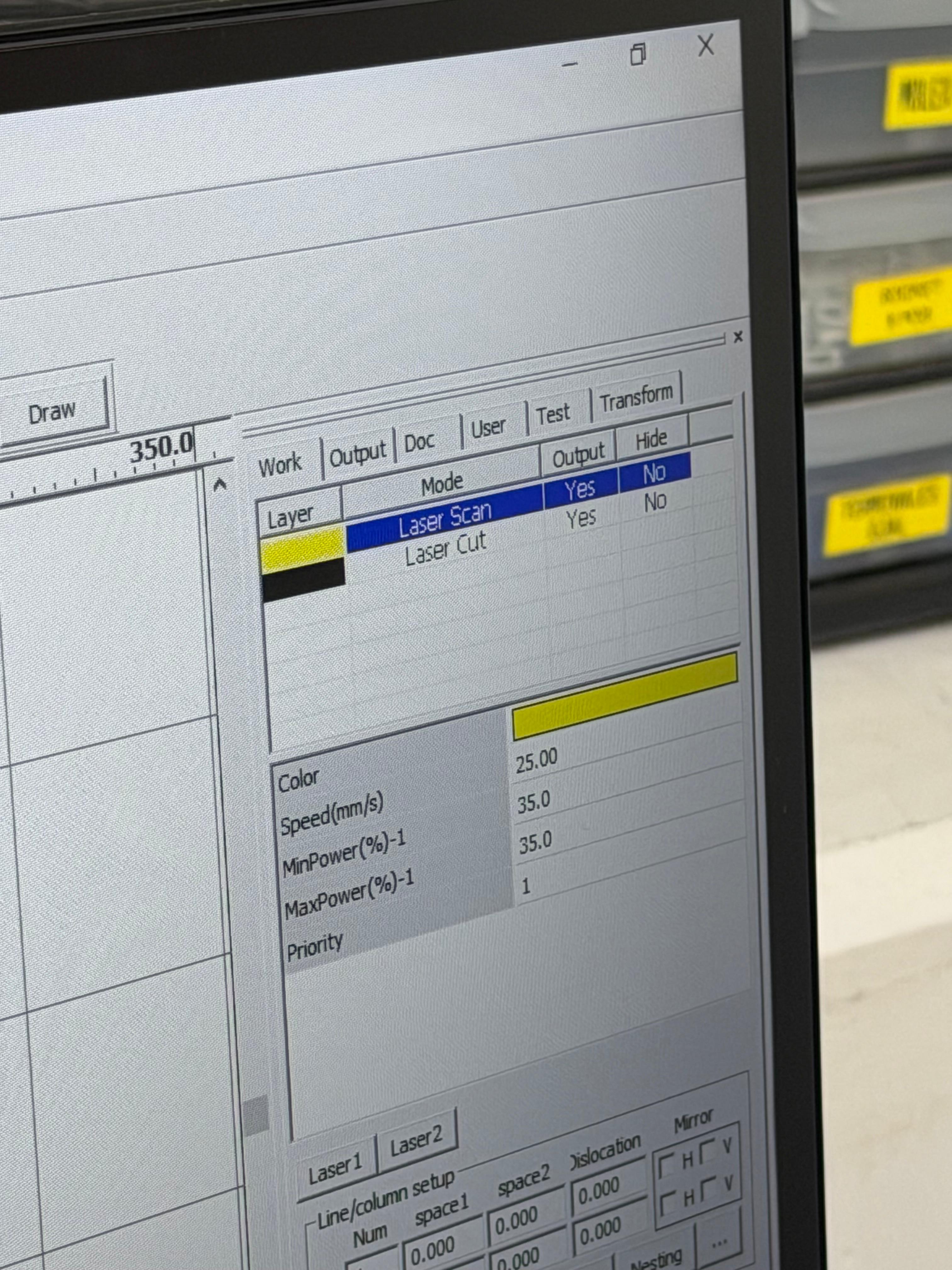
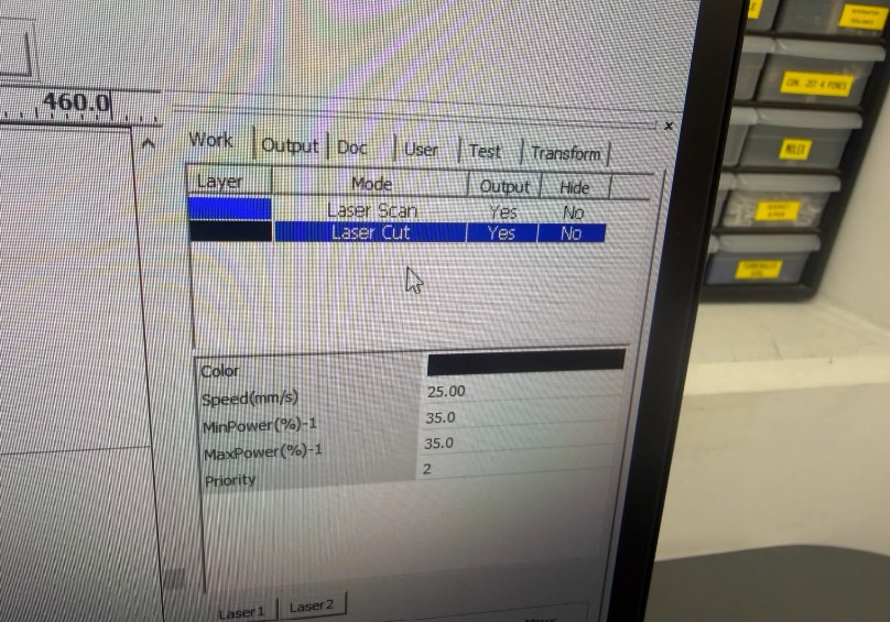
Step 4: Laser Cutting Parameters
Material: 3 mm Cast Acrylic | Machine: C4V Laser 16100 Pro IA | Software: RDWorks
- Power: 35%
- Speed: 25%
- Priority/Rate: 2
- Passes: 1
- Mode: Laser Cut
- Material: Acrylic 3mm
- Output: Yes
- Test Mode: No
Why these values? Through experimentation and multiple test cuts, 35% power at 25% speed proved optimal for clean cuts in 3 mm acrylic without charring or excessive heat. This lower power/speed combination, combined with Priority 2, produces excellent edge quality and precise tolerances. The single-pass cutting (1 pass) ensures efficiency while maintaining cut integrity.
Here's the actual RDWorks configuration used for the final cuts:
Step 5: Tolerance & Fit Testing
Tolerance applied: Kerf compensation of 0.05 mm per edge, subtracted from all slot widths.
Result: ✅ Sufficient for a perfect press-fit joint. Pieces fit snugly without requiring force, and could be assembled and disassembled multiple times by hand without any degradation.
Manufacturing & Assembly Process (Video)
Here's a complete walkthrough of the laser cutting and assembly process:
Step 6: Troubleshooting & Problem Solving
Solution Process:
- Reran the kerf measurement test specifically for 3 mm acrylic at 85% power, 30% speed, 25 Hz
- Confirmed the kerf measured 0.05 mm at these settings
- Created test pieces with multiple slot width variations (±0.1 mm increments)
- Cut test pieces at the same parameters to identify the optimal tolerance window
- Found that an additional +0.02 mm clearance was needed for smooth assembly
Final Adjustment: Added 0.02 mm extra clearance to the slot width formula. The second cut produced perfect press-fit joints that assembled smoothly by hand without any gaps or excessive force required.
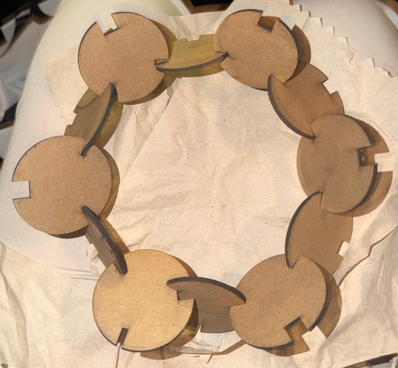
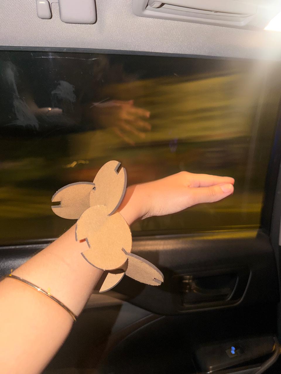
Step 7: Assembly Examples
The kit assembled successfully into multiple configurations. All pieces fit together correctly, and the tolerances held after multiple assembly/disassembly cycles.
1. The Circle
2. The Bracelet
3. Pokey Mario Bros (The yellow thing)
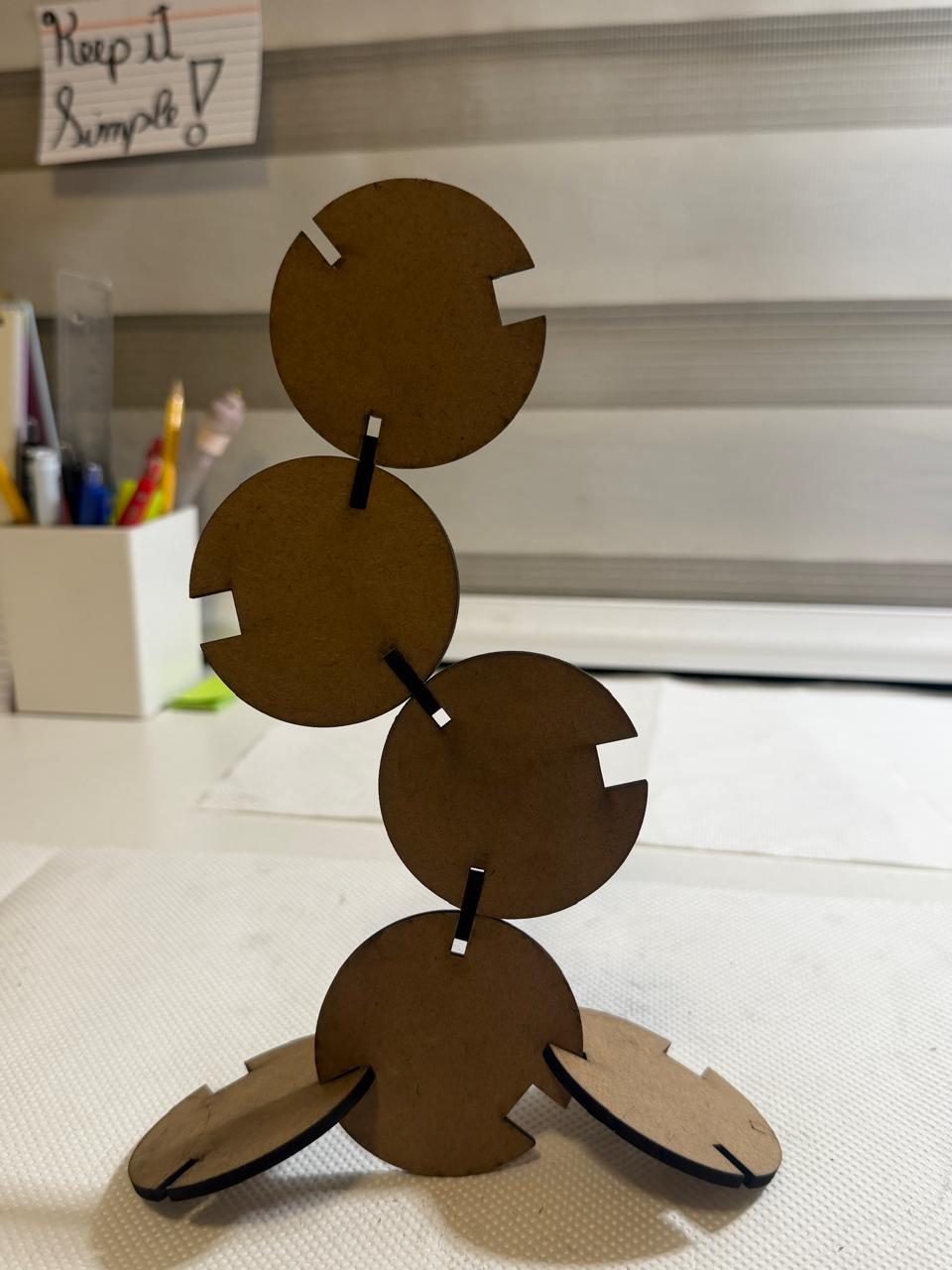

4. Crab Squad
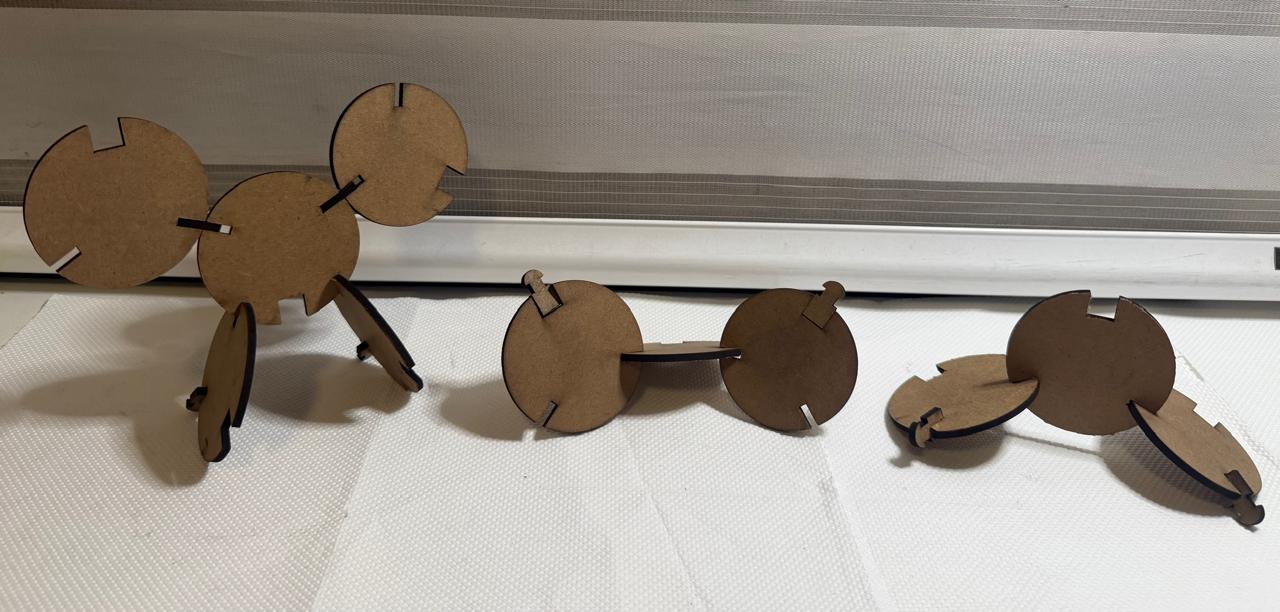
5. Scorpion
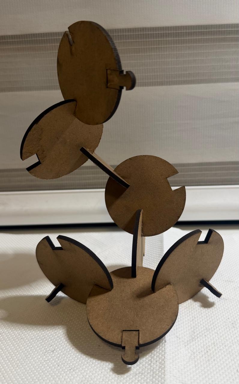
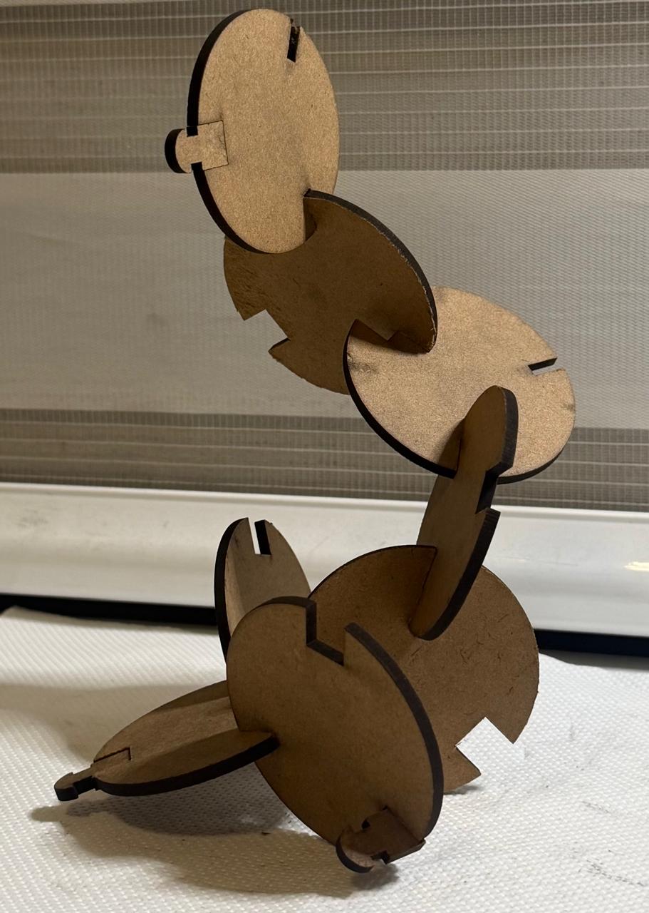
6. Earrings (My favorite)
Vinyl Cutting
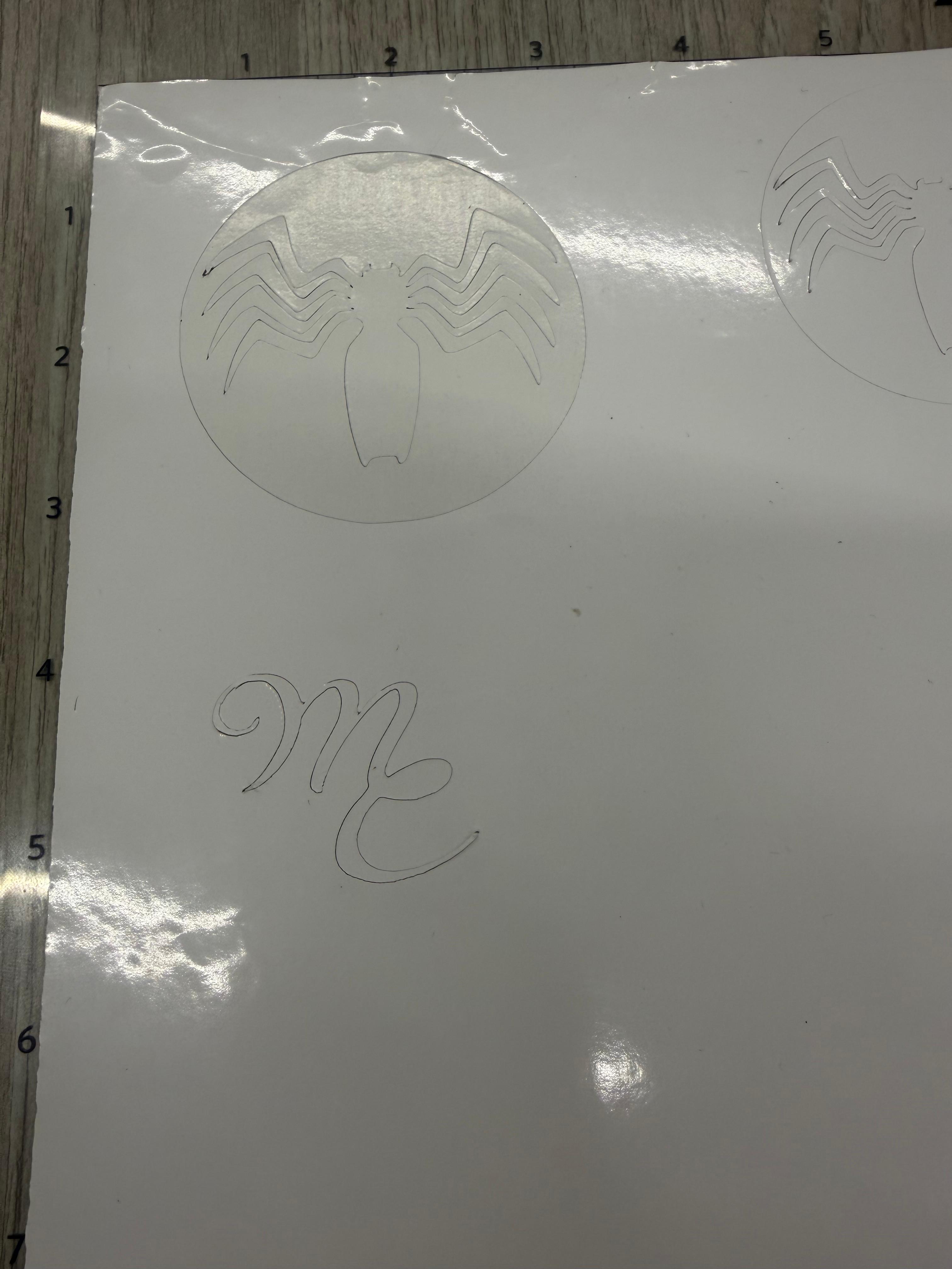
For this assignment, I decided to use my personal website logo, which I designed myself. I wanted to test whether my custom lettering would work properly as a vinyl sticker. Since the original drawing was created in raster format, I first imported it into Inkscape and vectorized it.
This step was essential because raster images would be interpreted as small points by the vinyl cutter, producing dotted or irregular cuts. By converting the logo into vector format, I ensured clean, continuous strokes suitable for cutting.
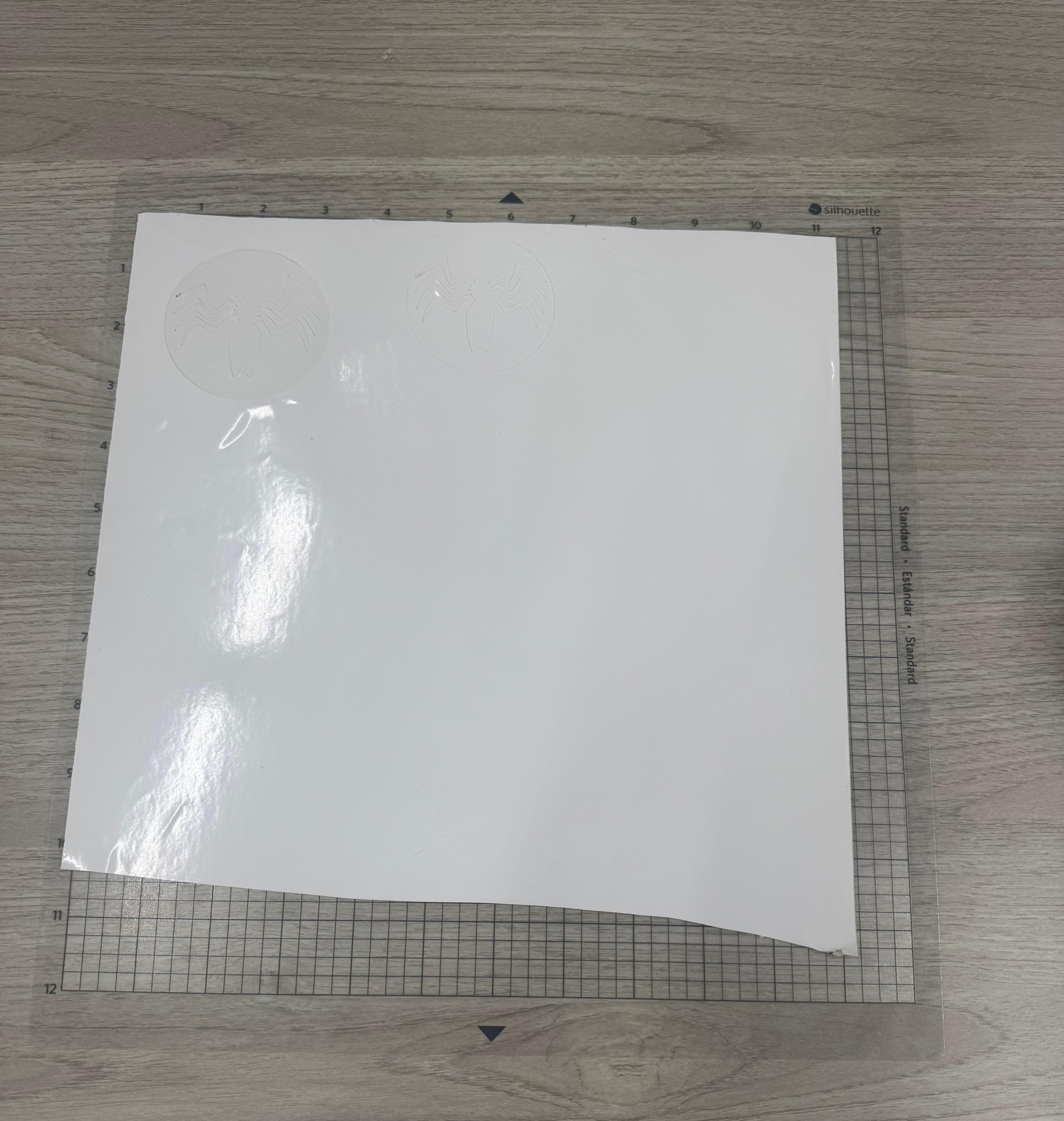
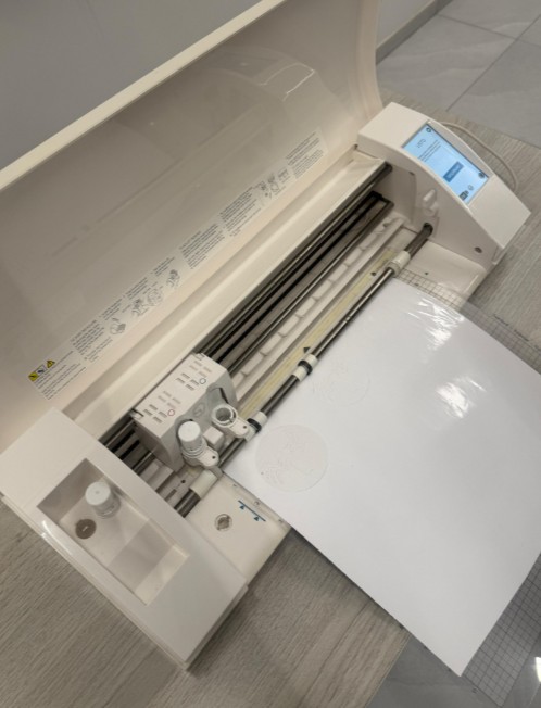
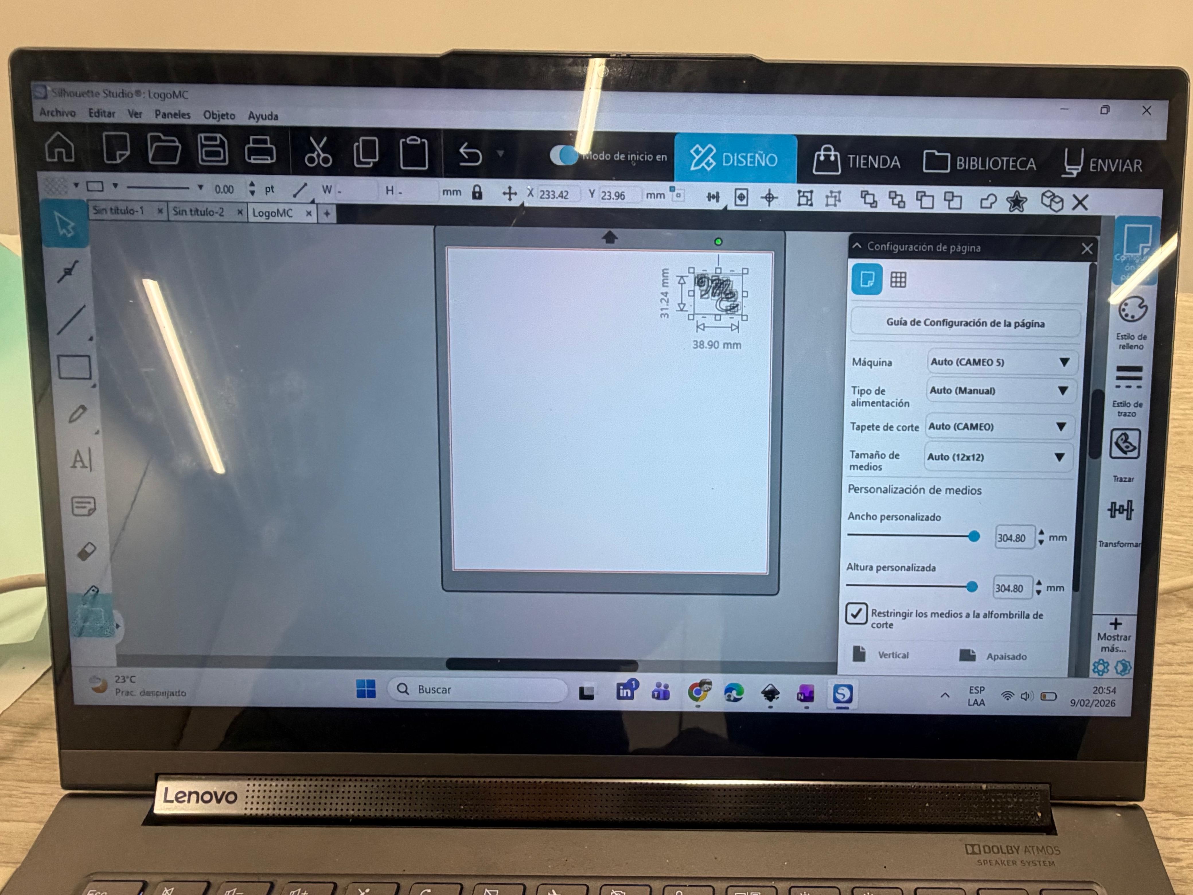
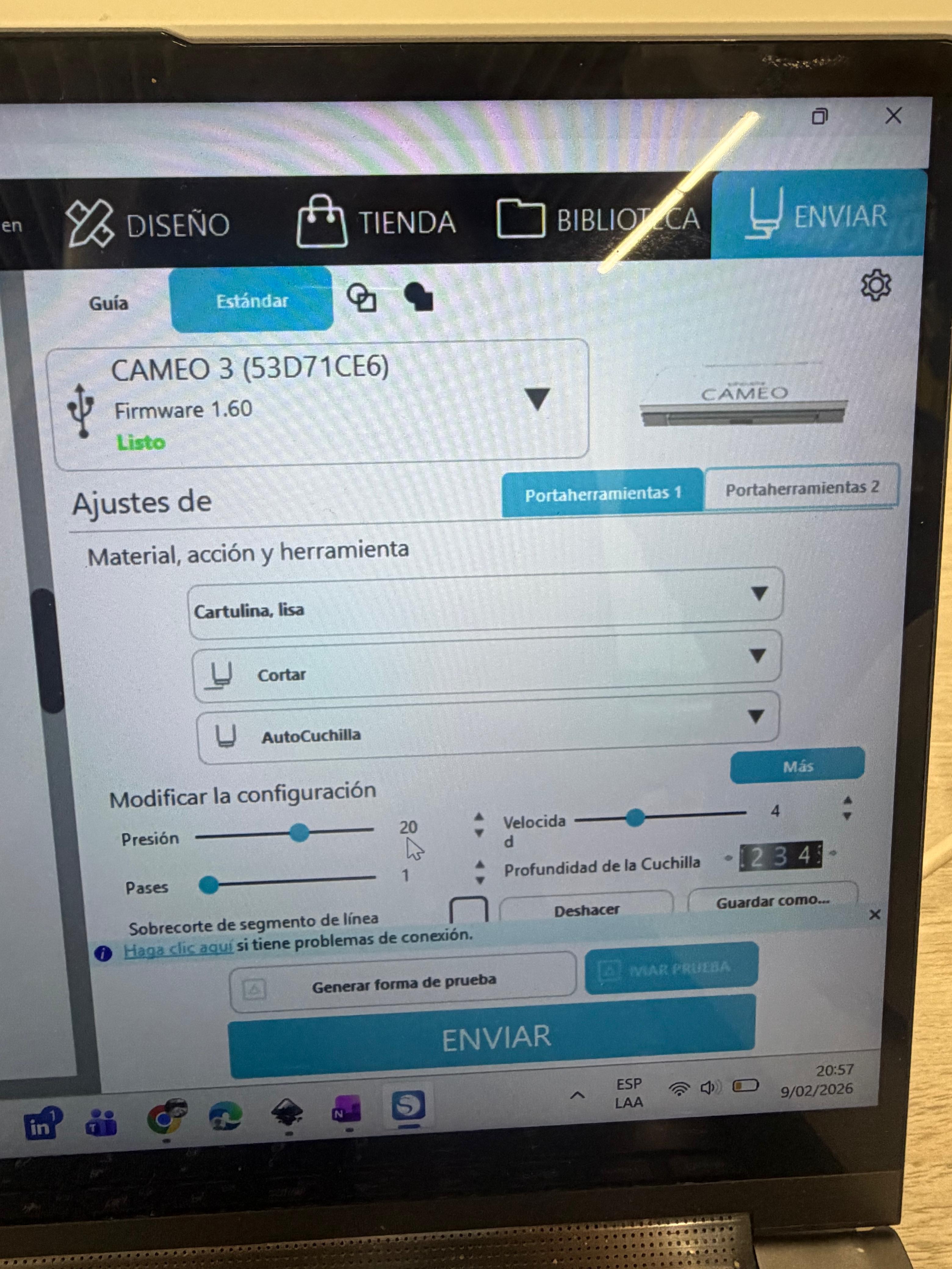
The vinyl cutter available in the lab is the Silhouette CAMEO, and to manage the cutting process I downloaded Silhouette Studio. I imported the strokes in .DXF format, centered the design on the workspace, and selected the correct material settings. In this case, I used glossy vinyl, with a blade depth of 3. Unlike the laser cutter, where power and speed must be carefully calibrated, here I kept the default speed and force settings since they were appropriate for vinyl.
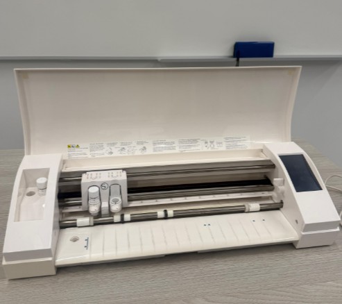
To prepare the machine, I inserted the vinyl sheet, carefully aligning it with the blue arrows on the cutter. While holding the material in place, I pressed the load button so the machine could grip and align it properly. After confirming placement in Silhouette Studio, I sent the design to cut.
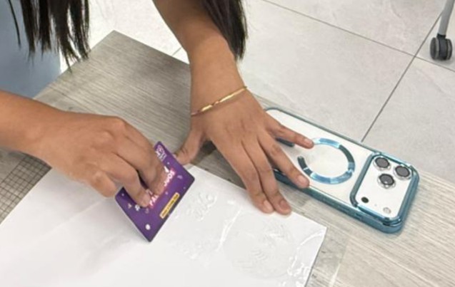
Application Process
After cutting, I applied transfer tape (vinyl transfer film) over the sticker so it would adhere to the tape and could be moved easily. I then positioned it on my phone case, pressed firmly using a card to distribute pressure evenly across the surface, and slowly removed the transfer tape. The vinyl adhered successfully.
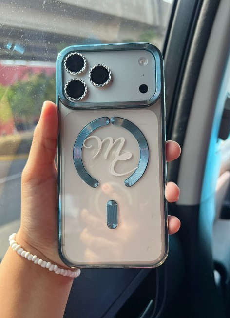
Result: The vinyl adhered perfectly to the phone case. The logo design is clean and sharp, with no tearing or registration issues. The final sticker has a glossy finish that matches the phone case aesthetic beautifully.