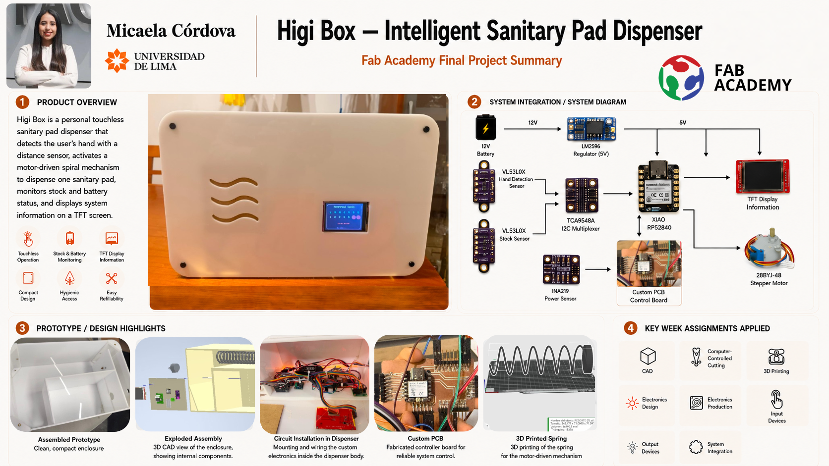
What Does It Do?
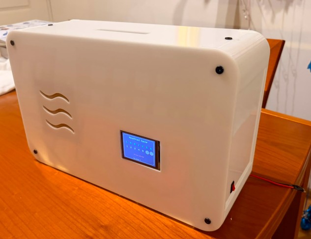
HigiBox is a compact menstrual care dispenser that combines mechanical movement, proximity sensing, stock monitoring, battery management, and digital feedback. It stores sanitary pads vertically and dispenses them through a motorized spiral mechanism when the user places their hand near the device.
Core Functions
- Touchless Activation: VL53L0X proximity sensor detects the user's hand without physical contact
- Autonomous Dispensing: Motor-driven spiral rotates to release one sanitary pad per gesture
- Stock Monitoring: Distance sensor tracks product availability in real-time
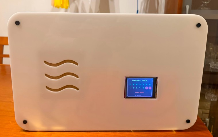
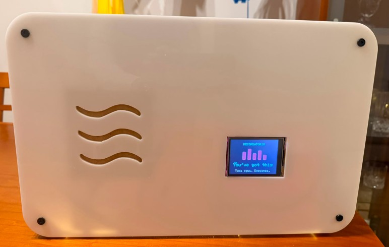
- User Interface: 2.8-inch TFT display shows cycle tracking, battery status, stock level, and motivational messages
- Power Management: Rechargeable 12 V battery with USB Type-C charging; INA219 sensor monitors voltage and power consumption
- Smart Connectivity: Wi-Fi integration for NTP time synchronization and future app connectivity
The Experience
Unlike traditional dispensers, HigiBox creates a more private and supportive experience by combining mechanical reliability with digital empathy. The device is designed for personal use in homes, dorms, or private bathrooms—creating a discreet, always-available solution for menstrual product access.
Who's Done What Beforehand?
Commercial Vending Machines
Commercial sanitary pad vending machines already exist in universities, schools, workplaces, and public restrooms worldwide. These large-scale dispensers use mechanical spirals and motorized systems to release products efficiently.
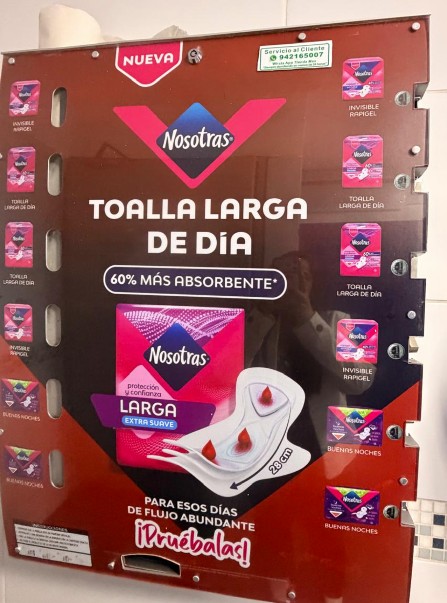
However, commercial dispensers are typically large metal machines for public use. They require coins or buttons, offer no personalization, and lack features like menstrual-cycle tracking or battery feedback.
Personal Product Organizers
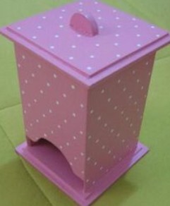
Most personal-use products found online are simple organizers that store pads vertically or horizontally. These require manual removal and refilling with no sensors, monitoring, or digital interface.
The Gap — HigiBox Innovation
HigiBox adapts commercial vending principles into a personal device. Key differentiators:
Hand detection, no buttons needed
Compact for bathrooms, dorms, offices
Cycle tracking + battery + stock info
Designed in Fab Lab with digital tools
Design Process
Conceptual Phase: Sketches & Dimensions
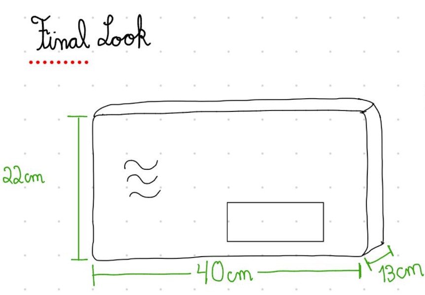
Design began with hand sketches exploring the relationship between form, function, and user interaction. I defined initial dimensions based on product storage requirements and component sizing:
40 cm — Accommodates vertical pad storage and spiral mechanism
22 cm — Allows display visibility and hand access
13 cm — Minimizes footprint while fitting electronics
Functional Zoning
The prototype was divided into distinct functional regions:
- Upper Section: Product storage, spiral mechanism, motor, hand-detection sensor
- Middle Section: TFT display interface, visual feedback
- Lower Section: Electronics enclosure, battery, PCB, power modules, wiring
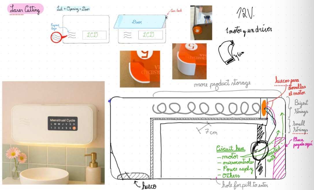
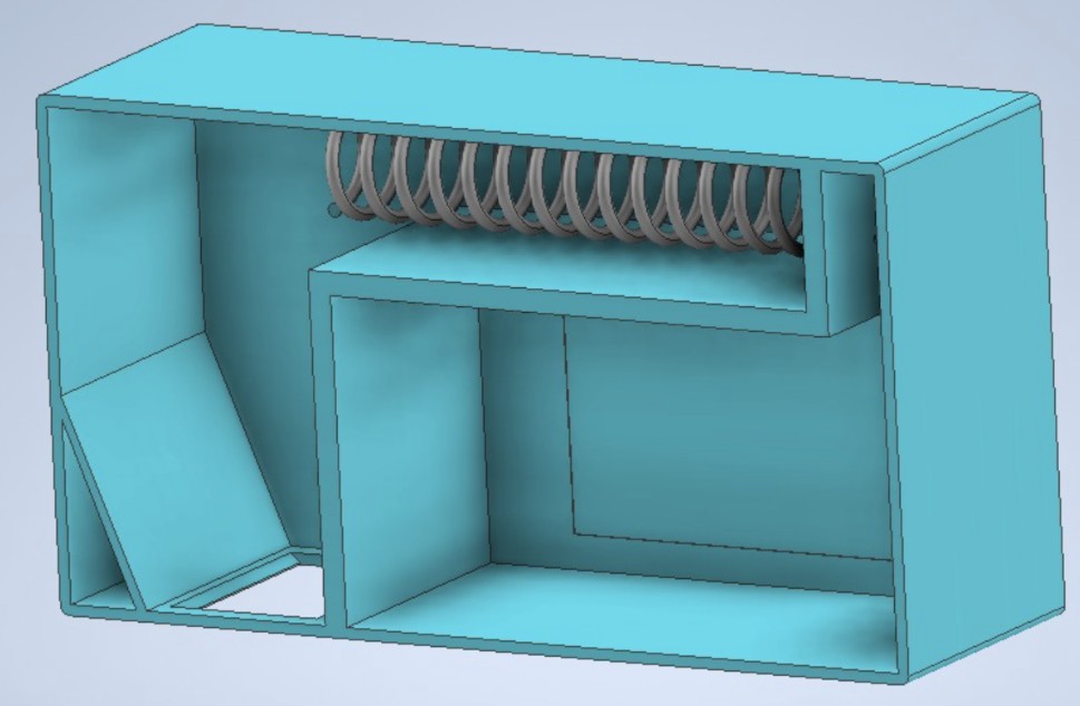
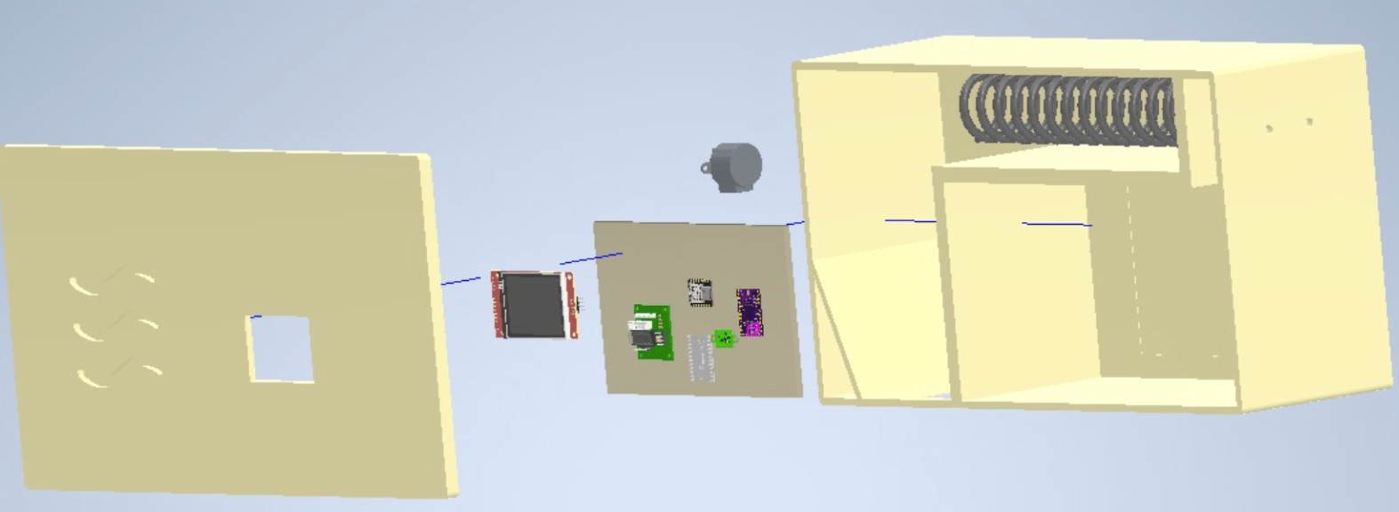
After this first draft, I continued working in Fusion 360, which became the main software for refining the structure.
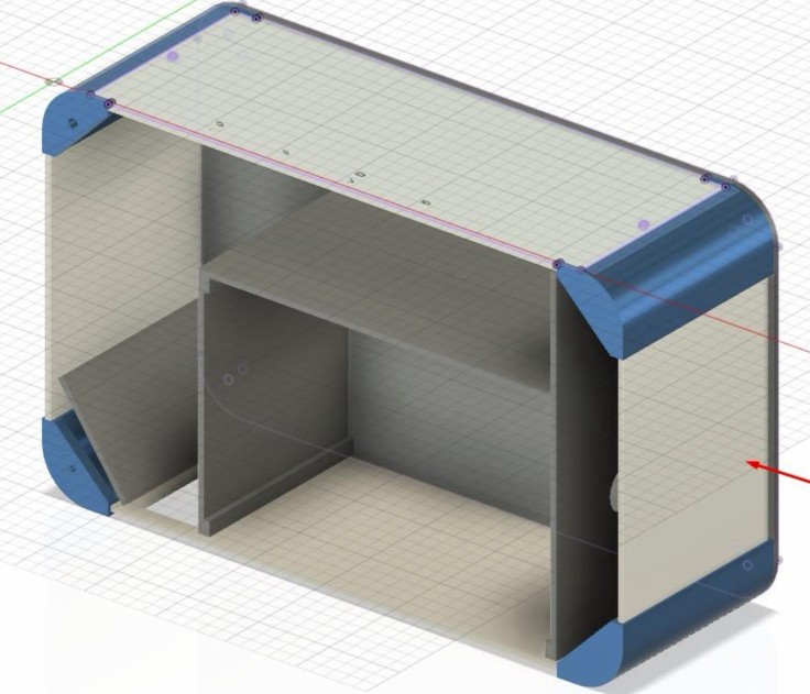
Digital Modeling Workflow
The design evolved through two CAD platforms:
- Autodesk Inventor: Initial draft to establish proportions and internal space
- Fusion 360: Refined modeling, component assembly, sensor placement, mechanical details
3D component models (microcontroller, sensors, motor, battery) were integrated to ensure real-world fit. After the first physical assembly, the model was updated to add internal guide wings that prevent sanitary pads from deviating during dispensing.
System Integration
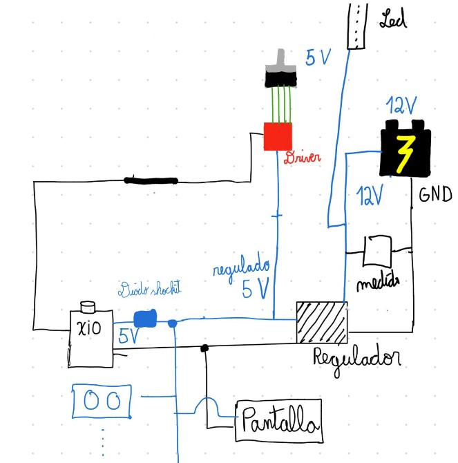
Mechanical System
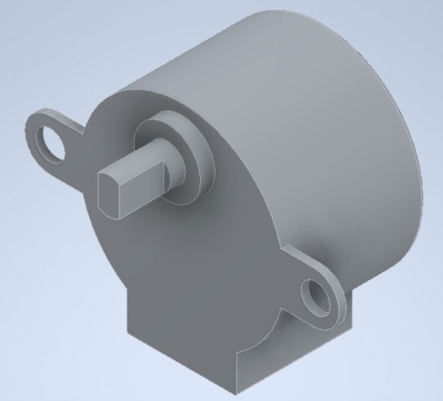
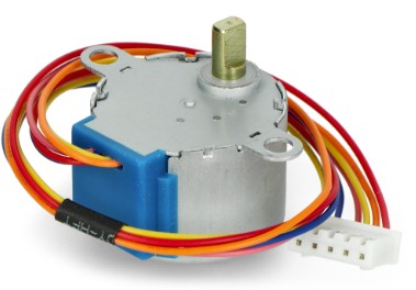
The core mechanism uses a spiral connected to a 28BYJ-48 stepper motor. The spiral is mounted on the motor shaft through a 3D-printed coupling, and when rotated, it advances sanitary pads downward toward the dispensing outlet.
Electronic Architecture
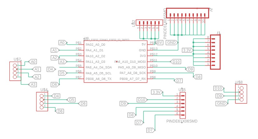
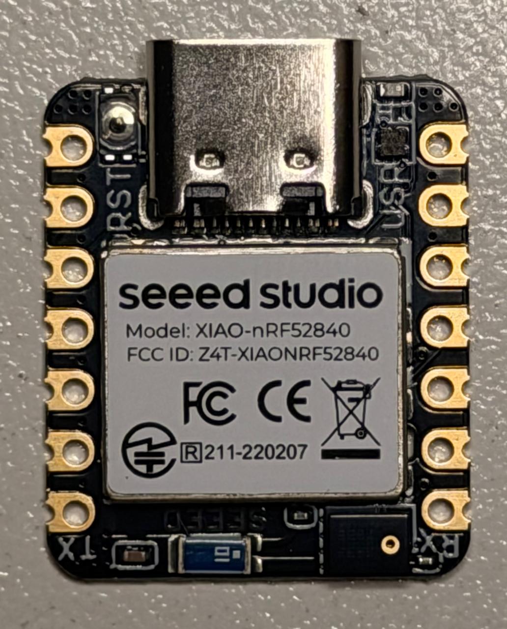
HigiBox electronics are built around a custom PCB and the XIAO ESP32-C3 microcontroller. This combination provides Wi-Fi connectivity, analog input/output, and sufficient processing power for sensor integration, motor control, and TFT display management.
XIAO ESP32-C3 — All-in-one processor with Wi-Fi, GPIO pins, I2C, and SPI
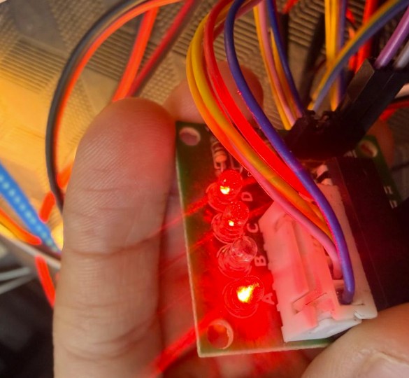
ULN2003 — Controls stepper coils, manages motor rotation logic
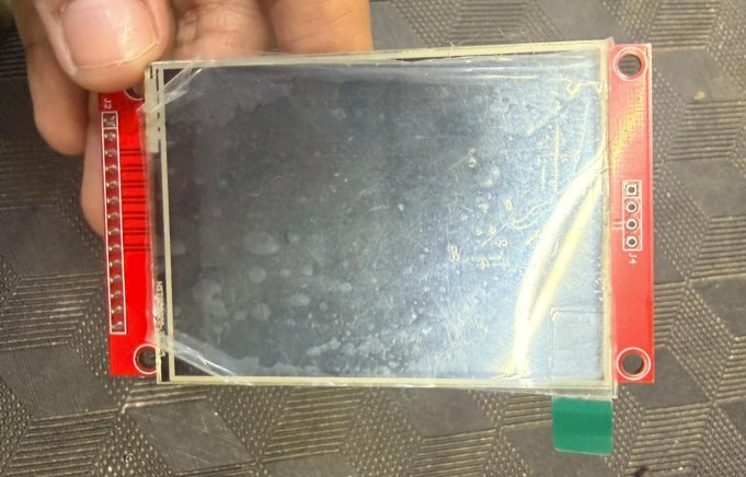
2.8" TFT (ILI9341) — SPI communication, real-time information display
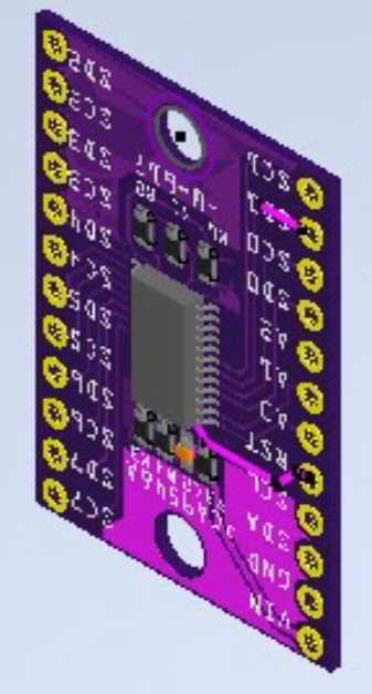
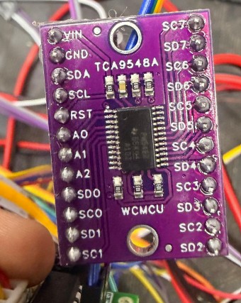
TCA9548A I2C multiplexer routes two VL53L0X sensors to microcontroller
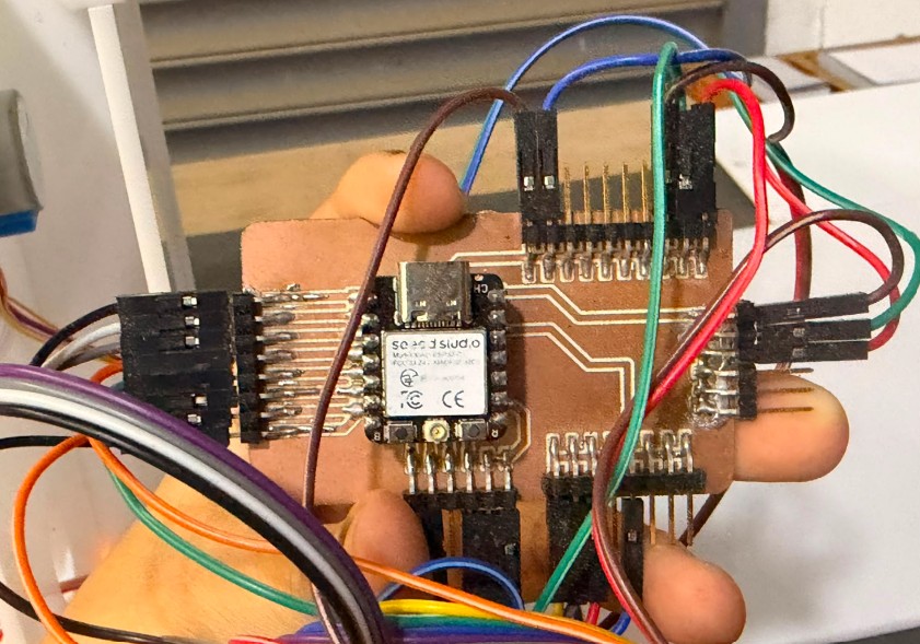
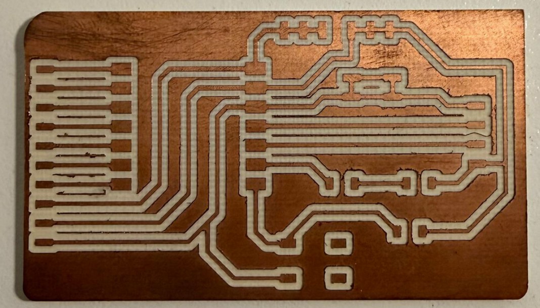
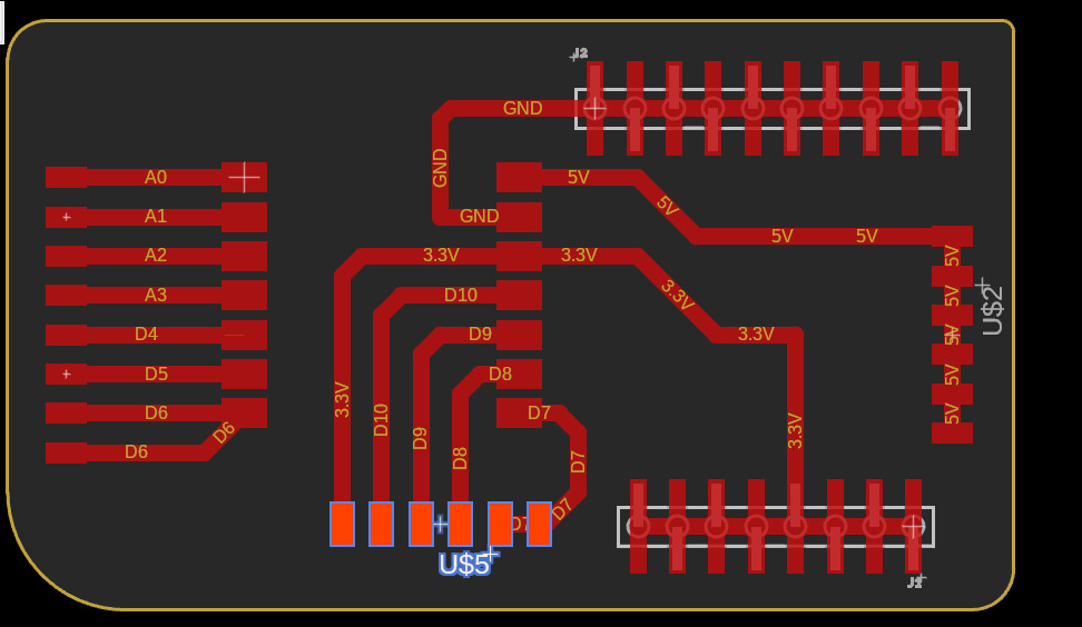
The custom PCB was designed in two iterations. The first prototype failed mechanically, so a second version was optimized for space and signal integrity:
- Thicker traces (30–32 mil) for better current handling
- 45° angled traces instead of 90° angles to reduce signal reflection
- Duplicate power/ground pins for future expansion
- Optimized layout to fit inside HigiBox lower compartment
Power management is critical for an untethered device. The system uses:
- 12 V Rechargeable Battery: Provides primary power, USB Type-C charging
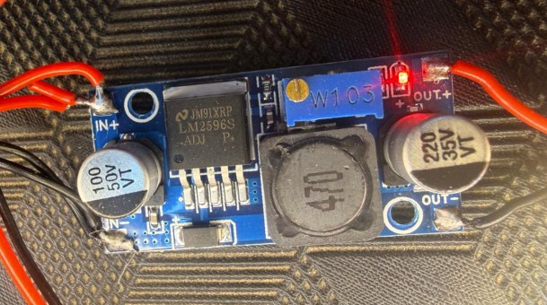
- LM2596 Step-Down: Converts 12 V → 5 V for microcontroller and sensors
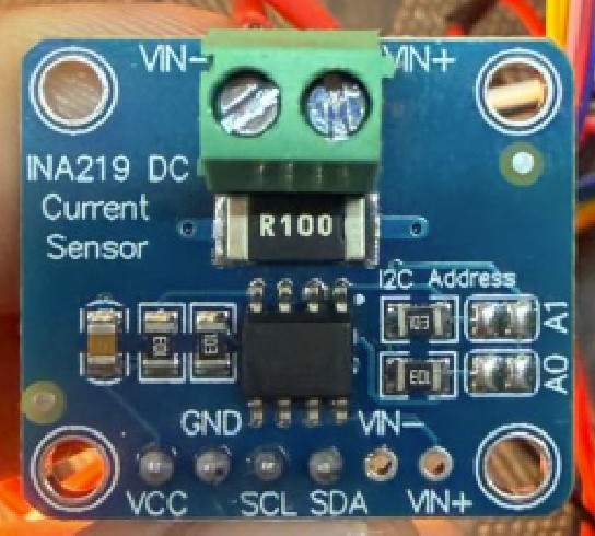
- INA219 Sensor: Real-time voltage/current monitoring, battery percentage estimation
- Battery Display: TFT shows remaining charge, charging alerts
Sensing System
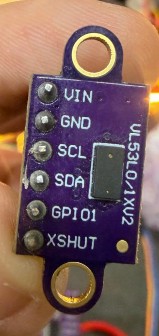
Two VL53L0X Time-of-Flight sensors handle different sensing tasks:
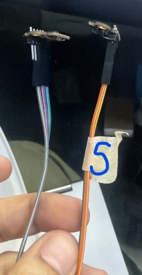
Stock Sensor (Channel 0): Monitors the central spiral area. When distance is short, pads are present. When distance is long, compartment is nearly empty.
Hand-Detection Sensor (Channel 1): Positioned near the dispensing outlet. Activates motor when user places hand within ~150 mm range.
I2C Multiplexer: Both sensors use the same default I2C address, so a TCA9548A multiplexer routes each sensor to a separate channel on the microcontroller.
Fabrication Process
Laser Cutting: Acrylic Enclosure
After refining the digital model, I fabricated the main body of the dispenser using laser-cut acrylic sheets. For this structure, I used 4 mm thick acrylic, which gave the prototype enough rigidity while still being easy to cut and assemble.
I chose acrylic because it allowed me to create a clean and solid structure. It also made it easier to observe the internal mechanism during the testing stage.
Laser Cutting Parameters
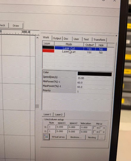
Before cutting the pieces, I prepared the design files and configured the laser cutting parameters carefully:
| Mode | Laser Cut (with output enabled) |
| Cutting Speed | 15 mm/s |
| Power (Minimum) | 60% |
| Power (Maximum) | 60% |
| Priority | 1 |
| Material | 4 mm White Acrylic |
These settings produced clean edges without charring and allowed precise cuts that fit together perfectly during assembly.
Assembly & Testing
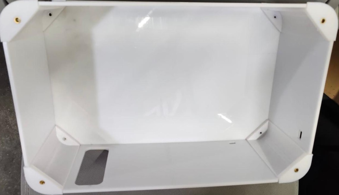
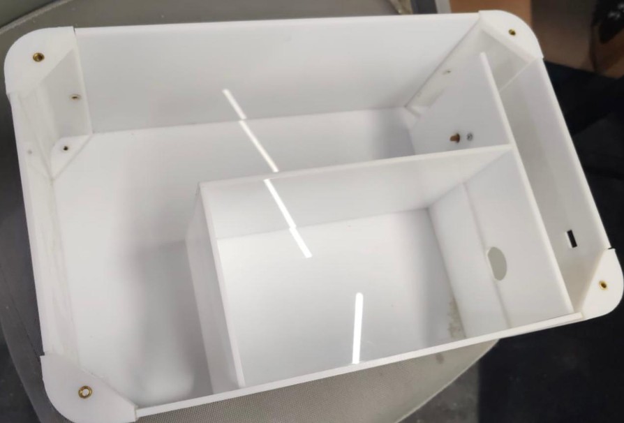
Once the pieces were cut, I assembled the main acrylic body of the dispenser. The walls, base, and internal divisions were joined using chemical glue (cyanoacrylate-based adhesive). This step allowed me to move from the digital model to a real prototype and evaluate if the dimensions and internal spaces worked correctly.
3D Printing: Mechanical Components
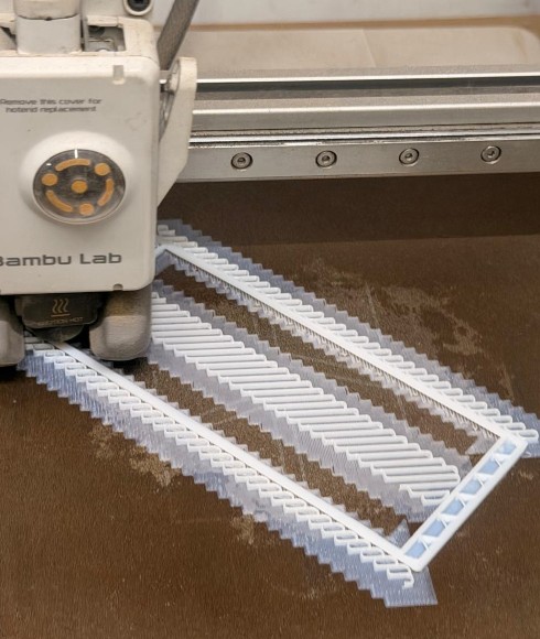
In addition to the laser-cut acrylic structure, I used 3D printing to fabricate the parts that required more complex shapes or mechanical functions. These printed parts were essential for assembling the dispenser, reinforcing the acrylic structure, and making the dispensing mechanism work correctly.
3D-Printed Components
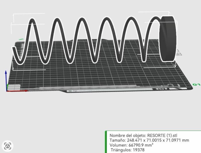
Most important component. This spring pushes the sanitary pads forward inside the dispenser. Before printing, I checked its dimensions in the slicing software to make sure it would fit inside the internal channel and rotate without interfering with the acrylic walls.
This piece connects the motor shaft with the spring mechanism, allowing the motor rotation to be transferred to the dispensing system. Critical for power transmission.
Since the main structure was made with 4 mm acrylic sheets, these printed corners helped connect the acrylic panels more securely. Most corners use 3D-printed press-fit pieces that align walls, reinforce structure, and create a cleaner rounded finish.
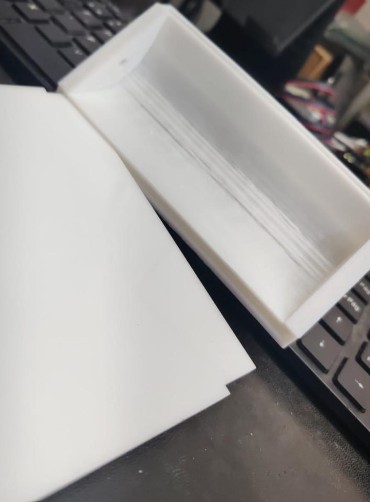
Side wings added after physical testing prevent pads from deviating during dispensing. Ensures consistent and reliable product delivery.
Materials Used: Primarily PolyLite White PLA for structural components and PolyLite Black ABS for high-stress areas requiring more rigidity.
Testing & Iteration
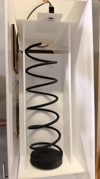
After assembling the printed parts with the acrylic structure, I tested the spring mechanism with real sanitary pads. This test helped me understand how the pads moved inside the dispenser and confirmed that the system needed a more controlled guide.
The first assembly test showed how the acrylic structure, 3D-printed spring, motor coupling, curved corners, and internal guide system worked together. It also helped me improve the final design based on the real behavior of the prototype.
PCB Milling
The custom circuit board was milled from copper-clad substrate using a PCB router. This allowed precise trace routing and component placement optimized for the final enclosure space.
Cable Management & Electronics Integration
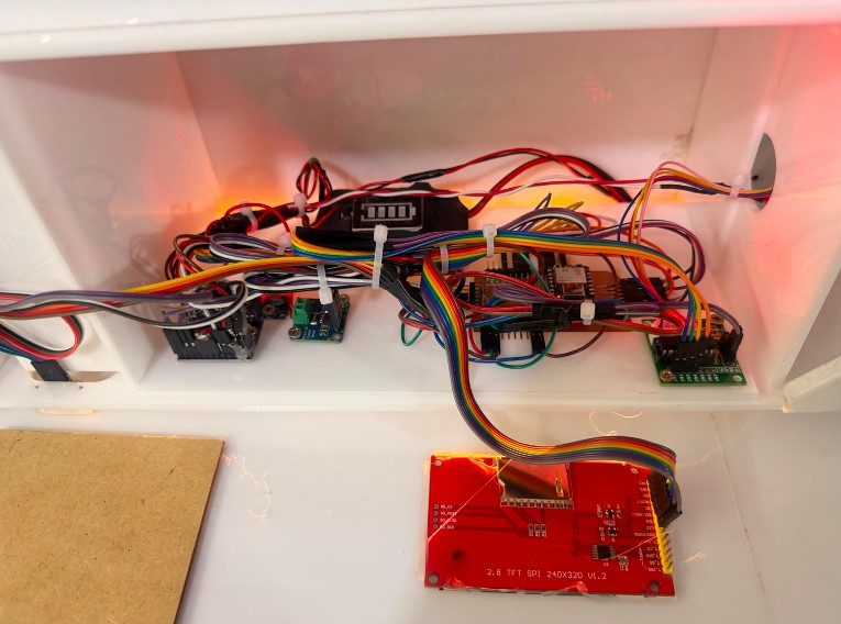
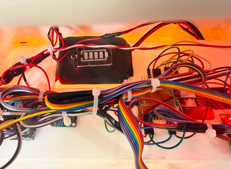
Proper cable organization and sensor mounting was critical for a clean, functional integration. All electronics are mounted on a custom-cut acrylic base that fits precisely inside the lower compartment.
Cable Organization: All interconnecting cables between modules (PCB, motor driver, sensors, battery, display) are bundled using white cable ties and color-coded for easy identification during maintenance and troubleshooting.
Sensor Mounting: The two VL53L0X distance sensors are mounted on threaded standoffs screwed to a dedicated acrylic mounting plate. This plate is the same size as the electronics compartment, allowing precise positioning of sensors in their functional locations without mechanical stress on the delicate sensor modules.
Component Placement: The acrylic base is laser-cut with custom slots and openings to:
- Mount the 12 V battery securely with a recessed pocket
- Hold the custom PCB in a fixed orientation
- Position the INA219 power monitor and LM2596 step-down converter
- Route cables through designated channels to avoid tangling and interference
- Provide ventilation around components that generate heat
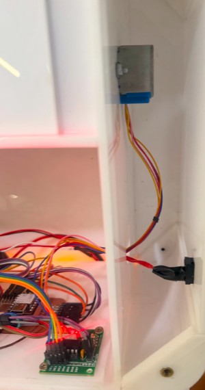
Design for Maintainability: The modular acrylic base allows the entire electronics assembly to be removed as a single unit for debugging, sensor recalibration, or battery replacement. This approach significantly reduces assembly/disassembly time and risk of disconnection.
Assembly & Integration
Final assembly combined all fabrication methods:
- Acrylic structure serves as the main housing
- 3D-printed components reinforce acrylic joints and add mechanical functions
- PCB, motor, sensors, and battery are mounted inside the lower compartment
- Internal wiring connects all modules
- Removable access panels allow refilling and maintenance
Structure Assembly
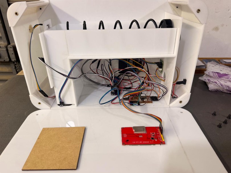
The acrylic structure of the dispenser is complete. The external enclosure is joined with pressure-fit connections and 3D-printed rounded corner pieces. These corners were originally designed to avoid sharp acrylic edges, but they also helped increase the internal space available for wiring and electronics.
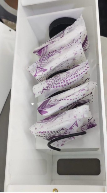
The upper access area allows the user to refill the sanitary pads. Removable access panels using screws enable product refilling and maintenance without full disassembly.
Dispensing Mechanism
The main dispensing mechanism is based on a spiral connected to a motor. The spiral and motor coupling were tested with real sanitary pads to verify movement and spacing.
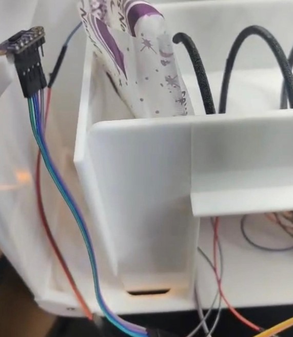
Testing revealed that sanitary pads can sometimes get stuck because they're soft and flexible. The internal guides were added to control pad movement smoothly.
Testing & Evaluation
What Worked Well
4 mm acrylic provided rigidity without excessive weight. 3D-printed corners effectively reinforced joints and enabled modular assembly.
XIAO ESP32-C3 successfully coordinated all modules: sensors, motor, display, battery monitoring, and Wi-Fi.
Proximity sensor worked reliably, activating the motor when hand approached. Improved hygiene and ease of use.
Interface successfully displayed cycle info, battery status, stock level, and motivational messages with clear readability.
Mechanical Challenges
The dispensing mechanism revealed unexpected real-world behavior:
- Product Friction: Sanitary pads are soft and flexible. Packaging materials create friction against acrylic walls and the spiral, sometimes causing pads to get stuck.
- Stock Sensing Accuracy: The distance sensor detects objects, not specific products. Any object in the compartment registers as "available stock," which isn't ideal for inventory reliability.
- Motor Logic: Current design spins motor continuously while hand is detected. Ideal behavior would release exactly one pad per gesture.
Testing Methodology
The prototype was evaluated through physical testing with real sanitary pads:
- ✓ Pads fit correctly in storage area
- ✓ Spiral rotates inside structure without interference
- ✓ Motor successfully rotates spiral
- ✓ Proximity sensor activates system
- ✓ Stock sensor responds to pad presence
- ✓ TFT displays correct information
- ✓ Battery charges via USB Type-C
- ✓ Structure can be opened for refill/maintenance
HigiBox components sourced from local and online electronics suppliers. All costs calculated with exchange rate 1 USD ≈ S/3.50.
| Image | Component | Description | Source | Cost (USD) |
|---|---|---|---|---|
|
2.8" TFT LCD Display | ILI9341 driver, SPI interface, displays system info | Zacatrex Electrónica | $28.57 |
|
VL53L0X Sensors (×2) | Time-of-Flight distance sensors for stock + hand detection | Zacatrex Electrónica | $6.86 |
|
TCA9548A I2C Multiplexer | Routes two identical I2C sensors to microcontroller | Zacatrex Electrónica | $2.29 |
|
INA219 Power Sensor | Measures voltage, current, power consumption | Zacatrex Electrónica | $5.71 |
| Image | Component | Description | Source | Cost (USD) |
|---|---|---|---|---|
|
XIAO ESP32-C3 | Main processor, Wi-Fi, GPIO, I2C, SPI | MTLab UNI | $14.29 |
|
ULN2003 Motor Driver | Controls stepper motor coil activation | Zacatrex Electrónica | $1.43 |
|
28BYJ-48 Stepper Motor | Drives spiral mechanism, ~5–10 RPM output | Fab Lab ULima | $2.86 |
|
LM2596 Step-Down Converter | Converts 12 V battery → 5 V for microcontroller | Zacatrex Electrónica | $2.00 |
|
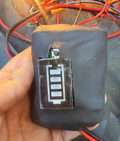
12 V Rechargeable Battery | Li-ion or similar, includes USB Type-C charging | Zacatrex Electrónica | $20.00 |
|
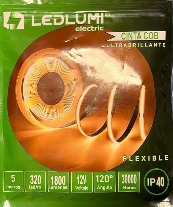
Warm White LED Strip, 5 m | 12 V, adds ambient lighting (optional upgrade) | Local electronics | $5.71 |
| Image | Component | Description | Source | Cost (USD) |
|---|---|---|---|---|
|
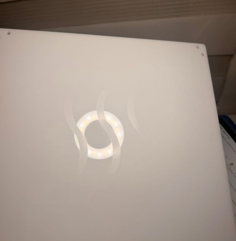
White Acrylic Sheet, 4 mm | Enclosure panels, internal divisions | Fab Lab ULima | $30.00 |
|
PolyLite White PLA | 3D printing: supports, mechanical parts | Fab Lab ULima | $20.00 |
|
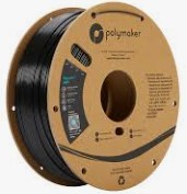
PolyLite Black ABS | 3D printing: high-strength components | Fab Lab ULima | $18.57 |
|
|
Copper-Clad PCB | Raw material for custom board milling | Fab Lab ULima | $1.14 |
|
|
SMD Pins & PCB Connectors | Header pins, screw terminals | Fab Lab ULima | $1.14 |
|
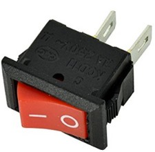
Power Switch & Miscellaneous | On/off switch, screws, adhesives, jumpers | Fab Lab ULima | $0.57 |
|
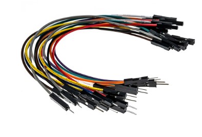
Jumper Cables | Prototyping and integration tests | Fab Lab ULima | $1.43 |
This excludes labor, machine time, electricity, software, prototyping iterations, and equipment depreciation.
The cost breakdown shows that the most expensive elements are the acrylic sheet ($30), 3D printing materials ($38.57), battery system ($20), and display ($28.57). The electronics and sensors are relatively affordable when sourced from local suppliers.
Key Insight: Digital fabrication labs make it possible to create sophisticated devices at reasonable cost. Without access to a Fab Lab, the total would be significantly higher due to outsourcing fabrication services.
Project Summary
Learning Outcomes Achieved
Designed complex geometry in Inventor & Fusion 360, optimized for fabrication and real-world assembly.
Created precision acrylic enclosure with optimized parameters for clean edges and tight tolerances.
Fabricated complex mechanical parts (spiral, coupling, corners) in PLA and ABS with proper support planning.
Custom circuit board optimized for component placement and signal integrity using desktop PCB router.
Coordinated microcontroller, sensors, motor driver, display, and power system into unified circuit.
Arduino/C++ control system handling real-time sensor I/O, Wi-Fi, display management, and motor control.
Combined mechanical, electrical, and software systems to create a functional, user-facing product.
Designed for accessibility, privacy, and support—addressing real-world menstrual health equity.
Real-World Impact
HigiBox demonstrates that Fab Academy skills address genuine human needs. By combining digital design, fabrication, and embedded systems, it's possible to create meaningful solutions to health equity challenges that don't yet exist in commercial markets.
This prototype is proof of concept that personal FemTech devices can be designed, prototyped, and manufactured locally—making menstrual product access more equitable, less stigmatized, and more empowering.
Embedded System Programming & Control Workflow
Note: Development of the embedded control system was supported by Google Gemini AI assistance, which helped with code structure optimization, debugging strategies, and integration of multiple sensor modules.
I developed the control program in the Arduino IDE using a XIAO ESP32-C3 as the main microcontroller. The code integrates the TFT display, two VL53L0X distance sensors, a TCA9548A I2C multiplexer, an INA219 power sensor, Wi-Fi time synchronization, and a 28BYJ-48 stepper motor controlled through a ULN2003 driver.
The program was divided into different sections so each component could be understood, tested, and integrated progressively. This made it easier to debug the system because the display, sensors, battery monitoring, Wi-Fi time, and motor behavior could be analyzed separately before working as one complete dispenser.
Code Overview
In the previous version of the code, the motor made one full revolution when the hand was detected. In this updated version, the motor rotates continuously while the hand remains detected. A safety limit was also added to prevent the motor from spinning forever if the sensor keeps detecting an object.
System Initialization on Power-Up
When the dispenser is powered on, the program performs the following sequence:
1. Initializes the serial monitor
2. Configures the motor pins
3. Turns off motor outputs at startup
4. Sets motor speed
5. Starts SPI communication for TFT display
6. Initializes TFT display and shows loading message
7. Starts I2C communication (SDA/SCL pins)
8. Connects ESP32-C3 to Wi-Fi
9. Synchronizes date/time using NTP server
10. Initializes stock VL53L0X sensor (TCA9548A)
11. Initializes hand-detection sensor (TCA9548A)
12. Turns off all TCA9548A channels
13. Initializes INA219 voltage/current sensor
14. Calculates current menstrual-cycle day
15. Performs first battery and sensor readings
16. Calculates stock percentage
17. Displays first user interface screen
18. Prints "System Ready" to serial monitor
Robustness: If a sensor is not detected, the program stores its status as unavailable and continues operating without using that component. This is useful for debugging because the system does not stop completely if one module fails.
Wi-Fi & NTP Configuration
Wi-Fi is used to obtain the current date and time from an NTP server. Before uploading the code, the Wi-Fi credentials must be replaced with actual values:
const char* WIFI_SSID = "YOUR_WIFI_NAME";
const char* WIFI_PASS = "YOUR_WIFI_PASSWORD";
The time zone is configured for Peru (UTC−5):
const long GMT_OFFSET_SEC = -5 * 3600;
const int DAYLIGHT_OFFSET_SEC = 0;
const char* NTP_SERVER = "pool.ntp.org";
The code first attempts to connect to Wi-Fi and then synchronizes the time through the NTP server. If the time is not synchronized, the program can still read sensors and control the motor, but the date and menstrual-cycle information cannot be updated correctly.
Automatic Resynchronization: The program checks every 60 seconds if Wi-Fi is available and attempts to synchronize the time again:
if (!horaSincronizada && millis() - ultimoIntentoHora >= 60000) {
  ultimoIntentoHora = millis();
  if (WiFi.status() == WL_CONNECTED) {
    sincronizarHora();
  }
}
This makes the system more robust because it can recover if the first time synchronization attempt fails.
VL53L0X Time-of-Flight Sensors with I2C Multiplexing
Two VL53L0X sensors are used in the system. One monitors stock level, the other detects the user's hand. Because both sensors share the same I2C address, they connect through a TCA9548A I2C multiplexer:
#define CANAL_STOCK      0
#define CANAL_DISPENSAR  1

void seleccionarCanalTCA(uint8_t canal) {
  if (canal > 7) return;
  Wire.beginTransmission(TCA_ADDR);
  Wire.write(1 << canal);
  Wire.endTransmission();
}
Stock Estimation: The stock sensor measures distance to estimate available product quantity:
const int STOCK_LLENO_MM = 82;      // Full compartment
const int STOCK_VACIO_MM = 327;     // Empty compartment

stockPorcentaje = map(distanciaStockMM,
                      STOCK_VACIO_MM, STOCK_LLENO_MM,
                      0, 100);
stockPorcentaje = constrain(stockPorcentaje, 0, 100);
Hand Detection Threshold: The dispensing sensor activates when hand is within range:
const int DISTANCIA_DISPENSAR_MM = 150;

if (dispensarDetectado &&
    distanciaDispensarMM > 0 &&
    distanciaDispensarMM < DISTANCIA_DISPENSAR_MM) {
  objetoCercaActual = true;
}
If sensor detection is unreliable, the activation distance can be increased to 180 mm or 220 mm depending on final sensor position.
Stock Sensor in Action
With Stock (Short Distance):
Out of Stock (Long Distance):
28BYJ-48 Stepper Motor Control with ULN2003
The motor configuration and continuous rotation logic:
const int stepsPerRevolution = 2048;
const int VELOCIDAD_RPM = 5;

#define IN1 2
#define IN2 3
#define IN3 4
#define IN4 7

// Correct coil sequence for 28BYJ-48
Stepper myStepper(stepsPerRevolution, IN1, IN3, IN2, IN4);
Continuous Rotation Logic: Motor rotates while hand is detected and stops when hand is removed:
void actualizarMotorContinuo() {
  bool debeGirar = objetoCercaActual && stockPermiteActual;

  if (debeGirar) {
    if (!motorGirando) {
      motorGirando = true;
      tiempoInicioMotor = millis();
      Serial.println("Motor: girando mientras detecta mano");
    }

    // Safety timeout
    if (TIEMPO_MAXIMO_GIRO > 0 &&
        millis() - tiempoInicioMotor >= TIEMPO_MAXIMO_GIRO) {
      motorGirando = false;
      apagarMotor();
      Serial.println("Motor detenido por limite de seguridad");
      return;
    }

    myStepper.step(1);  // One small step at a time
  } else {
    motorGirando = false;
    apagarMotor();
  }
}
Safety Timeout: Motor automatically stops after 5 seconds to prevent indefinite spinning:
const unsigned long TIEMPO_MAXIMO_GIRO = 5000;

void apagarMotor() {
  digitalWrite(IN1, LOW);
  digitalWrite(IN2, LOW);
  digitalWrite(IN3, LOW);
  digitalWrite(IN4, LOW);
}
Continuous Motor Operation in Action
INA219 Power Sensor & Battery Management
The INA219 sensor measures voltage, current, and power consumption. The battery is configured as a 3S lithium-ion pack:
const float BAT_LLENA = 12.6;      // Full charge
const float BAT_BAJA = 10.8;       // Low battery
const float BAT_CRITICA = 9.9;     // Critical level

void leerINA219() {
  shuntMV = ina219.getShuntVoltage_mV();
  busVoltage = ina219.getBusVoltage_V();
  corrienteMA = ina219.getCurrent_mA();
  potenciaMW = ina219.getPower_mW();

  voltajeBateria = busVoltage + (shuntMV / 1000.0);
}
Battery Percentage Calculation:
bateriaPorcentaje = map(
  (int)(voltajeBateria * 100),
  (int)(BAT_CRITICA * 100),
  (int)(BAT_LLENA * 100),
  0, 100);
bateriaPorcentaje = constrain(bateriaPorcentaje, 0, 100);

String estadoBateria() {
  if (!inaDetectado) return "INA219 error";
  if (voltajeBateria <= BAT_CRITICA) return "Bateria critica";
  if (voltajeBateria <= BAT_BAJA) return "Bateria baja";
  return "Bateria OK";
}
A female USB Type-C connector allows charging with standard USB-C chargers, making the device easy to recharge.
Charging Station & USB Type-C Integration
Menstrual Cycle Tracking
The user enters the cycle start date directly in the code:
int cicloInicioYear = 2026;
int cicloInicioMonth = 6;
int cicloInicioDay = 1;

const int CICLO_DIAS = 28;  // Standard cycle length
Cycle Day Calculation:
int calcularDiaCiclo() {
  time_t ahora = time(nullptr);
  struct tm* tm_struct = localtime(&ahora);

  // Calculate days since cycle start
  int diasPasados = // ... calculation

  return (diasPasados % CICLO_DIAS) + 1;
}
Cycle Phase Messages:
String textoFlujo(int dia) {
  if (dia >= 1 && dia <= 2) return "Flujo alto esperado";
  if (dia >= 3 && dia <= 5) return "Flujo moderado";
  if (dia >= 6 && dia <= 7) return "Flujo bajo";
  if (dia >= 12 && dia <= 16) return "Ventana fertil aprox.";
  return "Seguimiento normal";
}
⚠️ Disclaimer: This feature is intended only as a general reference. It should not be considered a medical prediction, diagnosis, or health recommendation.
Future Improvement: A mobile application could allow users to update cycle dates without modifying code manually.
TFT Display with ILI9341
Display configuration and pin assignments:
#define TFT_CS   5
#define TFT_DC   6
#define TFT_RST -1
#define TFT_SCLK 8
#define TFT_MOSI 10

SPI.begin(TFT_SCLK, -1, TFT_MOSI, TFT_CS);
tft.begin();
tft.setRotation(1);
tft.fillScreen(COLOR_BG);
Five Automatic Display Screens:
const unsigned long INTERVALO_PANTALLA = 5000;
const unsigned long INTERVALO_LECTURA = 300;

int pantallaActual = 0;
const int TOTAL_PANTALLAS = 5;

// Screen rotation:
// 1. Menstrual-cycle calendar
// 2. Battery status
// 3. Stock status
// 4. Current cycle day
// 5. Motivational reminder
Screen Updates:
// Sensor readings updated every 300ms
if (millis() - ultimaLecturaMs >= INTERVALO_LECTURA) {
  ultimaLecturaMs = millis();
  // Read all sensors
}

// Display screen changes every 5 seconds
if (millis() - ultimaPantallaMs >= INTERVALO_PANTALLA) {
  ultimaPantallaMs = millis();
  pantallaActual = (pantallaActual + 1) % TOTAL_PANTALLAS;
  mostrarPantallaActual();
}
The interface includes graphical elements such as centered text, progress bars, colored status indicators, a simple calendar, battery information, stock percentage, and motivational messages designed to normalize and celebrate menstrual health.
TFT Display Screens in Action
Test Mode Configuration
During development, a test mode allows the motor to operate even when stock is zero:
const bool PERMITIR_DISPENSAR_SIN_STOCK = true;

stockPermiteActual = PERMITIR_DISPENSAR_SIN_STOCK ||
                     stockPorcentaje > 0;
For Production: Change to false to prevent motor activation when compartment is empty.
Required Arduino Libraries
Install from Arduino Library Manager:
- Adafruit GFX Library — Graphical functions for TFT display
- Adafruit ILI9341 — ILI9341 display driver
- Adafruit VL53L0X — Time-of-Flight distance sensors
- Adafruit INA219 — Power sensor readings
- Adafruit BusIO — Communication support (usually auto-installed)
Included with Arduino/ESP32:
- SPI — TFT display communication
- Wire — I2C sensors and multiplexer
- Stepper — Motor control
- WiFi — Network connectivity
- time — NTP time synchronization
Setup Required: The ESP32 board package must be installed in Arduino IDE to compile and upload to XIAO ESP32-C3.
Implications & Future Directions
The Bigger Picture
HigiBox explores how digital fabrication and embedded systems can address real challenges in menstrual health. The project is not merely about dispensing a product—it's about creating a more accessible, private, and supportive experience.
Current prototype applications:
- Personal Bathrooms: Private, always-available access without restocking concerns
What Could Be Improved
- Better Spiral Design: Smooth geometry with minimal friction to prevent pad sticking
- Improved Internal Guides: More precision to direct pads without material binding
- Sensor Accuracy: Switch to weight-based or microswitch detection instead of distance sensing
- Single-Pad Dispensing: Motor releases exactly one product per hand gesture
- Mobile App: Update menstrual cycle dates without reprogramming; receive refill alerts and notifications
- Blynk Integration: Remote monitoring of battery status, stock level, and usage analytics
- Cloud Logging: Track product usage patterns to optimize inventory
- Emergency Alerts: Notify user when stock runs critically low
- Multi-Product Compartments: Separate storage for day pads, night pads, and panty liners
- Inclusive Design: Customizable interface for different mobility and sensory abilities
- Additional Features: Temperature control for comfort, odor management, or discreet packaging
- Community Integration: Sync with other users' calendars for group events (with consent)
Broader Context: FemTech & Digital Fabrication
This project demonstrates how Fab Academy skills directly address real-world health equity challenges. By combining:
- Digital design (CAD, simulation)
- Additive fabrication (3D printing)
- Subtractive fabrication (laser cutting, PCB milling)
- Electronics design and production
- Embedded programming
- Systems integration
...it's possible to create meaningful devices that don't exist in commercial markets. HigiBox is proof that accessible menstrual care innovation is within reach of student makers, not just large corporations.
HigiBox is open for adaptation and improvement. All files are available for modification under CC BY-NC-SA 4.0 license:
File: week20_finalcode.ino
Complete embedded control program. Remember to modify Wi-Fi credentials and menstrual cycle start date before uploading.
File: week16.higiboxinicio.rar
First 3D model created in Autodesk Inventor during Week 16. This initial prototype helped establish component placement, determine internal space requirements, and verify dimensional constraints. While not the final design, it was essential for understanding spatial relationships and planning the internal architecture.
File: week20.higibox.zip
Complete 3D CAD model in Fusion 360 format. Includes acrylic panels, 3D parts, assemblies of HigiBox, and component references. Modify and improve as needed.
File: finalproject/basecables.dxf
Laser-cutting file for the custom acrylic base that holds all electronics components. Includes recessed pockets for battery, PCB, sensors, and cable routing channels. Ready for 4 mm acrylic.
File: tapasensordis.ipt
Inventor/Fusion 360 carcasa/housing design for the exposed VL53L0X distance sensor. Protects the sensor module while maintaining clear optical path. Includes mounting brackets.
File: week20.placafinal.zip
Complete PCB schematic, layout, and manufacturing files (Gerber format) for milling or ordering. Includes component placement, trace routing optimized for signal integrity, and BOM reference.
File: week16coil.stl
STL file for the spiral spring mechanism used in the first distance sensor testing iteration. Useful as reference for iterating on spiral geometry or for those experimenting with the basic dispensing mechanism.
License: Creative Commons BY-NC-SA 4.0

You are free to use, modify, and redistribute this project as long as you credit the original work, use it non-commercially, and share your improvements under the same license.