What Will It Do?
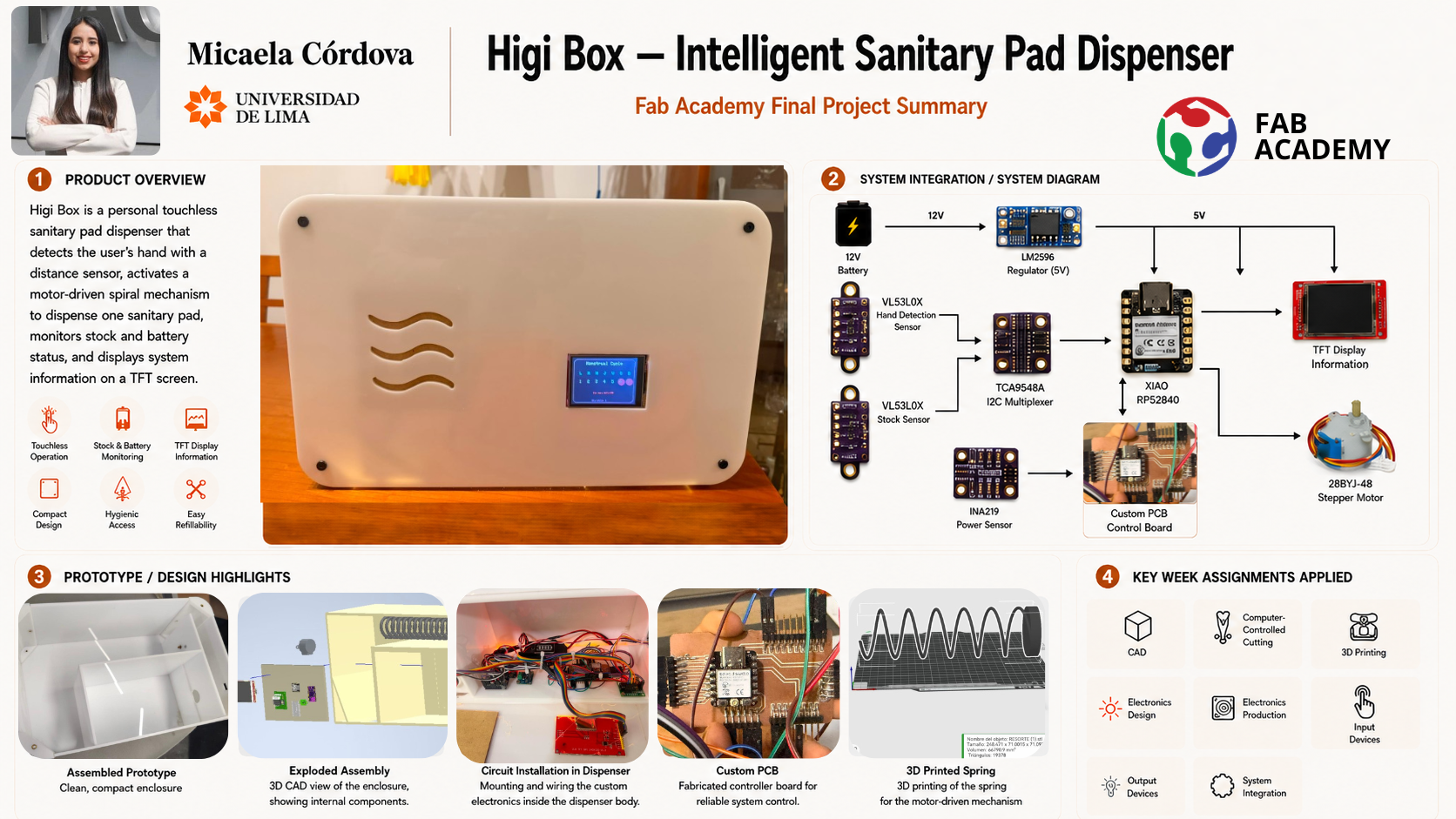
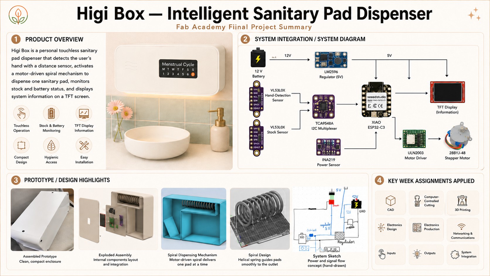
HigiBox is a personal sanitary pad dispenser that combines a motor-driven spiral mechanism, touchless activation, stock monitoring, battery management, and a graphical interface. It stores sanitary pads and automatically dispenses one unit when the user places their hand near the activation sensor.
Core Functionality
The system will:
- Detect the user's hand without physical contact
- Rotate a spiral mechanism to dispense one sanitary pad
- Detect whether sanitary pads are available
- Display stock, battery, cycle, and system information
- Monitor voltage, current, and power consumption
- Obtain current date and time through Wi-Fi
- Operate using a rechargeable 12 V battery
Mechanical Operation
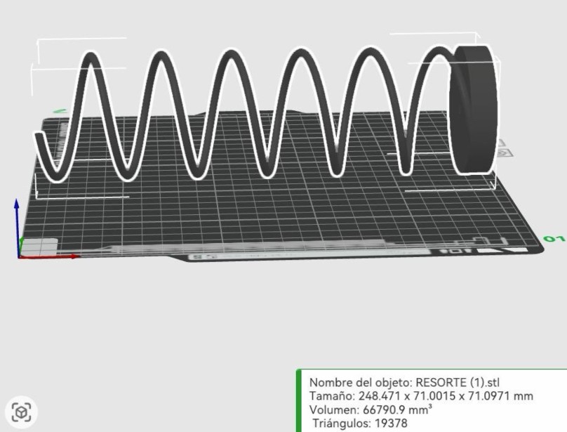
The sanitary pads are positioned between the turns of the spiral. When the stepper motor completes the programmed movement, the spiral advances the products and releases the first sanitary pad through the outlet.
Sensor Configuration
Two VL53L0X sensors enable the system to function autonomously:
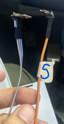
Stock Sensor (S): Marked with a white label, it monitors the central area of the spiral to detect whether sanitary pads are available.
Hand-Detection Sensor: A second sensor detects the user's hand and activates the dispensing sequence when the user approaches the device.
Who's Done What Beforehand?
Commercial Context
Commercial sanitary pad vending machines already exist in universities, schools, workplaces, and public restrooms worldwide. These machines use mechanical systems to store and dispense products efficiently at scale. Studying these machines provided critical insights into vertical storage, spiral movement, product outlets, and motor coupling systems.
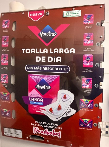
However, commercial dispensers are typically large metal machines intended for public use. They require coins, buttons, or manual activation and do not provide personalized features.
Personal Product Organizers
Most personal-use products found were simple organizers that store sanitary pads vertically or horizontally. These designs require manual removal and refilling, with no integrated sensors, stock monitoring, battery feedback, or digital interface.

The Gap — HigiBox Innovation
HigiBox adapts the operating principle of a commercial vending machine into a smaller device intended for personal use. Its key differentiators are:
No buttons or manual input required—hand detection triggers dispensing automatically.
Real-time awareness of remaining products prevents unexpected empty situations.
Users always know remaining charge and can plan charging ahead of time.
Integrated electronics reduce wiring complexity and improve reliability.
TFT display shows menstrual cycle info, motivational messages, and system status.
Laser-cut acrylic and 3D-printed components ensure precision and customization.
The project was developed using information and inspiration from:
- Commercial sanitary pad vending machines and their spiral mechanisms
- Arduino-based vending machine projects
- Existing personal sanitary pad organizers
- Official datasheets for the XIAO ESP32-C3, VL53L0X, INA219, TCA9548A, ILI9341 display, LM2596, ULN2003, and 28BYJ-48 motor
- Arduino and Adafruit library documentation
- Fab Academy weekly assignments and feedback from instructors
- GrabCAD models used as dimensional references
- Physical measurements of sanitary pads and electronic components
- Individual component and breadboard tests
- Mechanical tests using real sanitary pads
These sources enabled me to compare existing solutions, understand required electronics, estimate available internal space, and identify which parts needed custom design specifically for HigiBox.
What Will I Design?
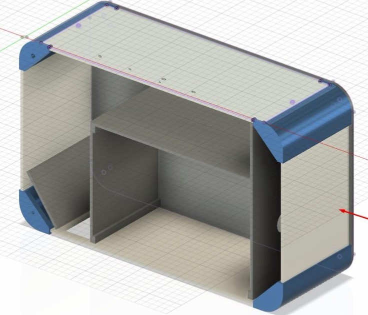
I will design the main mechanical, electronic, structural, and visual elements of HigiBox:
Mechanical Components
- Product-storage compartment
- Rotating dispensing spiral
- Motor-to-spiral coupling
- Motor and spiral support
- Product outlet
- Sensor holders and separators
Structural & Enclosure
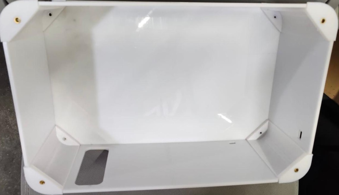
- Acrylic enclosure and internal divisions
- Rounded corner pieces
- Removable panels for access
- Sensor holders and mounting points
- PCB protective case
Electronic Systems
- Custom PCB with power distribution and signal routing
- XIAO ESP32-C3 microcontroller
- Motor driver circuit
- Sensor interface (VL53L0X × 2, INA219 power monitoring)
- Internal cable layout and routing
Software & Interface
- Embedded control program (Arduino/C++)
- Sensor-reading and motor-control functions
- Stock and battery calculation algorithms
- TFT display screen sequence management
- Wi-Fi and NTP time synchronization
- Menstrual-cycle day calculation
Integration & Packaging
- Final system integration and assembly
- Access points for charging and maintenance
- User interface refinement
What Processes Will Be Used?
Computer-Aided Design (CAD)
Autodesk Inventor and Fusion 360 will be used to model the enclosure, internal divisions, spiral, motor coupling, component supports, corners, and complete assembly. Movement and spatial tests will help identify collisions, verify clearances, and evaluate how components fit inside the enclosure.
Laser Cutting & Engraving
The 4 mm acrylic panels, internal divisions, covers, display opening, product outlet, and access panels will be manufactured through laser cutting. Laser engraving will add logo and decorative details. Surface contrast techniques (paint filling or backlighting) may improve visibility on white acrylic.
PCB Milling
Custom circuit boards will be manufactured using a PCB router. The traces, pads, holes, and external board outline will be milled from single-sided copper-clad board. Multiple iterations may be needed to optimize trace routing, pin assignments, and power distribution.
3D Printing (FDM)
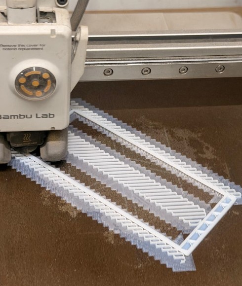
FDM 3D printing will manufacture the dispensing spiral, motor coupling, sensor holders, curved corners, PCB case, and internal supports. The spiral will require careful support structure planning due to its helical geometry.
Mechanical Assembly & Testing
Acrylic and printed parts will be assembled using screws, threaded inserts, adhesives, and custom supports. Physical fitting tests will verify dimensional tolerances, panel alignment, corner compatibility, spiral movement, motor positioning, product clearance, and maintenance access.
Materials, Components & Cost
This Bill of Materials includes electronic components, fabrication materials, power system, mechanical materials, and custom PCB resources required to build HigiBox. Materials supplied by Fab Lab ULima are included using estimated replacement costs.
| Item | Description | Source | Cost (USD) |
|---|---|---|---|
| 2.8" TFT LCD Touchscreen | Displays cycle, battery, stock, and system info | Zacatrex Electrónica | $28.57 |
| TCA9548A I2C Multiplexer | Connects two I2C sensors with same address | Zacatrex Electrónica | $2.29 |
| ULN2003 Motor Driver | Controls stepper motor coils | Zacatrex Electrónica | $1.43 |
| 28BYJ-48 Stepper Motor | Rotates dispensing mechanism | Fab Lab ULima | $2.86 |
| LM2596 Step-Down Converter | Reduces 12V battery to 5V | Zacatrex Electrónica | $2.00 |
| INA219 Power Sensor | Measures voltage, current, and power consumption | Zacatrex Electrónica | $5.71 |
| Custom 12V Battery | Powers system, includes USB Type-C charging | Zacatrex Electrónica | $20.00 |
| VL53L0X Sensors (× 2) | Monitor stock and detect user's hand | Zacatrex Electrónica | $6.86 |
| Jumper Cables | Prototyping and integration tests | Fab Lab ULima | $1.43 |
| White Acrylic Sheet, 4mm | Enclosure and internal divisions | Fab Lab ULima | $30.00 |
| PolyLite White PLA | Supports and mechanical parts | Fab Lab ULima | $20.00 |
| PolyLite Black ABS | Stronger printed components | Fab Lab ULima | $18.57 |
| XIAO ESP32-C3 | Controls sensors, display, motor, Wi-Fi, logic | MTLab UNI | $14.29 |
| Copper-Clad PCB | Custom circuit board manufacturing | Fab Lab ULima | $1.14 |
| SMD Pins & PCB Connectors | Connect external modules to custom PCB | Fab Lab ULima | $1.14 |
| Power Switch | Turns complete electronic system on/off | Fab Lab ULima | $0.57 |
This total does not include labor, machine time, electricity, software, failed prototypes, or equipment depreciation.
Having all the components available does not mean the project is complete. Their final positions, supports, connections, and interaction still need to be validated through testing.
Questions That Need Answers
At this stage, the general concept and system architecture are defined, but several integration decisions still need validation before finalizing the prototype.
Internal Wiring
The cables must travel between the PCB, display, sensors, motor driver, battery, and power modules without interfering with the spiral or product outlet. Key decisions:
- How should cables be routed inside the enclosure?
- Where are the optimal fixing points or guides?
- Do actual cable widths fit within planned internal spaces?
Component Placement
Final positions of the PCB, battery, LM2596, INA219, multiplexer, and motor driver must be confirmed. The electrical sketch helps understand connections, but physical placement inside the actual structure requires testing.
Sensor Compatibility
Can the two VL53L0X sensors, INA219, and TCA9548A communicate reliably in the same circuit? Testing will confirm the I2C multiplexer strategy and data integrity across multiple sensors.
Stock Sensor Position
The stock sensor must point through the central area of the spiral. Key questions:
- Should it be positioned beside the motor, opposite the motor, or closer to the storage compartment center?
- How does laser alignment, available space, and motor interference affect placement?
- What are accurate distance readings with and without sanitary pads?
Hand-Detection Sensor Position
The hand-detection sensor must be accessible from the exterior without accidental activation by nearby objects. Testing will determine:
- Optimal angle and position near the product outlet
- Appropriate detection threshold
- Distance range for reliable activation
Motor & Spiral Alignment
The motor shaft, coupling, and spiral must remain aligned during rotation. Testing will validate whether the printed coupling maintains spiral position without excessive movement, bending, or vibration.
Maintenance Access
Electronic modules must be protected but accessible for charging, repairs, wiring adjustments, and component replacement. This requires removable panels and adequate space around the battery, PCB, connectors, and power switch.
Minimum Objective
When the hand-detection sensor is activated, the motor must rotate the dispensing mechanism and release one sanitary pad. The TFT display must show the current status of the dispenser.
Functionality Criteria
The prototype will be considered functional if it can:
- Detect the user's hand
- Activate the motor only once per detection
- Detect whether sanitary pads are available
- Release one product through the spiral mechanism
- Display stock and system information
- Operate using the rechargeable battery
- Maintain stable communication between modules
- Protect the electronics inside the enclosure
- Allow access for charging and maintenance
Additional Improvements
The following functions will be considered additional improvements rather than minimum requirements:
- Menstrual-cycle calendar
- Current cycle-day calculation
- Battery percentage display
- Wi-Fi and NTP time synchronization
- Motivational reminder screens
- Future mobile application connectivity
- Low-stock notifications
- Improved acrylic lighting and visual feedback